Table of Contents
Advertisement
Quick Links
Advertisement
Table of Contents

Related Manuals for Juniper NFX350


Summary of Contents for Juniper NFX350
- Page 1 NFX350 Network Services Platform Hardware Guide Published 2020-03-23...
- Page 2 END USER LICENSE AGREEMENT The Juniper Networks product that is the subject of this technical documentation consists of (or is intended for use with) Juniper Networks software. Use of such software is subject to the terms and conditions of the End User License Agreement (“EULA”) posted at https://support.juniper.net/support/eula/.
-
Page 3: Table Of Contents
NFX350 Device Models | 20 Benefits and Uses of NFX350 | 23 NFX350 Chassis | 24 Front Panel of an NFX350 Device | 24 Rear Panel of an NFX350 Device | 24 LED Details of an NFX350 Device | 25... - Page 4 Chassis Physical Specifications for an NFX350 Device | 44 Environmental Requirements and Specifications for an NFX350 Device | 44 Site Electrical Wiring Guidelines | 45 Clearance Requirements for Airflow and Hardware Maintenance for an NFX350 Device | 46 Rack Requirements for NFX350 Devices | 47...
- Page 5 Management Port Connector Pinout Information for an NFX350 Device | 60 Network Port Connector Pinout Information for an NFX350 Device | 61 RJ-45 to DB-9 Serial Port Adapter Pinout Information for an NFX350 Device | 62 Initial Installation and Configuration...
- Page 6 Mounting an NFX350 Device on Four Posts in a Rack or Cabinet | 67 Connecting the NFX350 to Power | 71 Connecting Earth Ground to an NFX350 Device | 71 Parts and Tools Required for Connecting an NFX350 Device to Earth Ground | 72...
- Page 7 Locating the Serial Number on an NFX350 Device | 118 Listing the Device and Components Details with the CLI | 118 Locating the Chassis Serial Number ID Label on an NFX350 Device | 119 Contacting Customer Support to Obtain a Return Materials Authorization for an NFX350...
- Page 8 Restricted Access Warning | 133 Ramp Warning | 135 Rack-Mounting and Cabinet-Mounting Warnings | 136 Laser and LED Safety Guidelines and Warnings for the NFX350 Devices | 141 General Laser Safety Guidelines | 142 Class 1M Laser Product Warning | 143...
- Page 9 TN Power Warning | 164 Agency Approvals for NFX350 Devices | 164 Compliance Statements for EMC Requirements for NFX350 Devices | 166 Canada | 166 European Community | 167 Israel | 167 Japan | 167 Korea | 168 United States | 168...
-
Page 10: About The Documentation
Use this guide to install hardware and perform initial software configuration, routine maintenance, and troubleshooting for the NFX350 Series devices. After completing the installation and basic configuration procedures covered in this guide, refer to the How to Configure NFX350 guide for information about further software configuration. -
Page 11: Merging A Full Example
If the example configuration contains the top level of the hierarchy (or multiple hierarchies), the example is a full example. In this case, use the load merge command. If the example configuration does not start at the top level of the hierarchy, the example is a snippet. In this case, use the load merge relative command. -
Page 12: Merging A Snippet
Merging a Snippet To merge a snippet, follow these steps: 1. From the HTML or PDF version of the manual, copy a configuration snippet into a text file, save the file with a name, and copy the file to a directory on your routing platform. For example, copy the following snippet to a file and name the file ex-script-snippet.conf. - Page 13 xiii Table 1: Notice Icons Icon Meaning Description Informational note Indicates important features or instructions. Caution Indicates a situation that might result in loss of data or hardware damage. Warning Alerts you to the risk of personal injury or death. Laser warning Alerts you to the risk of personal injury from a laser.
- Page 14 Table 2: Text and Syntax Conventions (continued) Convention Description Examples Italic text like this Represents variables (options for Configure the machine’s domain which you substitute a value) in name: commands or configuration [edit] statements. root@# set system domain-name domain-name Text like this Represents names of configuration To configure a stub area, include statements, commands, files, and...
-
Page 15: Documentation Feedback
URL or page number, and software version (if applicable). Requesting Technical Support Technical product support is available through the Juniper Networks Technical Assistance Center (JTAC). If you are a customer with an active Juniper Care or Partner Support Services support contract, or are... -
Page 16: Self-Help Online Tools And Resources
JTAC hours of operation—The JTAC centers have resources available 24 hours a day, 7 days a week, 365 days a year. Self-Help Online Tools and Resources For quick and easy problem resolution, Juniper Networks has designed an online self-service portal called the Customer Support Center (CSC) that provides you with the following features: Find CSC offerings: https://www.juniper.net/customers/support/... -
Page 17: Overview
C HAPTER Overview NFX350 Network Services Platform Overview | 18 NFX350 Chassis | 24 NFX350 Interface Modules | 30 NFX350 Cooling System | 35 NFX350 Power System | 36... -
Page 18: Nfx350 Network Services Platform Overview
NFX350 enables service providers to deploy and chain multiple, secure, high-performance virtualized network functions (VNFs) on a single device. The NFX350 is suited for large and extra-large deployments. The NFX350 is a high-end resilient uCPE platform that can be used in secure SD-WAN and secure router deployments. -
Page 19: Nfx350 Hardware
NFX350 Hardware The NFX350 portfolio consists of rack-mount models, with LTE support. The NFX350 device has a 1 U form factor and comes with built-in fans and power supply. The NFX350 device can be used as: A SD-WAN solution. A resilient uCPE platform. -
Page 20: Nfx350 Device Models
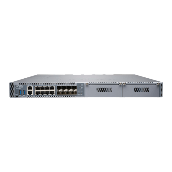
NFX350 Device Models The NFX350 device is available in three models, with LTE support. All models are shipped with built-in AC power supply and have airflow-out (front-to-back) cooling. Table 4 on page 20 lists the NFX350 Series device models with device configurations. - Page 21 Asia, frequency bands in Asia, frequency bands in Asia, Australia, and New Australia, and New Australia, and New Zealand. Zealand. Zealand. Figure 3 on page 22 shows the front panel of the NFX350 device.
- Page 22 Figure 3: NFX350 Device Figure 4 on page 22 shows the rear panel of the NFX350 device. Figure 4: Rear Panel of the NFX350 Device Figure 5 on page 22 shows the NFX-LTE-AA and NFX-LTE-AE devices. NFX-LTE-AA is a device model with integrated LTE modem for Asia, Australia, and New Zealand.
-
Page 23: Benefits And Uses Of Nfx350
Benefits and Uses of NFX350 The NFX350 Network Services Platform provides these benefits: Highly scalable, supporting multiple Juniper and third-party VNFs on a single device. The modular software architecture provides high performance and scalability for routing, switching, and security enhanced by carrier-class reliability. -
Page 24: Nfx350 Chassis
— System status LEDs Mini-USB console port — — Rear Panel of an NFX350 Device Figure 7 on page 25 shows the rear panel of the NFX350 device. The rear panel of the NFX350 device consists of the following components:... -
Page 25: Led Details Of An Nfx350 Device
Management Port LEDs | 27 LTE Module LEDs | 29 Chassis Status LEDs The front panel of an NFX350 device has chassis status LEDs labeled ALM, SYS, MST and PH. Figure 8 on page 26 shows the chassis status LEDs in an NFX350 device. - Page 26 — Table 5 on page 26 describes the chassis status LEDs in an NFX350 device, their colors and states, and the status they indicate. You can view the colors of the four LEDs remotely through the CLI by issuing the operational mode command show chassis led.
-
Page 27: Network Port And Uplink Port Leds
All four LEDs can be lit simultaneously. Network Port and Uplink Port LEDs Each network port and uplink port on the front panel of an NFX350 has two LEDs that indicate link activity and port status (see Figure 9 on page 27). - Page 28 Table 7: Link/Activity LED on the Management Port of an NFX350 Device Color State and Description Link Green solid (On) The link is up. The link is down. Activity Green blinking There is traffic on this port. There is no traffic on this port.
-
Page 29: Lte Module Leds
SIM2 is active NOTE: If all the LEDs are blinking, it indicates that firmware updates are in progress. Do not power off the device before the updates complete. RELATED DOCUMENTATION NFX350 Cooling System | 35 NFX350 Power System | 36... -
Page 30: Nfx350 Interface Modules
Understanding the LTE Logical Interface | 32 Overview The LTE module operates on both 3G and 4G networks and provides wireless WAN support on the NFX350 devices. The NFX350 portfolio consists of models with or without LTE support. provides a summary of the models that support LTE. -
Page 31: Features Supported On The Lte Module For Nfx Devices
Model Mode Operating Region Frequency Band NFX-LTE-AA (expansion module Asia For LTE: supported on the NFX350-S1, HSPA+ Australia Bands 1,3, 5, 7, 8, 18, 19, 21, 28, 38, NFX350-S2, and NFX350-S3) New Zealand 39, 40, and 41 For 3G (HSPA+):... -
Page 32: Understanding The Lte Physical Interface
Primary and backup interface—You can configure the LTE module either as a primary interface or as a backup interface. When configured as the primary interface, the LTE module supports both the Always-on and Dial-on-demand modes. When configured as the backup interface, the LTE module connects to the network only when the primary interface fails. -
Page 33: Lte Expansion Module (Nfx-Lte-Ae And Nfx-Lte-Aa)
You configure the following for a dialer interface: A dialer pool to which the physical interface belongs. Dial string (destination number to be dialed). You can also specify optional operating parameters for the dialer interface: Activation delay—Number of seconds after the primary interface is down before the backup interface is activated. - Page 34 Impedance 50 Ohms Radiation Omnidirectional Gain 1-4 dBi Polarization Vertical Connector type Length 120 mm The antenna is connected to the NFX350 device through the magnetic antenna base. Table 14 on page 35 lists the specifications for the antenna base.
-
Page 35: Nfx350 Cooling System
NFX350 Cooling System The NFX350 devices have front-to-back airflow. The air intake to cool the chassis is located on the front of the chassis. Air is pulled into the chassis and pushed toward the fans. Hot air exhausts from the rear of the chassis. -
Page 36: Nfx350 Power System
AC Power Cord Specifications for an NFX350 Device | 38 Power Supply in NFX350 Devices NFX350 devices use a pluggable power supply. The power supply distributes different output voltages to the device components according to their voltage requirements. The power supply is field-replaceable. - Page 37 Table 16: AC Power Specifications for an NFX350 Device AC Input Voltage Maximum Product (Operating AC Input Line AC Input Power Power Supply SKUs Range) Frequency Current Rating Consumption Type NFX350-S1 100 through 240 50–60 Hz 3.7 A to 1.7 A...
-
Page 38: Ac Power Cord Specifications For An Nfx350 Device
Table 17: DC Power Specifications for an NFX350 Device (continued) DC Input Voltage DC Input Current Maximum Power Product SKUs (Operating Range) Rating Consumption Power Supply Type NFX350-S3 Minimum operating 8.0 A maximum at 230 W External, hot voltage: -40 VDC... - Page 39 Table 18: AC Power Cord Specifications Country/Region Electrical Specifications Plug Standards Juniper Model Number Argentina 250 VAC, 10 A, 50 Hz IRAM 2073 Type RA/3 CBL-EX-PWR-C13-AR Australia 250 VAC, 10 A, 50 Hz AS/NZZS 3112 Type CBL-EX-PWR-C13-AU SAA/3 Brazil 250 VAC, 10 A, 50 Hz...
- Page 40 Figure 12: AC Plug Types SEE ALSO General Safety Guidelines and Warnings | 124 General Electrical Safety Guidelines and Warnings | 159 Prevention of Electrostatic Discharge Damage | 160...
-
Page 41: Site Planning, Preparation, And Specifications
C HAPTER Site Planning, Preparation, and Specifications Site Preparation Checklist for NFX350 Devices | 42 NFX350 Site Guidelines and Requirements | 43 NFX350 Network Cable and Transceiver Planning | 50 NFX350 Cable Specifications and Pinouts | 57... -
Page 42: Site Preparation Checklist For Nfx350 Devices
Locate sites for connection of system grounding. Calculate the power consumption and “AC Power Supply Specifications requirements. for an NFX350 Device” on page 36 Hardware Configuration Choose the number and types of devices “NFX350 Network Services you want to install. -
Page 43: Nfx350 Site Guidelines And Requirements
Environmental Requirements and Specifications for an NFX350 Device | 44 Site Electrical Wiring Guidelines | 45 Clearance Requirements for Airflow and Hardware Maintenance for an NFX350 Device | 46 Rack Requirements for NFX350 Devices | 47 Cabinet Requirements for an NFX350 Device | 49... -
Page 44: General Site Guidelines
Install the device in a secure area, so that only authorized personnel can access the device. Chassis Physical Specifications for an NFX350 Device NFX350 device chassis is a rigid sheet-metal structure that houses the hardware components. Table 20 on page 44 summarizes the physical specifications of the NFX350 chassis. -
Page 45: Site Electrical Wiring Guidelines
Table 21 on page 45 provides the required environmental conditions for normal operation of the device. Table 21: NFX350 Device Environmental Tolerances Description Tolerance Altitude No performance degradation up to 2000 meters at 96°... -
Page 46: Clearance Requirements For Airflow And Hardware Maintenance For An Nfx350 Device
Electrical hazards as a result of power surges conducted over the lines into the equipment Clearance Requirements for Airflow and Hardware Maintenance for an NFX350 Device When planning the site for installing an NFX350 device, you must allow sufficient clearance around the installed chassis (see Figure 13 on page... -
Page 47: Rack Requirements For Nfx350 Devices
Leave at least 24 in. (61 cm) both in front of and behind the NFX350 device. For service personnel to remove and install hardware components, you must leave adequate space at the front and back of the NFX350. - Page 48 Rack type Mounting bracket hole spacing Rack size and strength Rack connection to the building structure Table 23 on page 48 provides the rack requirements and specifications for the device. Table 23: Rack Requirements and Specifications for the Device Rack Requirement Guidelines Rack type Use a four-post rack.
-
Page 49: Cabinet Requirements For An Nfx350 Device
Rack-Mounting and Cabinet-Mounting Warnings | 136 Cabinet Requirements for an NFX350 Device You can mount the NFX350 device in an enclosure or cabinet that contains a four-post 19-in. open rack as defined in Cabinets, Racks, Panels, and Associated Equipment (document number EIA-310-D) published by the Electronics Industry Association. -
Page 50: Nfx350 Network Cable And Transceiver Planning
If the cabinet contains a top or doors, perforations in these elements assist with removing the hot air exhaust. Install the NFX350 device in the cabinet in a way that maximizes the open space on the side of the chassis that has the hot air exhaust. -
Page 51: Sfp+ Direct Attach Cables For Nfx350 Devices
Juniper Networks with your Juniper Networks device. CAUTION: If you face a problem running a Juniper Networks device that uses a third-party optic or cable, the Juniper Networks Technical Assistance Center (JTAC) can help you diagnose the source of the problem. Your JTAC engineer might recommend that you check the third-party optic or cable and potentially replace it with an equivalent Juniper Networks optic or cable that is qualified for the device. -
Page 52: Cable Specifications
Cable Specifications NFX350 devices support SFP+ passive DAC cables. The passive Twinax cable is a straight cable with no active electronic components. NFX350 devices support 1 m, 3 m, and 5 m long SFP+ passive DAC cables. NOTE: We recommend that you use only SFP+ DAC cables purchased from Juniper Networks with your Juniper Networks device. -
Page 53: Understanding Nfx350 Devices Fiber-Optic Cable Signal Loss, Attenuation, And Dispersion
It is consequently more expensive. For information about the maximum transmission distance and supported wavelength range for the types of single-mode and multimode fiber-optic cables that are connected to the NFX350 devices, see “Pluggable Transceivers Supported on NFX350 Devices”... -
Page 54: Calculating The Fiber-Optic Cable Power Budget For An Nfx350 Device
The optical power budget must allow for the sum of component attenuation, power penalties (including those from dispersion), and a safety margin for unexpected losses. Calculating the Fiber-Optic Cable Power Budget for an NFX350 Device Calculate the link's power budget when planning fiber-optic cable layout and distances to ensure that fiber-optic connections have sufficient power for correct operation. -
Page 55: Calculating The Fiber-Optic Cable Power Margin For An Nfx350 Device
) from (PT): –15 dBm – (–28 dBm) = 13 dBm Calculating the Fiber-Optic Cable Power Margin for an NFX350 Device Calculate the link's power margin when planning fiber-optic cable layout and distances to ensure that fiber-optic connections have sufficient signal power to overcome system losses and still satisfy the minimum input requirements of the receiver for the required performance level. - Page 56 Table 25: Estimated Values for Factors Causing Link Loss (continued) Link-Loss Factor Estimated Link-Loss Value Sample Link Loss (LL) Calculation Values Modal and chromatic Multimode—None, if product of 0 dBm dispersion bandwidth and distance is less than 500 MHz/km Single-mode—None 0 dBm Connector 0.5 dBm...
-
Page 57: Nfx350 Cable Specifications And Pinouts
Management Port Connector Pinout Information for an NFX350 Device | 60 Network Port Connector Pinout Information for an NFX350 Device | 61 RJ-45 to DB-9 Serial Port Adapter Pinout Information for an NFX350 Device | 62 Cable Specifications for Console and Management Connections for the... -
Page 58: Mini-Usb Type-B Console Port Specifications For An Nfx350 Device
Mini-USB Type-B Console Port Specifications for an NFX350 Device NFX350 Device has two: an RJ-45 port, and a Mini-USB port. By default, the RJ-45 port is set as the active console port. It can display all the early boot and low-level message output and you can access the device through this port in the debugger prompt. -
Page 59: Usb Port Specifications For An Nfx350 Device
If your laptop or PC does not have a DB-9 male connector pin and you want to connect your laptop or PC directly to an NFX350 device, use a combination of the RJ-45 cable and RJ-45 to DB-9 adapter supplied with the device and a USB to DB-9 male adapter. You must provide the USB to DB-9 male adapter. -
Page 60: Management Port Connector Pinout Information For An Nfx350 Device
NFX350 Chassis | 24 Management Port Connector Pinout Information for an NFX350 Device The 1000BASE-T RJ-45 management port on an NFX350 device uses an RJ-45 connector to connect to a management device for out-of-band management. Table 29 on page 60 provides the pinout information of the RJ-45 management port connector. -
Page 61: Network Port Connector Pinout Information For An Nfx350 Device
NFX350 Chassis | 24 Network Port Connector Pinout Information for an NFX350 Device A network port on an NFX350 device uses an RJ-45 connector to connect to a device. The port uses an autosensing RJ-45 connector to support a 10/100/1000Base-T connection. Two LEDs on the port indicate link/activity on the port and the port status. -
Page 62: Rj-45 To Db-9 Serial Port Adapter Pinout Information For An Nfx350 Device
PC or a laptop. If your laptop or PC does not have a DB-9 male connector pin and you want to connect your laptop or PC to an NFX350 device, use a combination of the RJ-45 to DB-9 female adapter supplied with the switch along with a USB to DB-9 male adapter. -
Page 63: Initial Installation And Configuration
NFX350 Installation Overview | 64 Unpacking and Mounting the NFX350 | 64 Connecting the NFX350 to Power | 71 Connecting the NFX350 to the Network | 80 Initial Configuration on NFX350 Devices | 83 Installing and Configuring the NFX350 Expansion Modules | 86... -
Page 64: Nfx350 Installation Overview
1. Follow instructions in “Unpacking and Mounting the NFX350” on page 2. Mount the device by following instructions appropriate for your site: “Mounting an NFX350 Device on Four Posts in a Rack or Cabinet” on page 67 (using the four-post rack-mount kit). -
Page 65: Unpacking An Nfx350 Device
Unpacking an NFX350 Device The NFX350 devices are shipped in a cardboard carton, secured with foam packing material. The carton has an accessory compartment and contains the quick start instructions. CAUTION: NFX350 devices are maximally protected inside the shipping carton. Do not unpack the devices until you are ready to begin installation. -
Page 66: Registering Products-Mandatory For Validating Slas
SEE ALSO NFX350 Network Services Platform Overview | 18 Registering Products—Mandatory for Validating SLAs Register all new Juniper Networks hardware products and changes to an existing installed product using the Juniper Networks website to activate your hardware replacement service-level agreements (SLAs). -
Page 67: Mounting An Nfx350 Device
Mounting an NFX350 Device on Four Posts in a Rack or Cabinet You can mount an NFX350 device on four posts of a 19-in. rack or cabinet by using the four-post rack-mount kit. (The remainder of this topic uses rack to mean rack or cabinet.). - Page 68 Guidelines for NFX350 Devices” on page 131. Remove the device from the shipping carton (see “Unpacking and Mounting the NFX350” on page 64). Have two persons available to mount the device. One person will support the device in a level position, and the second person will secure the device to the rack.
- Page 69 Figure 14: Attaching the Front-Mounting Bracket to the Side Mounting-Rail 3. Align a front bracket (either flush with the front of the chassis or 2-in.-recessed from the front of the chassis) along the side panel of the device chassis. Align the two holes in the front of the brackets with the two holes on the front of the side panel.
- Page 70 the front-mounting brackets with a hole in each rack rail, making sure the chassis is level. See Figure 16 on page 70 Figure 17 on page Figure 16: Attaching the Device to the Rack Figure 17: Mounting the Device on the Front Posts in a Rack 8.
-
Page 71: Connecting The Nfx350 To Power
Connecting DC Power to an NFX350 Device | 75 Connecting Earth Ground to an NFX350 Device IN THIS SECTION Parts and Tools Required for Connecting an NFX350 Device to Earth Ground | 72 Connecting Earth Ground to an NFX350 Device | 72... -
Page 72: Parts And Tools Required For Connecting An Nfx350 Device To Earth Ground
Electromagnetic Compatibility (EMC) and Electrostatic Discharge (ESD) requirements are met by the device. The AC power cord provides surge protection. To connect NFX350 device to earth ground, you must use the protective earthing terminal on the device. This topic describes:... -
Page 73: Connecting Ac Power To An Nfx350 Device
Ensure that the cable does not drape where people could trip over it. Connecting AC Power to an NFX350 Device The power supply in an NFX350 device is located on the rear panel. Ensure that you have the following parts and tools available:... - Page 74 Figure 20: Front Panel Components of the NFX350 AC Power Supply Input status LED AC power cord retainer installed — — Output status LED Ejector level — — Fault LED — Figure 21: NFX350 AC Power Supply To connect AC power to the device: 1.
-
Page 75: Connecting Dc Power To An Nfx350 Device
The retainer brackets on your device might be above and below the power inlet rather than on either side. Figure 22: Connecting an AC Power Cord to the AC Power Cord Inlet on NFX350 Device Connecting DC Power to an NFX350 Device... - Page 76 DC power source cables (14 AWG) with ring lug (Molex 0190700067 or equivalent) (not provided) attached to them by a licensed electrician Phillips (+) screwdriver, number 2 Figure 23 on page 77 Figure 24 on page 77 show the AC power supply unit for the NFX350 device.
- Page 77 Figure 23: Front Panel Components of the NFX350 DC Power Supply Handle Output LED — — Ejector level Input LED — — Fault LED — Figure 24: NFX350 DC Power Supply...
- Page 78 4. Connect the power supply to the power sources. Secure power source cables to the power supply by screwing the ring lugs attached to the cables to the appropriate terminals by using the screw from the terminals. Figure 25: Connecting a DC Power Cord to the DC Power Cord Inlet on NFX350 Device...
- Page 79 To connect the power supply to a power source: a. Secure the ring lug of the positive (+) DC power source cable to the A+ or B+ terminal on the DC power supply. b. Secure the ring lug of the negative (–) DC power source cable to the A– or B– terminal on the DC power supply.
-
Page 80: Connecting The Nfx350 To The Network
1-Gigabit Ethernet RJ-45 ports, two 1-Gigabit Ethernet RJ-45 network/uplink ports, two 1-Gigabit Ethernet small form-factor pluggable (SFP) ports, and two 1/10-Gigabit Ethernet SFP+ ports. Use the management port to connect the NFX350 device to a network for out-of-band management. -
Page 81: Connecting An Nfx350 Device To A Management Console
NFX350 Chassis | 24 Connecting an NFX350 Device to a Management Console NFX350 device has a console port with an RJ-45 connector. Use the console port to connect the device to a management console or to a console server. Ensure that you have an RJ-45 to DB-9 rollover cable available. An RJ-45 cable with an RJ-45 to DB-9 adapter is provided with the device. -
Page 82: Connecting An Nfx350 Device To A Management Console Using Mini-Usb Type-B Console Port
If your laptop or PC does not have a DB-9 male connector pin or RJ-45 connector pin, you can connect your laptop or PC directly to an NFX350 device by using a mini-USB cable that has a Standard-A USB connector on one end and a Mini-USB Type-B (5 pin) connector on the other end. -
Page 83: Initial Configuration On Nfx350 Devices
1 mini-USB cable with Standard-A and Mini-USB Type- B (5-pin) connectors (not provided). To connect the NFX350 device to the console using Mini-USB Type-B console port: 1. Connect the Standard-A connector of the mini-USB cable to the host machine (PC or Laptop). -
Page 84: Enabling Basic Connectivity
Table 35: Security Policies (continued) Source Zone Destination Zone Policy Action trust untrust permit Table 36: Interfaces Port Label Interface Security Zone DHCP State IP Address 0/0 to 0/7 ge-0/0/0 to ge-0/0/7 trust server 192.168.2.1/24 0/8 to 0/15 xe-0/0/8 to trust client ISP assigned... - Page 85 To use the mini-USB console port, you must download the USB driver from the following page and install the driver on the management device: https://www.juniper.net/support/downloads/junos.html 3. Use any terminal emulation program such as HyperTerminal to connect to the device console. The CLI displays a login prompt.
-
Page 86: Establishing The Connection
2. Connect the laptop to one of the front panel LAN ports (0/0 to 0/7). The laptop is assigned an IP address by the DHCP server running on the device. 3. Open a browser window on your laptop, navigate to https://www.juniper.net, and verify your connectivity. -
Page 87: Installing The Lte Expansion Module
LEDs. To install the LTE expansion modules such as NFX-LTE-AE and NFX-LTE-AA in an NFX350 device: 1. Attach an electrostatic discharge (ESD) grounding strap to your bare wrist, and connect the strap to the grounding point on the back of the device. -
Page 88: Configuring The Lte Expansion Module
Figure 29: Attaching Antennas to the LTE Expansion Module 11. Power on the device. Configuring the LTE Expansion Module The LTE expansion module can be configured in three modes: Always-on—The LTE expansion module connects to the 3G/4G network after booting. The connection is always maintained, as long as there are no network or connectivity problems. -
Page 89: Configuring The Lte Expansion Module For Primary Mode
0 dialer-options always-on 2. Configure the dialer pool for the LTE physical interface: user@host# set interfaces cl-1/1/0 dialer-options pool dialer-pool-number NOTE: The dialer-pool-number is always 1 as there is only one LTE interface on the NFX350. 3. Configure the profile. -
Page 90: Configuring The Lte Expansion Module For Dial-On-Demand Mode
user@host# run request modem wireless create-profile profile-id profile-id cl-1/1/0 slot sim-slot-number access-point-name apn-name authentication-method none NOTE: sim-slot-number is the slot on the module in which the SIM card is inserted. 4. Verify that the profile is configured successfully: user@host# run show modem wireless profiles cl-1/1/0 slot 1 5. - Page 91 NOTE: The dialer-pool-number is always 1 as there is only one LTE interface on the NFX350. 4. Create the dialer filter rule: user@host# set firewall family inet dialer-filter dialer-filter-name term term1 from destination-address ip-address then note 5.
-
Page 92: Configuring The Lte Expansion Module For Backup Mode
user@host# run request modem wireless create-profile profile-id profile-id cl-1/1/0 slot sim-slot-number access-point-name apn-name authentication-method none NOTE: sim-slot-number is the slot on the module in which the SIM card is inserted. 7. Verify that the profile is configured successfully: user@host# run show modem wireless profiles cl-1/1/0 slot 1 8. - Page 93 2. Configure the dialer pool for the LTE physical interface: user@host# set interfaces cl-1/1/0 dialer-options pool dialer-pool-number NOTE: The dialer-pool-number is always 1 as there is only one LTE interface on the NFX350. 3. Configure the profile. user@host# run request modem wireless create-profile profile-id profile-id cl-1/1/0 slot sim-slot-number access-point-name l3vpn.corp authentication-method none...
-
Page 94: Upgrading The Modem Firmware On Nfx Devices Through Over-The-Air (Ota)
NOTE: If a SIM card is installed in the second slot, then select the profile and configure the radio access type for the SIM card in the second slot as well. 7. Configure the Ethernet interface as the primary interface, which connects to the wireless network. Configure the dl0 interface as the backup interface. - Page 95 3. Verify the firmware upgrade status: user@host > show modem wireless firmware cl-1/1/0 LTE mPIM firmware details Product name: Junos LTE mPIM Serial number: D23F4349-10FA-41AA-A538-03648DE Hardware version: AcceleratedConcepts/porter Firmware version: 17.11.13 MAC: 00:00:5e:00:53:82 System uptime: 4632 seconds Wireless modem firmware details Modem firmware version: 9999999_9904609_SWI9X30C_02.24.05.06_00_GENERIC_002.026_000 Modem Firmware build date: 19/05/2017...
- Page 96 Input bps: 0 Output bps: 0 Bytes Received: 1952 Bytes Transferred: 2164 Packets Received: 10 Packets Transferred: 20 Wireless Modem Network Info Current Modem Status: Connected Current Service Status: Normal Current Service Type: PS Current Service Mode: LTE Current Band: B3 Network: UNICOM Mobile Country Code (MCC): 460 Mobile Network Code (MNC): 1...
-
Page 97: Maintaining Components
Maintaining Components Maintaining the NFX350 Cooling System | 98 Maintaining Transceivers on the NFX350 | 101 Maintaining Fiber-Optic Cables on the NFX350 | 104 Removing the NFX350 Device from a Rack or Cabinet | 108 Maintaining the NFX350 SSD | 111... -
Page 98: Maintaining The Nfx350 Cooling System
Removing a Fan Module from an NFX350 Device The fan module in NFX350 devices is a hot-removable and hot-insertable field-replaceable unit (FRU) installed in the rear panel of the device. You can remove and replace it without powering off the device or disrupting device functions. -
Page 99: Installing A Fan Module In An Nfx350 Device
Both the fan modules must be installed and operational for optimal functioning of the device. Installing a Fan Module in an NFX350 Device The fan modules in an NFX350 device are hot-removable and hot-insertable field-replaceable units (FRUs): you can remove and replace them without powering off the device or disrupting device functions. CAUTION: Replace a failed fan module with a new fan module within 1 minute of removal to prevent device overheating. - Page 100 In legacy devices, or devices with an LCD, this airflow is called front to back and back to front. Before you install a fan module in an NFX350 device, ensure that you have taken the necessary precautions to prevent electrostatic discharge (ESD) damage (see “Prevention of Electrostatic Discharge Damage”...
-
Page 101: Maintaining Transceivers On The Nfx350
(FRUs). You can remove and replace them without powering off the device or disrupting device functions. Before you begin installing a transceiver in an NFX350 device, ensure that you have taken the necessary precautions for safe handling of lasers (see “Laser and LED Safety Guidelines and Warnings for the NFX350... -
Page 102: Removing A Transceiver From An Nfx350 Device
(FRUs). You can remove and replace them without powering off the device or disrupting device functions. Before you begin removing a transceiver from the NFX350 device, ensure that you have taken the necessary precautions for safe handling of lasers (see “Laser and LED Safety Guidelines and Warnings for the NFX350... - Page 103 Rubber safety caps to cover the transceiver and fiber-optic cable connector Dust cover to cover the port To remove a transceiver from the NFX350 device: 1. Place the antistatic bag or antistatic mat on a flat, stable surface. 2. Label the cable connected to the transceiver so that you can reconnect it correctly.
-
Page 104: Maintaining Fiber-Optic Cables On The Nfx350
Maintaining Fiber-Optic Cables on the NFX350 IN THIS SECTION Maintaining Fiber-Optic Cables in an NFX350 Device | 104 Disconnecting a Fiber-Optic Cable from an NFX350 Device | 105 Connecting a Fiber-Optic Cable to an NFX350 Device | 106 Maintaining Fiber-Optic Cables in an NFX350 Device... -
Page 105: Disconnecting A Fiber-Optic Cable From An Nfx350 Device
Disconnecting a Fiber-Optic Cable from an NFX350 Device Before you disconnect a fiber-optic cable from an optical transceiver installed in an NFX350 device, ensure that you have taken the necessary precautions for safe handling of lasers (see “Laser and LED Safety... -
Page 106: Connecting A Fiber-Optic Cable To An Nfx350 Device
You can connect fiber-optic cables to the field-replaceable unit (FRU) optical transceivers installed in NFX350 devices. Before you connect a fiber-optic cable to an optical transceiver installed in an NFX350 device, ensure that you have taken the necessary precautions for safe handling of lasers (see “Laser and LED Safety Guidelines... - Page 107 To connect a fiber-optic cable to an optical transceiver installed in an NFX350 device: WARNING: Do not look directly into a fiber-optic transceiver or into the ends of fiber-optic cables. Fiber-optic transceivers and fiber-optic cables connected to transceivers emit laser light that can damage your eyes.
-
Page 108: Removing The Nfx350 Device From A Rack Or Cabinet
Figure 34: Inserting a Fiber-Optic Cable into a Transceiver on an NFX350 Device Removing the NFX350 Device from a Rack or Cabinet IN THIS SECTION Powering off an NFX350 Device | 108 Removing an NFX350 Device from a Rack or Cabinet | 110 Powering off an NFX350 Device To power off the NFX350 device, follow the procedure in this topic. - Page 109 1. Connect the management device (such as a PC) to the console (CON) port or the management (MGMT) port on the device: For connecting a management device to the console port, see “Connecting an NFX350 Device to a Management Console” on page For connecting a management device to the management port, see “Connecting an NFX350 Device...
-
Page 110: Removing An Nfx350 Device From A Rack Or Cabinet
Connecting the NFX350 to Power | 71 Removing an NFX350 Device from a Rack or Cabinet If you need to relocate an installed NFX350 device, use the procedure described in this topic. (The remainder of this topic uses rack to mean rack or cabinet.) -
Page 111: Maintaining The Nfx350 Ssd
3. Lift the chassis from the rack and carefully move the chassis to its new location. SEE ALSO General Safety Guidelines and Warnings | 124 Maintaining the NFX350 SSD IN THIS SECTION Removing an SSD from an NFX350 Series Device | 112 Installing an SSD in an NFX350 Series Device | 112... -
Page 112: Removing An Ssd From An Nfx350 Series Device
Removing an SSD from an NFX350 Series Device You need to power off the NFX350 Series device to remove an SSD from the device. Ensure that you have the following equipment available: Electrostatic discharge (ESD) grounding strap An antistatic bag or an antistatic mat... - Page 113 ESD grounding strap To install an SSD, see (Figure 36 on page 113): 1. Attach an ESD grounding strap to your bare wrist and connect the strap to one of the ESD points on the chassis. 2. Hold the SSD by its handle and slide it gently into its slot until the tab below the handle locks into the SSD slot.
-
Page 114: Troubleshooting Hardware
C HAPTER Troubleshooting Hardware Understanding Alarm Types and Severity Levels on NFX350 Devices | 115... -
Page 115: Understanding Alarm Types And Severity Levels On Nfx350 Devices
Understanding Alarm Types and Severity Levels on NFX350 Devices Alarms alert you to conditions that might prevent normal operation of the NFX350 device. Table 37 on page 115 provides a list of alarm terms and definitions that may help you in monitoring the device. -
Page 116: Contacting Customer Support And Returning The Chassis Or Components
C HAPTER Contacting Customer Support and Returning the Chassis or Components Returning the NFX350 Chassis or Components | 117... -
Page 117: Returning The Nfx350 Chassis Or Components
Packing NFX350 Device Components for Shipping | 121 Returning a NFX350 Device or Component for Repair or Replacement If you need to return a NFX350 device or component to Juniper Networks for repair or replacement, follow this procedure: 1. Determine the serial number of the device or component. For instructions, see “Locating the Chassis... -
Page 118: Locating The Serial Number On An Nfx350 Device
Locating the Chassis Serial Number ID Label on an NFX350 Device | 119 If you are returning a device to Juniper Networks for repair or replacement, you must locate the serial number of the device. You must provide the serial number to the Juniper Networks Technical Assistance Center (JTAC) when you contact them to obtain Return Materials Authorization (RMA). -
Page 119: Locating The Chassis Serial Number Id Label On An Nfx350 Device
Command Reference at https://www.juniper.net/documentation/software/junos/index.html Locating the Chassis Serial Number ID Label on an NFX350 Device The serial number ID label is located on the back of the chassis on an NFX350 device. See Figure 37 on page 119 Figure 38 on page 119. -
Page 120: Contacting Customer Support To Obtain A Return Materials Authorization For An Nfx350
Contacting Customer Support to Obtain a Return Materials Authorization for an NFX350 Device If you are returning a NFX350 device or component to Juniper Networks for repair or replacement, obtain a Return Materials Authorization (RMA) from the Juniper Networks Technical Assistance Center (JTAC). -
Page 121: Packing Nfx350 Device Components For Shipping
Packing NFX350 Device Components for Shipping CAUTION: Do not stack the NFX350 device components. Return individual components in separate boxes if they do not fit together on one level in the shipping box. To pack and ship NFX350 device components: Place individual FRUs in antistatic bags. -
Page 122: Safety And Compliance Information
Ramp Warning | 135 Rack-Mounting and Cabinet-Mounting Warnings | 136 Laser and LED Safety Guidelines and Warnings for the NFX350 Devices | 141 Radiation from Open Port Apertures Warning | 150 Maintenance and Operational Safety Guidelines and Warnings | 151... - Page 123 Prevention of Electrostatic Discharge Damage | 160 AC Power Electrical Safety Guidelines | 162 AC Power Disconnection Warning | 163 TN Power Warning | 164 Agency Approvals for NFX350 Devices | 164 Compliance Statements for EMC Requirements for NFX350 Devices | 166...
-
Page 124: General Safety Guidelines And Warnings
General Safety Guidelines and Warnings The following guidelines help ensure your safety and protect the device from damage. The list of guidelines might not address all potentially hazardous situations in your working environment, so be alert and exercise good judgment at all times. Perform only the procedures explicitly described in the hardware documentation for this device. -
Page 125: Definitions Of Safety Warning Levels
Always ensure that all modules, power supplies, and cover panels are fully inserted and that the installation screws are fully tightened. Definitions of Safety Warning Levels The documentation uses the following levels of safety warnings (there are two Warning formats): NOTE: You might find this information helpful in a particular situation, or you might overlook this important information if it was not highlighted in a Note. - Page 127 WARNING: This symbol means danger. You are in a situation that could cause bodily injury. Before you work on any equipment, be aware of the hazards involved with electrical circuitry and be familiar with standard practices for preventing accidents. Waarschuwing Dit waarschuwingssymbool betekent gevaar. U verkeert in een situatie die lichamelijk letsel kan veroorzaken.
-
Page 128: Qualified Personnel Warning
Varning! Denna varningssymbol signalerar fara. Du befinner dig i en situation som kan leda till personskada. Innan du utför arbete på någon utrustning måste du vara medveten om farorna med elkretsar och känna till vanligt förfarande för att förebygga skador. Qualified Personnel Warning WARNING: Only trained and qualified personnel should install or replace the device. -
Page 129: Warning Statement For Norway And Sweden
In addition, you should establish procedures to protect your equipment in the event of a fire emergency. Juniper Networks products should be installed in an environment suitable for electronic equipment. We recommend that fire suppression equipment be available in the event of a fire in the vicinity of the equipment and that all local fire, safety, and electrical codes and ordinances be observed when you install and operate your equipment. - Page 130 To keep warranties effective, do not use a dry chemical fire extinguisher to control a fire at or near a Juniper Networks device. If a dry chemical fire extinguisher is used, the unit is no longer eligible for coverage under a service agreement.
-
Page 131: Installation Instructions Warning
Chassis Lifting Guidelines for NFX350 Devices The weight of an NFX350 device is approximately 9.4 lb (4.3 kg). Observe the following guidelines for lifting and moving an NFX350 device: Before installing the device, verify that the intended site meets the specified power, environmental, and clearance requirements. - Page 132 RELATED DOCUMENTATION General Safety Guidelines and Warnings | 124 Installation Instructions Warning | 131...
-
Page 133: Restricted Access Warning
Restricted Access Warning... - Page 134 WARNING: This unit is intended for installation in restricted access areas. A restricted access area is an area to which access can be gained only by service personnel through the use of a special tool, lock and key, or other means of security, and which is controlled by the authority responsible for the location.
-
Page 135: Ramp Warning
¡Atención! Esta unidad ha sido diseñada para instalarse en áreas de acceso restringido. Área de acceso restringido significa un área a la que solamente tiene acceso el personal de servicio mediante la utilización de una herramienta especial, cerradura con llave, o algún otro medio de seguridad, y que está... -
Page 136: Rack-Mounting And Cabinet-Mounting Warnings
Rack-Mounting and Cabinet-Mounting Warnings Ensure that the rack or cabinet in which the device is installed is evenly and securely supported. Uneven mechanical loading could lead to a hazardous condition. - Page 138 De onderstaande richtlijnen worden verstrekt om uw veiligheid te verzekeren: De Juniper Networks switch moet in een stellage worden geïnstalleerd die aan een bouwsel is verankerd. Dit toestel dient onderaan in het rek gemonteerd te worden als het toestel het enige in het rek is.
- Page 139 Les directives ci-dessous sont destinées à assurer la protection du personnel: Le rack sur lequel est monté le Juniper Networks switch doit être fixé à la structure du bâtiment. Si cette unité constitue la seule unité montée en casier, elle doit être placée dans le bas.
- Page 140 Il Juniper Networks switch deve essere installato in un telaio, il quale deve essere fissato alla struttura dell'edificio. Questa unità deve venire montata sul fondo del supporto, se si tratta dell'unica unità da montare nel supporto. Quando questa unità viene montata in un supporto parzialmente pieno, caricare il supporto dal basso all'alto, con il componente più...
-
Page 141: Laser And Led Safety Guidelines And Warnings For The Nfx350 Devices
El Juniper Networks switch debe instalarse en un bastidor fijado a la estructura del edificio. Colocar el equipo en la parte inferior del bastidor, cuando sea la única unidad en el mismo. Cuando este equipo se vaya a instalar en un bastidor parcialmente ocupado, comenzar la instalación desde la parte inferior hacia la superior colocando el equipo más pesado... -
Page 142: General Laser Safety Guidelines
Laser Beam Warning | 146 Unterminated Fiber-Optic Cable Warning | 147 NFX350 devices are equipped with laser transmitters: SFP and SFP+ transceivers are classified as Class 1 Laser Products (complies with 21 CFR 1040.10 and 1040.11 except for deviations pursuant to Laser Notice 50, dated July 26, 2001) or Class 1 LED Products. -
Page 143: Class 1M Laser Product Warning
Class 1M Laser Product Warning WARNING: Class 1M laser product. Waarschuwing Laserproducten van Klasse 1M (IEC). Varoitus Luokan 1M (IEC) lasertuotteita. Attention Produits laser catégorie 1M (IEC). Warnung Laserprodukte der Klasse 1M (IEC). Avvertenza Prodotti laser di Classe 1M (IEC). Advarsel Klasse 1M (IEC) laserprodukter. -
Page 144: Class 1 Laser Product Warning
Class 1 Laser Product Warning WARNING: Class 1 laser product. Waarschuwing Klasse-1 laser produkt. Varoitus Luokan 1 lasertuote. Attention Produit laser de classe I. Warnung Laserprodukt der Klasse 1. Avvertenza Prodotto laser di Classe 1. Advarsel Laserprodukt av klasse 1. Aviso Produto laser de classe 1. -
Page 145: Class 1 Led Product Warning
Class 1 LED Product Warning WARNING: Class 1 LED product. Waarschuwing Klasse 1 LED-product. Varoitus Luokan 1 valodiodituote. Attention Alarme de produit LED Class I. Warnung Class 1 LED-Produktwarnung. Avvertenza Avvertenza prodotto LED di Classe 1. Advarsel LED-produkt i klasse 1. Aviso Produto de classe 1 com LED. -
Page 146: Laser Beam Warning
Laser Beam Warning WARNING: Do not stare into the laser beam or view it directly with optical instruments. Waarschuwing Niet in de straal staren of hem rechtstreeks bekijken met optische instrumenten. Varoitus Älä katso säteeseen äläkä tarkastele sitä suoraan optisen laitteen avulla. Attention Ne pas fixer le faisceau des yeux, ni l'observer directement à... -
Page 147: Unterminated Fiber-Optic Cable Warning
Unterminated Fiber-Optic Cable Warning... - Page 148 WARNING: Invisible laser radiation might be emitted from the unterminated connector of a fiber-optic cable. To avoid injury to your eye, do not view the fiber optics with a magnifying optical device, such as a loupe, within 100 mm. Waarschuwing Er kunnen onzichtbare laserstralen worden uitgezonden vanuit het uiteinde van de onafgebroken vezelkabel of connector.
- Page 149 lupas, lentes de aumento ou microscópios) a uma distância de 100 mm pode causar riscos à visão. ¡Atención! El extremo de un cable o conector de fibra sin terminación puede emitir radiación láser invisible. No se acerque al radio de acción ni lo mire directamente con instrumentos ópticos.
-
Page 150: Radiation From Open Port Apertures Warning
Radiation from Open Port Apertures Warning WARNING: Because invisible radiation might be emitted from the aperture of the port when no fiber cable is connected, avoid exposure to radiation and do not stare into open apertures. Waarschuwing Aangezien onzichtbare straling vanuit de opening van de poort kan komen als er geen fiberkabel aangesloten is, dient blootstelling aan straling en het kijken in open openingen vermeden te worden. -
Page 151: Maintenance And Operational Safety Guidelines And Warnings
Maintenance and Operational Safety Guidelines and Warnings IN THIS SECTION Battery Handling Warning | 152 Jewelry Removal Warning | 153 Lightning Activity Warning | 155 Operating Temperature Warning | 156 Product Disposal Warning | 158 While performing the maintenance activities for devices, observe the following guidelines and warnings:... -
Page 152: Battery Handling Warning
Battery Handling Warning WARNING: Replacing a battery incorrectly might result in an explosion. Replace a battery only with the same or equivalent type recommended by the manufacturer. Dispose of used batteries according to the manufacturer's instructions. Waarschuwing Er is ontploffingsgevaar als de batterij verkeerd vervangen wordt. Vervang de batterij slechts met hetzelfde of een equivalent type dat door de fabrikant aanbevolen is. -
Page 153: Jewelry Removal Warning
Jewelry Removal Warning... - Page 154 WARNING: Before working on equipment that is connected to power lines, remove jewelry, including rings, necklaces, and watches. Metal objects heat up when connected to power and ground and can cause serious burns or can be welded to the terminals. Waarschuwing Alvorens aan apparatuur te werken die met elektrische leidingen is verbonden, sieraden (inclusief ringen, kettingen en horloges) verwijderen.
-
Page 155: Lightning Activity Warning
se conectan a la alimentación y a tierra, lo que puede ocasionar quemaduras graves o que los objetos metálicos queden soldados a los bornes. Varning! Tag av alla smycken (inklusive ringar, halsband och armbandsur) innan du arbetar på utrustning som är kopplad till kraftledningar. Metallobjekt hettas upp när de kopplas ihop med ström och jord och kan förorsaka allvarliga brännskador;... -
Page 156: Operating Temperature Warning
Operating Temperature Warning... - Page 157 40° C. Para evitar a restrição à circulação de ar, deixe pelo menos um espaço de 15,2 cm à volta das aberturas de ventilação. ¡Atención! Para impedir que un encaminador de la serie Juniper Networks switch se recaliente, no lo haga funcionar en un área en la que se supere la temperatura ambiente máxima recomendada de 40°...
-
Page 158: Product Disposal Warning
Varning! Förhindra att en Juniper Networks switch överhettas genom att inte använda den i ett område där den maximalt rekommenderade omgivningstemperaturen på 40° C överskrids. Förhindra att luftcirkulationen inskränks genom att se till att det finns fritt utrymme på minst 15,2 cm omkring ventilationsöppningarna. -
Page 159: General Electrical Safety Guidelines And Warnings
General Electrical Safety Guidelines and Warnings WARNING: Certain ports on the device are designed for use as intrabuilding (within-the-building) interfaces only (Type 2 or Type 4 ports as described in GR-1089-CORE) and require isolation from the exposed outside plant (OSP) cabling. To comply with NEBS requirements and protect against lightning surges and commercial power disturbances, the intrabuilding ports must not be metallically connected to interfaces that connect to the OSP or its wiring. -
Page 160: Action To Take After An Electrical Accident
Operate the device within marked electrical ratings and product usage instructions. To ensure that the device and peripheral equipment function safely and correctly, use the cables and connectors specified for the attached peripheral equipment, and make certain they are in good condition. You can remove and replace many device components without powering off or disconnecting power to the device, as detailed elsewhere in the hardware documentation for this device. - Page 161 Always use an ESD wrist strap when you are handling components that are subject to ESD damage, and make sure that it is in direct contact with your skin. If a grounding strap is not available, hold the component in its antistatic bag (see Figure 39 on page 161) in one hand and touch the exposed, bare metal of the device with the other hand immediately before...
-
Page 162: Ac Power Electrical Safety Guidelines
AC Power Electrical Safety Guidelines CAUTION: For devices with AC power supplies, an external surge protective device (SPD) must be used at the AC power source. The following electrical safety guidelines apply to AC-powered devices: Note the following warnings printed on the device: “CAUTION: THIS UNIT HAS MORE THAN ONE POWER SUPPLY CORD. -
Page 163: Ac Power Disconnection Warning
AC Power Disconnection Warning WARNING: Before working on the device or near power supplies, unplug all the power cords from an AC-powered device. Waarschuwing Voordat u aan een frame of in de nabijheid van voedingen werkt, dient u bij wisselstroom toestellen de stekker van het netsnoer uit het stopcontact te halen. Varoitus Kytke irti vaihtovirtalaitteiden virtajohto, ennen kuin teet mitään asennuspohjalle tai työskentelet virtalähteiden läheisyydessä. -
Page 164: Tn Power Warning
¡Atención! El equipo está diseñado para trabajar con sistemas de alimentación tipo TN. Varning! Enheten är konstruerad för användning tillsammans med elkraftssystem av TN-typ. Agency Approvals for NFX350 Devices TheNFX350 hardware devices comply with the following standards: Safety CAN/CSA-C22.2 No. 60950-1 Information Technology Equipment... - Page 165 EN 61000-3-3 Voltage Fluctuations and Flicker EN 61000-4-2 ESD EN 61000-4-3 Radiated Immunity EN 61000-4-4 EFT EN 61000-4-5 Surge EN 61000-4-6 Low Frequency Common Immunity EN 61000-4-11 Voltage Dips and Sags RELATED DOCUMENTATION Compliance Statements for EMC Requirements for NFX350 Devices | 166...
-
Page 166: Compliance Statements For Emc Requirements For Nfx350 Devices
Korea | 168 United States | 168 FCC Part 15 Statement | 168 This topic describes the EMC requirements for the NFX350 hardware devices for: Canada This Class A digital apparatus complies with Canadian ICES-003. Cet appareil numérique de la classe A est conforme à la norme NMB-003 du Canada. -
Page 167: European Community
CAUTION: Users should not attempt to make electrical ground connections by themselves, but should contact the appropriate inspection authority or an electrician, as appropriate. Users should ensure for their own protection that the electrical ground connections of the power utility, telephone lines, and internal metallic water pipe system, if present, are connected together. -
Page 168: Korea
VCCI-A Korea Korean Class A Warning The preceding translates as follows: This equipment is Industrial (Class A) electromagnetic wave suitability equipment and seller or user should take notice of it, and this equipment is to be used in the places except for home United States The device has been tested and found to comply with the limits for a Class A digital device, pursuant to Part 15 of the FCC Rules. - Page 169 Increase the separation between the equipment and the receiver. Connect the equipment into an outlet on a circuit different from that to which the receiver is connected. Consult the dealer or an experienced radio or TV technician for help. RELATED DOCUMENTATION Agency Approvals for NFX350 Devices | 164...
Need help?
Do you have a question about the NFX350 and is the answer not in the manual?
Questions and answers