Table of Contents
Advertisement
Advertisement
Table of Contents
Troubleshooting

Related Manuals for TECO JSDEP Series


Summary of Contents for TECO JSDEP Series
- Page 2 ■Warning and Caution: Warning Do not proceed to the assembly of the line while electrifying. Circuit & change components between entering shutting down the power supply and stopping showing CHARGE LED light of the Servo driver. The output of Servo drive [U, V, W] must NOT touch the AC power. Motor over temperature protection is not provided.
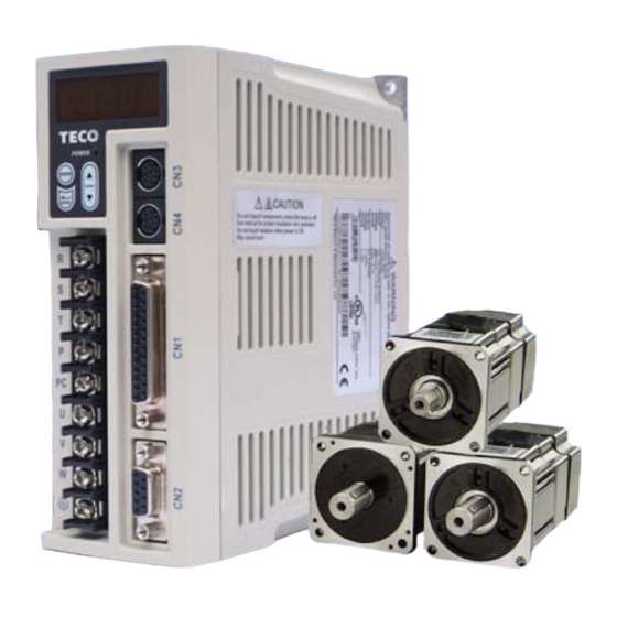
- Page 3 First of all, thank you for using TECO Servo Driver JSDEP Series (“JSDEP” for short) and Servo Motors. JSDEP can be controlled by digital board or PC, and provide excellent performance for a wide range of applications and different requirement from customers.
-
Page 4: Table Of Contents
Table of Contents Chapter 1 Checking and Installing 1-1 Checking Products ..........................1-1 1-1-1 Confirming with Servo Drives ....................1-1 1-1-2 Confirming with Servomotors....................1-2 1-1-3 Servo motor Model Code display ..................1-3 1-2 Surface and Panel Board ........................1-5 1-3 A Brief Introduction of Operation for Drives.................1-6 1-4 Conditions for Installation of Drives....................1-7... - Page 5 4-2 Trial Operation for Servomotor without Load from Host Reference .........4-5 4-3 Trial Operation with the Servomotor Connected to the Machine ..........4-8 Chapter 5 Control Functions 5-1 Control Mode Selection ........................5-1 5-2 Torque Mode ............................5-2 5-2-1 Analog Torque command Ratio ...................5-3 5-2-2 Adjusting the Analog Torque Command Offset ..............5-4 5-2-3 Torque Command Linear Acceleration and Deceleration ..........5-5 5-2-4 Definition of Torque Direction ....................5-6...
- Page 6 5-6-4 Brake Mode ..........................5-66 5-6-5 Timing Diagram of Mechanical Brake ................5-66 5-6-6 CW/CCW Drive Inhibit Function ..................5-68 5-6-7 Selecting for External Regeneration Resistor ..............5-69 5-6-8 Fan Setting ...........................5-71 5-6-9 Analog Monitor ........................5-72 5-6-10 Factory setting Paramerter ....................5-72 Chapter 6 Parameter Function 6-1 Explanation of Parameter Groups ....................6-1 6-2 Parameter Display Table ........................6-2 Chapter 7 Communications Function...
-
Page 7: Chapter 1 Checking And Installing
(The Servo Motor with Mechanical-Brake can not be rotated directly) There must be the “QC”-seal in each servo drive, if not, please do not proceed Power ON. If there is any bug or irregular under the situation above, please contact TECO’s Local sales representative or distributor instantly. -
Page 8: Confirming With Servomotors
1-1-2 Confirming with Servo Motors A – P S C 08 A H K B TECO AC Servo Machinery BK Product No. : No BK B:BK Motor Series: Spline Encode Grease Seal Series A IP67 (except shaft and connector) Inertia :... -
Page 9: Servo Motor Model Code Display
1-1-3 Servo motor Model Code display dn-08 (Servo motor Model Code display) Use dn-08 to display servo motor code and check the servo drive and motor compatibility according to the table below. If the dn08 preset is not according to the list below then contact your supplier. The motor model code is stored in parameter Cn30. - Page 10 dn-08 Display Motor Standards Encoder Drive Model Motor Model Cn030 Setting Specification Watt(KW) Speed(rpm) H1331 JSMA-PMB10AB 2000 2500 H1332 JSMA-PMB10AH 2000 8192 H1341 JSMA-PMH10AB 2500 JSDEP-30A 1500 H1342 JSMA-PMH10AH 8192 H1351 JSMA-PMC10AB 2500 3000 H1352 JSMA-PMC10AH 8192 H1511 JSMA-PMA15AB 2500 1000 H1512 JSMA-PMA15AH...
-
Page 11: Surface And Panel Board
1-2 Surface and Panel Board JSDEP-10A / 15A / 20A / 30A JSDEP-50A3 / 75A3 LED Display Heat sink Main Power Serial Input Terminal Communication Interface *External Regenerative Resistor Terminal I/ O Interface Motor Terminal Ground Terminal Motor Encoder Interface * Terminal P and PC can not be dosed... -
Page 12: A Brief Introduction Of Operation For Drives
Key Board 1-3 A Brief Introduction of Operation for Drives There are many kinds of control-mode. The detail modes display as fellow: Name Mode Explanation Position Mode Position control for the servo motor is achieved via an external (External Pulse pulse command. -
Page 13: Conditions For Installation Of Drives
1-4 Conditions for Installation of Drives 1-4-1 Environmental Conditions The product should be kept in the shipping carton before installation. In order to retain the warranty coverage, the AC drive should be stored properly when it is not to be used for an extended period of time. Some storage suggestions are: Ambient Temperature: 0 ~ + 55 ℃;... -
Page 14: Direction And Distance
1-4-2 Direction and Distance... -
Page 15: Conditions For Installation Of Servomotors
1-5 Conditions for Installation of Servo Motors 1-5-1 Environmental Conditions Ambient Temperature: 0 ~ + 40 ℃; Ambient humidity: Under 90% RH (No Frost). Storage Temperature: - 20 ~ + 60 ℃; Storage temperature: Under 90%RH (No Frost). Vibration: Under 2.5 G. In a well-ventilated and low humidity and dust location. -
Page 16: Notice For Install Motor
1-5-3 Notice for install motor 1. Please using oil-seal-motor to avoid the oil from reduction gear flowing into the motor through the motor shaft. 2. The cable need to be kept dry. 3. Please fixing the wiring cable certainly, to avoid the cable ablating or breaking. 4. -
Page 17: Chapter 2 Wiring
Chapter 2 Wiring 2-1 Basic Wiring for Servo System 2-1-1 Wiring for Main Circuit and Peripheral Devices... -
Page 18: Wiring For Servo Drives
2-1-2 Wiring for Servo Drives The wire material must go by “Wiring Specifications.” Wiring Length: Command Input Wire: Less than 3m. Encoder Input Wire: Less than 20m. The Wiring goes by the shortest length. Please wire according to the standard wiring schema. Don’t connect if no using. Please use the NFB to meet IEC (or UL Certification) between power supplier and servo drive. -
Page 19: Specifications Of Wiring
2-1-3 Specifications of Wiring Connection Terminal Servo Drives and Wire Specifications mm² (AWG) Connection Mark Name of Connect Terminal Terminal (Sign) 1.25 R、S、T Main Power Terminal (16) (14) (12) 1.25 U、V、W Motor Terminal (16) (14) (12) Terminal External regeneration 1.25 P、Pc resistance terminal (16) -
Page 20: Motor Terminal Layout
2-1-4 Motor Terminal Layout A Table of Motor-Terminal Wiring (1) General Joint: Terminal Symbol Color Signal White Black Green Fine red DC +24V Brake control wire Fine yellow (2) Military Specifications Joint (No Brake): Terminal Color Signal White Black Green (3) Military Specifications Joint (Brake): Terminal Color... - Page 21 Table of Motor-Encoder Wiring (1) General Joint: Terminal Symbol Color Signal White Black Green Blue Purple Yellow Orange Shield (2) Military Specifications Joint Terminal Symbol Color Signal White Black Green Blue Purple Yellow Orange Shield...
-
Page 22: Typical Wiring For Motor And Main Circuit
2-1-5 Typical Wiring for Motor and Main Circuit * The Wiring Example of Single Phase Main Power (Less than 1KW) * The Wiring Example of 3 Phase Main Power (More than 1KW) Power ON Power OFF MC/a White MC/R Black MC/S Power Filter Green... -
Page 23: Tb Terminal
2-1-6 TB Terminal Terminal Name Detail Sign Main circuit power input Connecting to external AC Power. terminal Single / 3 Phase 200~230VAC +10 ~ -15% 50/60Hz ±5% External regeneration resistance terminal Please refer to Cn012 to see resistance value, when using external regeneration resistance. -
Page 24: Wiring For Mechanical Brake
2-1-7 Wiring for Mechanical Brake Uninstall BRAKE: JSMA-S/L series: Use Red wire and yellow wire connecting to DC +24V voltage(No polarity) JSMA-M/H series: BK outputs from A & F of Motor Power Joint, servo motor can operate normally after uninstalling. JSMA-M/H JSMA-S/L Yellow Wire... -
Page 25: I/O Terminal
2-2 I/O Terminal There are 4 groups of terminals, which control signal terminal (CN1), encoder terminal (CN2) and communication connector (CN3/CN4). The diagram below displays all positions for the terminal. CN3, CN4 (Female) Communication Connector CN1 (25 pins Female) Control Signal Terminal CN2 (9 pins Female) Encoder Terminal... -
Page 26: Output Signals From The Servo Pack
2-2-1 Output Signals from the Servo pack (1) Diagram of CN1 Terminal: P.S.: 1. If there is unused terminal, please do not connect it or let it be the relay terminal. 2. The Shielded Wire of I/O cable should connect to the ground. 2-10... - Page 27 (2) CN1 Signal Name and Explanation: (a) General I/O Signal: Explanation of General I/O Signal Function Function Signal Name Pin No. Wired Mode Symbol Pulse Position Pulse Command Input /Pulse Sign Position Symbol Command Input /Sign Analog Signal Input Speed Command / Speed Limit Analog Signal Input Torque Command / Torque Limit Encoder Output A Phase...
- Page 28 Explanation of General I/O Signal Function Function Signal Name Mode I/O Operation and Function Symbol The Driver can receive 3 kinds of Command below: Pulse Position Pulse . (Pulse)+ (Sign) Command Input /Pulse . (CCW)/ (CW)Pulse Sign Position Sign .AB Phase pulse Command Input /Sign In Speed Mode, when external speed command is operated...
- Page 29 (b) Digital I/O Signal: For many kinds of application, the digital input/output terminal layouts of all operation modes are accordingly different. In order to provide more functions, our drives can provide multi terminal layout settings. Users can set these functions for application. Digital input terminal layout provides 6 (Pin1~13, 14~16) programmable terminal;...
- Page 30 Digital Input Function (Except CCWL and CWL are high electric potential, other terminal layout are low electric potential. Please refer to 5-6-1 to see related parameters) Function Signal Name Mode I/O Function Sign SON and IG24 close loop: Servo ON ; SON and IG24 open loop: Servo On Servo OFF.
- Page 31 Digital Input Function Explanation (Except CCWL and CWL are the high electric potential, other terminal layout are the low electric potential, please refer to 5-6-1 to check related parameters setting) Function Signal Name Mode I/O Function Symbol When MDC and IG24 close loop, current control mode will Control Mode Pe/S/T transform into default control mode, please refer to Cn001.
- Page 32 Digital Input Function Explanation (Except CCWL and CWL are the high electric potential, other terminal layout are the low electric potential, please refer to 5-6-1 to check related parameters setting) Function Signal Name Mode I/O Function Symbol Internal position command select : Internal Position POS1 POS2...
- Page 33 Digital Output Function Explanation (The terminal layout here from this explanation are all the low electric potential, please refer to 5-6-1 to check parameter settings) Function Signal Name Mode I/O Function Symbol Main power and control power input are normal. Under the Servo Ready situation of no alarm, terminal layouts RDY and IG24 close loop.
- Page 34 (3) CN1 Interface Circuit and Wire Mode: The diagram below introduces all interface circuit of CN1 and wire-method of host controller. (a) Digital input interface circuit (IO1): Digital input interface circuit can be operated by relay or collector transistor circuit. The relay should be the low electric current, in order to avoid the faulty contacting.
- Page 35 (c) Pulse Command Input Interface Circuit(IO3): Suggesting to use the input method of Line Driver to send the pulse command. The maximum input command frequency is 500kpps. Using the input method of Open Collector will cause the decrease of input command frequency, the maximum input command frequency is 200kpps.
- Page 36 (d) Encoder Output Interface Circuit (IO4): Encoder output interface circuit is the output method of Line Driver, please let end terminal resistance(R=200~330Ω) connect to Line Receiver input terminal. Encoder Output Interface Circuit (Line Driver) (e) Analog Input Interface Circuit (IO5): There is sometimes ripple inside the servo internal power.
-
Page 37: Encoder Connector (Cn2) Terminal Layout
2-2-2 Encoder Connector (CN2) Terminal Layout (1) Diagram of CN2 Terminal: P.S. Do not wire to the terminal, which is un-operated. 2-21... - Page 38 (2) Name and Explanation of I/O Signal: Encoder Output No. and Color General Plug-in Signal Name Code Terminal Layout Function Joint Joint 9 wires Output (fewer wiring) Power output 5V Power for encoder (provided from driver). white + Terminal When the cable is more than 20m, user should separately use 2 cables to avoid decreasing voltage of encoder.
-
Page 39: Typical Circuit Wiring Examples
2-3 Typical Circuit Wiring Examples 2-3-1 Position Control Mode (Pe Mode) (Line Driver) Notes: Pe mode =External pulse positioning command 2-23... -
Page 40: Position Control Mode (Pe Mode) (Open Collector)
2-3-2 Position Control Mode (Pe Mode) (Open Collector) Notes: Pe mode =External pulse positioning command 2-24... - Page 41 2-3-3 Position Control Mode (Pe Mode) (Pi Mode) Notes: Pi mode =internal position command 2-25...
- Page 42 2-3-4 Speed Control Mode (S Mode) 2-26...
- Page 43 2-3-5 Torque Control Mode (T Mode) 2-27...
-
Page 44: Chapter 3 Panel Operator / Digital Operator
Chapter 3 Panel Operator / Digital Operator 3-1 Panel Operator on the Drives The operator keypad & display contains a 5 digit 7 segment display, 4 control keys and two status LED displays. Power status LED (Green) is lit when the power is applied to the unit. Charge LED (Red) Indicate the capacitor ‘s charge status of main circuit. - Page 45 After power on, MODE button can be used to select 9 groups of parameter. By pressing the Mode key repeatedly once at a time you can scroll trough the displays below. LED Display after Step Description Operation Power on Drive status parameters. Diagnostic parameters.
- Page 46 Ex: Setting Speed Parameter Sn203 to 100rpm. LED Display after Step Description Operation Power On Display status of servo drive Press MODE-Key 6 times to select Sn 201 Press INCRMENT- Key twice Sn203 is displayed. To view the Sn203 preset value by press ENTER-Key for 2 seconds Shift to the second digit by press ENTER- Key once Shift to next Digit by press ENTER-Key once again...
- Page 47 Some of the data entry in this drive are in the format shown below, for these data the Most significant digit will be shown by the Capital letter “H” as shown below. Ex: Home search function in position mode Pn317 = 0212. Each digit of this preset for Pn317 parameter defines a selection for a specific function.
- Page 48 (2) If the negative value has 5 digits follow the steps in the example below: Ex: Pn317 (internal position preset command 1) set to a negative value -10000 revolutions. Control LED Display after Step Description Keys Operation Power On On” power on “ Drive Status parameter is displayed. Pressing MODE-Key 8 times, position parameter Pn 301 will be displayed.
- Page 49 (1) Speed and Torque control mode: The following table describes the digit and status code. Description Digit Digit Lighting Digit Off BASE BLOCK Servo OFF Servo ON Speed Reached Motor speed was greater than Motor speed was less than (INS) Cn007(Speed reached preset) Cn007(Speed reached preset) Speed Command...
- Page 50 (2) Position control mode: The following table describes the digit and status code. Description Digit Digit Lighting Digit Off BASE BLOCK Servo OFF Servo ON Position Complete Position error was less than Position error was greater than (INP) Pn307(Position complete value) Pn307(Position complete value) Speed Reached Motor speed was greater than...
-
Page 51: Signal Display
3-2 Signal Display 3-2-1 Status Display Following parameters can be used to display drive and motor Status. Parameter Display Unit Explanation Signal Un-01 Actual Motor Speed Motor Speed is displayed in rpm. It displays the torque as a percentage of the rated torue. - Page 52 Parameter Display Unit Explanation Signal Pulse command – After power on, it displays pulse command input Un-21 rotation value(High Byte) rotation number in High Byte value. Un-22 Position feedback pulse 2500/8192 ppr Encoder feedback (Absolute). ─ Un-23 Reserved Reserved ─ Un-24 Reserved Reserved...
-
Page 53: Diagnostic Function
3-2-2 Diagnostic function Following diagnostics parameters are available: Parameter Name and Function Signal Control mode display dn-01 dn-02 Output terminal status dn-03 Input terminal status dn-04 Software version (CPU version) dn-05 JOG mode operation dn-06 Reserved Auto offset adjustment of external analog comm dn-07 voltage Servo model code... - Page 54 dn-02 (Output terminal status) Use dn-02 to check the status of output terminals. Output status display is described below: When output terminal signal has a low logic level (close loop with IG24), the corresponding LED will be on. When output terminal signal has a high logic level (open loop with IG24), the corresponding LED will be off.
- Page 55 dn-04 (Version of Software) Use dn-04 to view the current software version of the Servo drive. Software version can be checked as below: Step Keys LED Display Description Power On On” power on Drive Status is displayed. Press MODE-Key twice to view diagnostics parameter dn-01.
- Page 56 dn-07 (Auto offset adjustment of external analog command voltage) If the external torque or speed analog command is set to 0V and the motor is rotating slowly, this is due to analog input zero offset, use dn-07 to auto adjust this offset and stop the motor rotating.
- Page 57 dn-08 (Servo motor Model Code display) Use dn-08 to display servo motor code and check the servo drive and motor compatibility according to the table below. If the dn08 preset is not according to the list below then contact your supplier. The motor model code is stored in parameter Cn30.
- Page 58 Motor Standards dn-08 Display Encoder Drive Model Motor Model Cn030 Setting Specification Watt(KW) Speed(rpm) H1331 JSMA-PMB10AB 2000 2500 H1332 JSMA-PMB10AH 2000 8192 H1341 JSMA-PMH10AB 2500 JSDEP-30A 1500 H1342 JSMA-PMH10AH 8192 H1351 JSMA-PMC10AB 2500 3000 H1352 JSMA-PMC10AH 8192 H1511 JSMA-PMA15AB 2500 1000 H1512 JSMA-PMA15AH...
-
Page 59: Chapter 4 Trial Operation
Chapter 4 Trial Operation Before proceeding with trial run, please ensure that all the wiring is correct. Trial run description below covers the operation from keypad and also from an external controller such as a PLC. Trial run with external controller speed control loop (analog voltage command) and position control loop (external pulse command). -
Page 60: Trial Operation For Servomotor Without Load
4-1 Trial Operation Servo motor without Load To carry out a successful trial run follow the steps below and ensure that drive wiring is correct and as specified. Warning In order to prevent potential damage,prior to trial run ensure that the driven mechanism, couplings and belts etc are disconnected from the motor. - Page 61 Steps for setting parameter Cn002.1 ( CCWL &CWL Rotation limit selection). Setp Keys LED Display Description Power on On” power on “ Drive Status is displayed. Press MODE-Key 4 times to display Cn001. Press INCREMENT-Key once to display Cn002. Press ENTER-Key for 2 secs to display the preset value of Cn002.
- Page 62 Steps for setting JOG function: Step Keys LED Display Description Power on On” power on “ Drive Status is displayed. Press MODE-Key twice to view diagnostics parameter dn-01. Press INCREMENT-Key 4 times to display dn-5. Press ENTER-Key for 2 seconds to enter JOG MODE. Motor will power on immediately.
-
Page 63: Trial Operation For Servomotor Without Load From Host Reference
4-2 Trial Operation for Servo motor without Load from Host Reference Check and ensure that all power connections to the drive and motor and control signal connection between the host controller and the drive are correct. Motor must be mechanically disconnected from the load. Following section describes the trial run when using a host controller such as a PLC. - Page 64 Trial run in Speed control mode(Cn001=1). 1. Wiring check: Check and ensure that all power cable and control signal connections are correct as shown below. To be able to adjust the speed for test connect a potentiometer between terminals SIN (analog input voltage) and AG (Analog Ground).
- Page 65 Position control mode trial run (Cn001=2). 1. Wiring: Check and ensure that all power connections to the drive and motor and control signal connections are correct as diagram below. 2. Setting electronic gear ratio. Set electronic gear ratio parameters Pn302~Pn306 as required for the positioning application. (refer to section 5-4-3).
-
Page 66: Trial Operation With The Servomotor Connected To The Machine
4-3 Trial Operation with the Servo motor Connected to the Machine Servo drive parameters must be set correctly otherwise damage to machinery and potential Injury may result. Do not close to the machine after temporary power loss, the machine may restart unexpected. Please take the measures highlighted in the section below before trial run with load. -
Page 67: Chapter 5 Control Functions
Chapter 5 Control Functions 5-1 Control Mode Selection There are three control modes in the servo drive, torque, speed and position modes can be selected individually or as a combination according to the selection table below: Default Control Parameter Name Setting Description Value... -
Page 68: Torque Mode
5-2 Torque mode Torque mode is used in applications such as printing machines, coil wiring machines, injection molding machines and specific application that requiring torque control. Diagram below shows the torque control process diagram. Analog voltage torque command is applied to the drive input terminals as shown below: Caution! Care should be taken in selection of required torque direction CW/CCW. -
Page 69: Analog Torque Command Ratio
5-2-1 Analog Torque command Ratio Analog torque command ratio can be used to adjust the relationship between Input voltage torque command and actual torque command. Parameter Name Default Unit Setting range Control Mode Analog torque Tn103 %/10V 0~600 command ratio Setting example: refer to the following diagram. -
Page 70: Adjusting The Analog Torque Command Offset
5-2-2 Adjusting the analog torque command offset For a torque command of 0V, motor could possibly be rotating slowly. To rectify this effect by adjust offset value in parameter Tn104 or use auto offset adjust feature. (Please refer to section 3-2-2). Note: To check and set the offset to zero, insert a link between analog torque command contact SIC (CN1-12) and analog ground contact AG (CN1-13). -
Page 71: Torque Command Linear Acceleration And Deceleration
5-2-3 Torque command linear acceleration and deceleration A smooth torque command can be achieved by enabling acceleration/Deceleration parameter Tn101 Setting Control Parameter Name Setting Description range mode Disable ★ Linear acceleration/ Enable │ deceleration method Tn101 Enable Torque command smooth accel/decel time Constant. -
Page 72: Definition Of Torque Direction
5-2-4 Definition of torque direction In torque mode, torque direction can be defined by one of the following three methods. (1) Input contacts RS1, RS2. (torque command CW/CCW selectable by programmable input) (2) Parameter Cn004. (motor rotation direction ) (3) Input contact TRQINV. (reverse torque command) Caution ! All 3 methods can be active at the same time. -
Page 73: Internal Torque Limit
5-2-5 Internal Torque Limit In torque Control mode, user can set internal torque limit values as required. Set as below: Parameter Name Default Unit Setting range Control mode CCW Torque Cn010 0~300 command limit -300 CW Torque Cn011 -300~0 command limit -200 5-2-6 Limiting Servomotor Speed during Torque Control In torque control, input contacts SPD1 and SPD2 can be used for selecting one of the two... -
Page 74: Additional Torque Control Functions
5-2-7 Additional torque control functions Torque Output Monitor When the torque level in CW or CCW directions becomes greater than the value set in Tn108 (torque level monitor value), the output contact INT is active. Parameter Name Default Unit Setting range Control mode Torque output monitor Tn108... -
Page 75: Speed Mode
5-3 Speed Mode Speed Mode is necessary for applications that require precisely speed control, such as weaving, drilling and CNC type machines.Diagrams below shows the speed control system in two parts. First stage shows Speed processing and conditioning and the second stage shows the Speed controller. -
Page 76: Selection For Speed Command
5-3-1 Selection for speed command In Speed control, input contacts SPD1 and SPD2 can be used for selecting one of the two methods below for setting speed limits. (1) External Analog command (Default) : Analog signal is input from terminals SIC & AG (pins 12 &... -
Page 77: Analog Speed Command Ratio
5-3-2 Analog speed command Ratio Analog speed command ratio can be used to adjust the relationship between Input voltage speed command and actual speed command. Parameter Name Default Unit Setting range Control mode Analog speed Rated Sn216 rpm/10V 100~6000 command ratio Speed Setting Example: (1) With Sn216 set to 3000, a speed command input voltage of 10V, corresponds to... -
Page 78: Analog Reference For Speed Command Limit
5-3-4 Analog reference for speed command limit A maximum limit for analog speed can be set by Sn218. Parameter Name Default Unit Setting range Control mode Analog speed Rated rpm Sn218 100~4500 command limit x 1.02 5-3-5 Encoder Signal Output Servo motor encoder pulse signal can be output to a host controller to establish an external control loop. -
Page 79: Smoothing The Speed Command
TIME TIME 5-3-6 Smoothing the speed command Sn205 can be used to eliminate speed overshoot and motor vibration by selecting one of the acceleration /deceleration methods which is suitable for the application from the table below. Control Parameter Name Setting Description mode Disable accel/decel smooth function... - Page 80 Setting example: (1) To achieve 95% of speed command output in 30msec: 30(msec) Sn206 10(msec) ln(1 95%) (2) To achieve 75% of speed command output in 30msec: 30(msec) Sn206 22(msec) ln(1 75%) ln= Natural log Speed command linear acceleration/deceleration function: Set Sn205=2 to enable the use of speed command linear acceleration/deceleration function.
- Page 81 S-Curve Speed Command Acceleration/Deceleration: Set Sn205=3 to enable the use of S-Curve speed command ac/deceleration function. Parameter Name Default Unit Setting range Control mode S-Curve speed command Sn208 msec 1~1000 accel/decel time setting S-Curve speed command Sn209 msec 0~5000 acceleration time setting S-Curve speed command Sn210 msec...
-
Page 82: Setting Rotation Direction
5-3-7 Setting rotation direction Motor rotation direction in speed mode can be set by parameter Cn004 (Motor rotation direction) and input contact SPDINV according to the tables below. Caution! Both methods can be operated at the same time. Ensure that these parameters are set correctly for the required direction. Control Parameter Name... -
Page 83: Speed Loop Gain
5-3-8 Speed Loop Gain In speed mode there are two speed controller loops, with separate Gain (P) and integral (I) functions. Speed controllers 1 or 2 can be selected by setting one of the multi- function input terminals, to selection G-SEL or by setting one of the parameters Cn20-Cn24 as required. Please refer to section 5-3-11 section B for more details. -
Page 84: Notch Filter
5-3-9 Notch Filter The function of the Notch filter is to suppress mechanical system resonance. Resonance occurs due to low mechanical system rigidity (high springiness) of transmission systems used with servo motors such as couplings, bearings, lead screws, etc. Enter the mechanical system vibration (resonance frequency) in parameter Cn013 (Notch Filter frequency) and adjust Cn014 to set the filter bandwidth scaling factor. - Page 85 5-19...
-
Page 86: Torque Limit Of Speed Control Mode
5-3-10 Torque limit of speed control mode In speed mode, the motor torque limit input contact TLMT could be used to select one of the two methods below: (1) Internal toque limit: Using default Cn010 (CCW Torque command limit ) and Cn011 (CW Torque command limit ). -
Page 87: Gain Switched
5-3-11 Gain Switched PI/P control mode selection (Section A) Automatic gain 1& 2 switch (Section B) The selection of PI/P control mode switch and Automatic gain 1& 2 switch by parameters or from input terminals can be used in following conditions. (1) In speed control, to restrain acceleration/deceleration overshooting. - Page 88 (1) PI to P mode switch over by comparing Torque command. When the Torque command is less than Cn016 PI control is selected. When the Torque command is greater than Cn016 P control is selected.. As shown in diagram below: Speed Cn016 Torque Command...
- Page 89 (4) PI to P mode switch over by comparing Position Error value. When the Position Error value is less than Cn019 PI control is selected. When the Position Error value is greater than Cn019 P control is selected. As shown in diagram below: (5) PI to P mode switch over by PCNT input contact.
- Page 90 Control Parameter Name Default Unit Setting Range Mode Automatic gain 1& 2 Cn020 x0.2 msec 0~10000 Pi/Pe/S switch delay time. Automatic gain 1& 2 Cn021 switch condition 0~399 Pi/Pe/S (torque command) Automatic gain 1& 2 Cn022 switch condition 0~4500 Pi/Pe/S (speed command) Automatic gain 1&...
- Page 91 (2) Automatic gain 1&2 switch condition (by Speed command). When speed command is less than Cn022 Gain 1 is selected. When speed command is greater than Cn022 Gain 2 is selected. When Gain 2 is active and speed command becomes less than Cn022 system will automatically switch back to Gain 1 the switch time delay can be set by Cn020.
- Page 92 Automatic gain 1&2 switch condition (by Position error value ). When position error value is less than Cn024 Gain 1 is selected. When position error value is greater than Cn024 Gain 2 is selected. When Gain 2 is active and position error value becomes less than Cn024 system will automatically switch back to Gain 1 and the switch time delay can be set by Cn020.
-
Page 93: Other Functions
5-3-12 Other Functions When the speed level in CW or CCW directions becomes greater than the value set in Cn007 (Speed reached preset), the output contact INS operates. Speed reached preset Parameter Name Default Unit Setting Range Control Mode Signal Speed reached Rated rpm Cn007... - Page 94 To Zero the speed command according to preset level in Sn215 set Sn204 to selection 1. Parameter Control Name Setting Description Signal Mode No action Zero Speed Sn204 selection Regard Speed command as Zero. (According to Sn215 setting). Speed Command Previous Speed Command Zero speed preset level...
-
Page 95: Position Mode
5-4 Position mode Position control mode is used for high-precision applications on machinery such as machine tools. The Position control mode offers two methods of control. External pulse input position command Internal position command. In external pulse command input mode, the positioning command is signaled to the drive by a host Controller to achieve a fixed position. -
Page 96: External Pulse Command
5-4-1 External Pulse Command Four types of external position pulse command signals can be interfaced. These can be selected from the list below. Position pulse signal logic can be selected Positive or negative as required. Parameter Control Name Setting Description Signal Mode (Pulse)+(Sign) - Page 97 Two types of pulse command can be connected, (Open collector) and (Line driver). Please refer to section 2-2-1 for the pulse wiring method. Pulse command timing should be in accordance with the time sequence standard below. Pulse Command Time Sequence Diagram of Pulse Command Time Standard Types Line Driver:...
-
Page 98: Internal Position Command
5-4-2 Internal Position Command In internal position command mode, 16 preset position commands can be set by parameters (Pn401~Pn496), and can be activated by use of input contacts POS1 ~ POS5. Preset positions are programmable and can be selected according to the table below. Position Position POS5... - Page 99 Position Position POS5 POS4 POS3 POS2 POS1 Position Command Parameter Command Speed Parameter Rotation Number Pn467 Pn469 Pulse Number Pn468 Rotation Number Pn470 Pn472 Pulse Number Pn471 Rotation Number Pn473 Pn475 Pulse Number Pn474 Rotation Number Pn476 Pn478 Pulse Number Pn477 Rotation Number Pn479...
- Page 100 PTRG. (Position Trigger). Once any preset position is selected by input contacts POS1~POS5 then require a trigger signal (PTRG) from the input contact, enable PTRG to start operation. Diagram below shows an example for 4 different absolute encoders. Note: Input contacts status “1” (ON) and “0” (OFF) Please check section 5-6-1 to set the required high /Low signal levels (PNP/NPN) selection.
- Page 101 CLR (Clear position command). If the CLR input is activated when a position command is in process then the motor will stop immediately and the remaining positioning pulses will be cleared. Parameter Pn315 must be set to 1or 2 as required (refer to section 5-4-7).
-
Page 102: Electronic Gear
5-4-3 Electronic Gear Electronic gear ratio parameter can be used to scale the command output pulse. This would be useful in transmission applications where move distance per move command pulse has to be scaled due to mechanical requirements. Diagram and notes below describe the electronic gear ratio effect. Example of a transmission device and calculations that show the required number of pulses from a host controller to move the table by 10mm. - Page 103 Electronic Gear Ratio Calculation Follow the Steps below: 1. Define the requirements of the positioning system Establish the following: • Move distance per one revolution of load shaft. • Servo motor Encoder ppr (Pulse Per Revolution). (please refer to section 1-1-2 Servo Motor Standards).
- Page 104 4. Parameter Setting for Electronic Gear Ratio Setting gear ratio Numerator and denominator parameters: Numerator and denominator values of the calculated electronic gear ratio must be entered in the required parameters. These two values have to be integer and with a value within the specified range in the table below.
- Page 105 Electronic Gear Ratio setting examples Transmission System Setting Process 1. Main positioning specifications: a) Load Shaft(Ball Screw) pitch move distance per revolution= 5mm Ball Screw b) Motor Encoder ppr ( Pulse per revolution) = 2000pulses 2. Move distance per one pulse of move Command. Moving Distance of 1 Pulse Command =1μm 3.
- Page 106 5-4-4 Smooth Acceleration Using the One Time Smooth Acceleration/Deceleration of Position Command” It smoothes the position pulse command frequency. Parameter Name Default Unit Setting Range Control Mode Signal External Position command ★ msec 0~10000 Pi/Pe Pn313 Accel/Decel Time Constant ★ New setting will become effective after re-cycling the power.
- Page 107 S-curve time constant of the Internal Position Command S-curve time constant generator can smoothen the command, it provides continuous speed and acceleration, which not only is better the motor characteristic of acc/dec but also helps the motor to operate more smoothly in machinery structure.S-curve time constant generator is only applicable to the mode of internal position command input.
- Page 108 x(t) v(t) a(t) j(t) S-Curve trip time definition 5-42...
-
Page 109: Definition Of Direction
5-4-5 Definition of Direction In position mode, user can use Pn314 (Position Command Direction Definition) to define motor rotation direction. The setting is showed as follow: Parameter Control Name Setting Description Signal Mode Definition of position command direction (from Clockwise (CW) motor load end) ★... -
Page 110: Clear The Pulse Offset
5-4-7 Clear the Pulse Offset In position control mode, parameter Pn315 (Pulse Error clear mode) has three modes can be select. CLR input contact is used to clear the pulse error as required according to the list below. Control Parameter Name Setting Description... -
Page 111: Original Home
5-4-8 Original Home Home routine is used to find and set a reference point for correct positioning. To set a HOME reference position, one of input contacts ORG (external sensor input), CCWL, or CWL can be used. An encoder Z phase (marker pulse) can also be used as home reference and can be search by CW or CCW direction. - Page 112 Control Parameter Name Setting Description Mode Once the Home Reference switch or signal is detected, motor reverses direction in 2 speed to find the nearest Z Phase pulse and sets this as the Home position, Once Reference then stops in accordance with Pn317.3 setting method. Home switch or Once the Home Reference switch or signal is detected, Signal, is found...
- Page 113 Additional Home routine parameters Home search speed parameters 1st (Fast) and 2 (Slow) speeds are set according to table below: Parameter Name Default Unit Setting Range Control Mode Signal preset high speed of Pn318 0~2000 Pi/Pe HOME Pn319 preset low speed of HOME 0~500 Pi/Pe Parameters Pn320 and Pn 321 provide Home position offset feature for applications...
- Page 114 Home Routine Speed /Position Timing Charts Following Sections Show the Speed/Position Timing charts according to Pn 317.0 and Pn317.1 selections. Pn317.0 Pn317.1 No Home routine Pn317.0=0 or 2 (After starting HOME routine, run CCW in 1 preset high speed for HOME Reference (CCWL, CWL or ORG).
- Page 115 Pn317.0=1or 3. After starting the HOME routine, run CW in 1 preset high speed to search for HOME Reference (CWL, CCWL or ORG). Pn317.1=0 . After finding HOME Reference, reverse direction in 2 preset low speed to search for the nearest Z Phase pulse to be set as the HOME position.
- Page 116 Pn317.0=3(After Starting HOME routine, run CW in 1 preset high speed to search for HOME Reference. (ORG) Pn317.1=1. After finding HOME Reference, continues in the same direction in 2 preset low speed to find the nearest Z Phase to be set as the HOME position. Pn317.2=2 Input Contact SHOME Starts the HOME routine.
- Page 117 Pn317.0=3. After Starting HOME routine, run CW in 1 preset high speed to search for HOME Reference.( ORG). Pn317.1=2. After Finding the HOME Reference, the Rising Edge of ORG sets the HOME Position. Pn317.2=2 Input Contact SHOME Starts the HOME routine. Pn317.3=0 Reverse search for HOME position Speed Pn319 (2...
- Page 118 Pn317.0=5. After Starting HOME routine, run CW in 1 preset high speed to search for the nearest Z phase pulse. Pn317.1=2. After Finding the Z phase pulse, set this position as the HOME position. Pn317.2=2 Input Contact SHOME Starts the HOME routine. Pn317.3=0 Reverse search for HOME position Speed Pn319 (2...
-
Page 119: Other Position Function
5-4-9 Other Position Function In position (Position Complete) As long as the position error value (counts) is less than the pulse counts set in Pn307 (Position Complete value) then INP output contact will be activated. Control Parameter Name Default Unit Setting Range Mode Pn307... -
Page 120: Gain Adjustment
5-5 Gain Adjustment The Servo controller provides 3 control loops as diagram shown below. Control methods are: Current Control, Speed Control and Position Control. Speed Host Power Position Current Controllor Controllor Circuit Controllor Controllor Diagram above shows the three control loops. Current (Inner loop), Speed (middle loop) and position (outer loop). - Page 121 Speed Loop Gain Speed Loop Gain has a direct effect on the response Bandwidth of Speed Control Loop. Under the condition of no vibration or noise, when higher is the Speed Loop Gain Value is setting speed response is becoming faster. If Cn025 (Load Inertia Ratio) is correctly set, then Speed Loop Bandwidth = Sn211 (Speed Loop Gain1) or Sn213 (Speed Loop Gain2).
- Page 122 Position Loop Gain Position Loop Gain has a direct effect on the response speed of Position Loop. Under the condition that there is no vibration or noise from servo motor, increasing the Position Loop Gain Value can enhance the response speed and hence reduce the positioning time.
-
Page 123: Automatic Adjusting
5-5-1 Automatic Adjusting This device provides ON-LINE Auto tuning, which can quickly and precisely measure Load Inertia and adjust the Gain automatically. Setting is according to the table below: Control Parameter Name Setting Description Mode Auto tuning Disabled Cn002.2 Auto tuning Pe/Pi/S Enable Auto tuning When Cn002.2 is set to 0 (Auto tuning Disabled), following Gain adjust parameters must... - Page 124 Rigidity Setting When Auto tuning is used, set the Rigidity Level depending on the various Gain settings for applications such as those listed below: Rigidity Position Loop Speed Loop Speed-loop Integral Mechanical Setting Gain Gain time constant 1 Application Rigidity Cn026 Pn310 [1/s] Sn211 [Hz]...
- Page 125 Process for Auto tuning The Diagram below shows the process for Auto tuning. Note: After Auto tuning is complete Set 0 in Cn002.2, otherwise it will not record the present measured Load Inertia Ratio. If the power is cut off during Auto tuning then when the power is established, Servo controller will use the previously recorded setting of Load Inertia Ratio which is stored in parameter Cn025.
-
Page 126: Manual Adjusting
5-5-2 Manual Adjustting Manual Gain adjustment is made available for applications when auto tune is not providing a good and stable system response, Or a system where there is no significant load variations and the auto tune is not used. Manual Gain Adjustment in Speed control Mode Step 1: Set Rigidity level in parameter Cn 26 (See section 5-5-1 for the selection table) and Cn25. -
Page 127: Improving Resonance
5-5-3 Improving Resonance The Servo drive provides the function of Gain Switching and Position Loop Feed-Forward Gain to improve system response. Note: Both of these features must be used correctly to improve system response, otherwise the response will become worse. Refer to the description below: Gain Switch Following Gain Switching features are provided:- a) Speed Loop Gain PI/P Switching... -
Page 128: Other Functions
5-6 Other Functions 5-6-1 Programmable I/O Functions Digital Inputs There are 6 DI (Digital Inputs) contacts and 3 DO (Digital Outputs) contacts which are programmable as listed below: Control Parameter Name Setting Description Mode Signal Contactor Function Null Non-function Servo On ALRS Alarm Reset PCNT... - Page 129 Parameter Control Name Setting Description Signal Mode Input contact state. NO (Normally Open). ★ Connecting (IG24) to inputs, enables the DI-1 Hn601.2 selected function. Logic State Input contact state. NC (Normally Closed). NO/NC Selection Disconnecting (IG24) from inputs, enables the selected function. ...
- Page 130 Digital Outputs. There are 4 programmable Digital Outputs according to the table below: Control Parameter Name Setting Description Mode Code Contactor functions Servo Ready Alarm Zero Speed Brake Signal ★ In Speed Hn613.0 DO-1 Logic In Position Hn613.1 state HOME HOME In Torque 09~0E...
-
Page 131: Switch For The Control Mode
5-6-2 Switch for the Control Mode Set one of the programmable input terminals to MDC (Control mode) selection. The input then will select the preset control mode, which is set by Parameter Cn001. Selections are listed below Control Parameter Name Setting Description Mode... -
Page 132: Brake Mode
5-6-4 Brake Mode Brake function for servo motor and the external mechanical brake if it is used can be set according to the table below. Set the brake mode as required for Servo off, Emergency Stop and CCW/CW rotation inhibit functions. Control Parameter Name... - Page 133 Timing for Brake output signal Set the required time for the operation of brake output signal (BI) according to the following. BI output can be used to control the function of an external electro-mechanical brake. Parameter Name Default Default Setting Range Control Mode Output time setting for Cn003...
-
Page 134: Cw/Ccw Drive Inhibit Function
5-6-6 CW/CCW Drive Inhibit Function Stopping method of the servo motor as a result of CW/CCW Inhibit function can be selected according to the list below: Control Parameter Name Setting Description Mode When torque limit reached the setting value of (Cn010,Cn011), servo motor deceleration to stop in the zero clamp status. -
Page 135: Selecting For External Regeneration Resistor
5-6-7 Selecting for External Regeneration Resistor In applications where a high inertia load is stopped rapidly, motor will generate an energy, which is regenerate power back to the servo drive (Regeneration energy) (1) Short deceleration time with heavy loads. (2) In vertical load applications. (3) High inertia rotary load applied to the motor shaft. - Page 136 Wiring for External Regeneration Resistor When external Regeneration Resistor is used, must remove the link between PC and P1 on TB1 Terminal. Then the resistor should be installed between terminals P and PC. For safety, use of resistors with thermal protection is recommended. The thermal switch contact can then be interlocked to disable drive or remove power if necessary.
-
Page 137: Fan Setting
Step Item Formula Description : Working Energy of Servo system (J) : Inertia applied to the motor shaft Calculate the working Energy of ω the servo system. • m ω : Motor running Speed(rpm) : The Energy during deceleration (J) Calculate the Energy π... -
Page 138: Factory Setting Paramerter
5-6-9 Low Voltage Protection auto-reset Control Parameter Name Setting Description Mode As servo on, it shows AL-01 low voltage alarm immediately when it detect low voltage, and after Low Voltage eliminating the situation, to reset it, servo off is a Cn031.1 Protection(AL-01) must. -
Page 139: Chapter 6 Parameter Function
Chapter 6 Parameter 6-1 Explanation of Parameter groups There are 10 groups of parameters as listed below. Symbol Description Un-xx Status Display Parameters. dn-xx Diagnostics Parameters. AL-xx Alarm Parameters Cn-xx System Parameters Tn1xx Torque Control Parameters Speed Control Parameters Sn2xx Pn3xx Position Control Parameters Point to Point Control... -
Page 140: Parameter Display Table
6-2 Parameter Display Table System Parameters Communication Setting Control Parameter Name & Function Default Unit Address Range Mode RS232 RS485 Control Mode selection Setting Explanation Torque Control Speed Control External Position Control (external pulse Command) External Position/Speed Control Switching ★● Speed/Torque Control Switching │... - Page 141 Communication Setting Control Parameter Name & Function Default Unit Address Range Mode RS232 RS485 Output time setting for Mechanical Brake Signal Brake Signal Timing Sequence: -2000 Cn003 msec │ 511H 0003H 2000 Implementation a pin for dynamic brake signal(BI) as a output signal before to perform this function.
- Page 142 Communication Setting Control Parameter Name & Function Default Unit Address Range Mode RS232 RS485 Encoder pulse output scale. For default set to the rated encoder number of pulses per revolution, such as 2500ppr. 2500 Encoder ppr can be scaled by setting a ppr in the range │...
- Page 143 Communication Setting Control Parameter Name & Function Default Unit Address Range Mode RS232 RS485 PI/P control switch mode. Setting Explanation Switch from PI to P if the torque command is larger than Cn016. Switch from PI to P if the speed command is larger than Cn017.
- Page 144 Communication Setting Control Name & Function Default Unit Parameter Address Range Mode RS232 RS485 Automatic gain 1& 2 switch delay time. Cn020 Speed loop 2 to speed loop 1, Change over delay, │ 53CH 0014H msec when two control speed loops ( P&I gains 1 & 2) are 10000 used.
- Page 145 Communication Setting Control Parameter Name & Function Default Unit Address Range Mode RS232 RS485 Rigidity Setting When Auto tuning is used, set the Rigidity Level depending on the various Gain settings for applications such as those listed below: Explanation Position Speed Speed Loop Loop Gain...
- Page 146 Communication Setting Control Parameter Name & Function Default Unit Address Range Mode RS232 RS485 Motor series selection ● Setting Explanation Cn031.3 50EH 001FH │ The existing motor 01 motor(only for mainland China) Speed feedback smoothing filter Cn032 │ 546H 0020H Restrain sharp vibration noise by the setting and 2500 this filter also delay the time of servo response.
- Page 147 Communication Setting Control Address Parameter Name & Function Default Unit Range Mode RS232 RS485 Communication protocol Setting Explanation 7 , N , 2 ( Modbus , ASCII ) 7 , E , 1 ( Modbus , ASCII ) 7 , O , 1 ( Modbus , ASCII ) ★...
- Page 148 Communication Setting Control Address Parameter Name & Function Default Unit Range Mode RS232 RS485 Drive warning setting Parameter Cn054 set by hex code, and each bit represents for each alarm. Setting the corresponding bit to 1 for the alarm is a warn mode.
- Page 149 Torque-Control Parameter Communication Setting Control Address Parameter Name & Function Default Unit Range Mode RS232 RS485 Linear acceleration/deceleration method Setting Explanation ★ Disabled. C8CH 0101H │ Tn101 Enabled. Enable Torque command smooth accel/decel time Constant. Linear accel/decel time period. Time taken for the torque-command to linearly accelerate to the rated torque level or Decelerate to zero torque .
- Page 150 Communication Setting Control Parameter Name & Function Default Unit Address Range Mode RS232 RS485 Preset Speed Limit 2. ( Torque control mode) In Torque control, input contacts SPD1 and SPD2 can be used to select Preset speed limit 2. As follows: 527H 0106H...
- Page 151 Speed-Control Parameter Communication Setting Control Parameter Name & Function Default Unit Address Range Mode RS232 RS485 Internal Speed Command 1 In Speed control, input contacts SPD1 and SPD2 can be used to select 3 sets of internal speed -4500 command, select for speed command 1 contact Sn201 │...
- Page 152 Communication Setting Control Parameter Name & Function Default Unit Address Range Mode RS232 RS485 Speed command smooth accel/decel time Constant. Set Sn205=1 to enable this function then set the time period for the speed to rise to 63.2% of the full speed. Sn206 msec 52BH 0206H...
- Page 153 Communication Setting Control Parameter Name & Functions Default Unit Address Range Mode RS232 RS485 Speed loop Gain 1 Speed loop gain has a direct effect on the frequency response bandwidth of the Speed-control loop. Sn211 │ 530H 020BH Without causing vibration or noise Speed-loop-gain can 1500 be increased to obtain a faster speed response.
- Page 154 Position Control Parameter Communication Setting Control Parameter Name & Function Default Unit Address Range Mode RS232 RS485 Position pulse command selection Setting Explanation ★ (Pulse)+(Sign) Pn301.0 │ (CCW)/(CW) Pulse AB-Phase pulse x 2 AB-Phase pulse x 4 Position- Pulse Command Logic ★...
- Page 155 Communication Setting Control Parameter Name & Function Default Unit Address Range Mode RS232 RS485 Electronic Gear Ratio Numerator 4 Use input contacts GN1 & GN2 to select one of four electronic Gear Ratio Numerators. To select Numerator 4, the statue of the input-contacts Pn305 │...
- Page 156 Communication Setting Control Name & Function Default Unit Parameter Address Range Mode RS232 RS485 Position command smooth Acceleration/Deceleration Time Constant Set the time period for the Position command pulse frequency to rise from 0 to 63.2%. Position Pulse Command Frequency (%) Position Pulse Command Frequency ★...
- Page 157 Communication Setting Control Parameter Name & Function Default Unit Address Range Mode RS232 RS485 Encoder Feedback Dividing Phase Leading Selection ★ Pn316.2 │ Setting Explanation Encoder feedback phase A leading phase B Encoder feedback phase B leading phase A. 50DH 0310H Encoder Feedback Dividing ★...
- Page 158 Communication Setting Control Parameter Name & Function Default Unit Address Range Mode RS232 RS485 Setting for HOME routine Setting Explanation Once the home routine is activated , motor will search for Home position in 1 speed in CCW direction and sets the Home reference position as soon as the nearest Z (marker pulse) is detected.
- Page 159 Communication Setting Control Parameter Name & Function Default Unit Address Range Mode RS232 RS485 Setting of stopping mode after finding Home signal. Setting Explanation After detecting the Home signal, it sets this position to be the Home reference (Un-16 encoder feed back rotating number and Un-14 encoder feed back pulse number are all 0), Pn317.3...
- Page 160 Communication Setting Control Parameter Name & Function Default Unit Address Range Mode RS232 RS485 S-Curve Time Constant for Internal Position Pn323 command(TACC) x0.4ms │ 52EH 0317H 5000 Please refer to Pn322 Pn324 Reserved ~Pn328 Pulse command smoothing filter C78H 031EH Pn329 │...
- Page 161 Internal Position Control Parameter Communication Setting Control Address Parameter Name & Function Default Unit Range Mode RS232 RS485 Internal Position Command 1 – Rotation Number -16000 Set the Rotation number of the internal Pn401 │ 568H 0701H Position Command 1 16000 Use input contacts POS1~POS5 to select Refer to 5-4-2.
- Page 162 Communication Setting Control Address Parameter Name & Function Default Unit Range Mode RS232 RS485 -16000 Internal Position Command 6 -Rotation Pn416 57CH 0715H Number │ 16000 Please refer to Pn401 -131072 Internal Position Command 6-Pulse 57EH 0716H Pn417 Number pulse │...
- Page 163 Communication Setting Control Parameter Name & Function Default Unit Address Range Mode RS232 RS485 Internal Position Command 12-Rotation -16000 Pn434 594H 072DH Number │ 16000 Please refer to Pn401 Internal Position Command 12-Pulse Number -131072 596H 072EH Pn435 pulse │ 597H 072FH Please refer to Pn402...
- Page 164 Communication Setting Control Address Parameter Name & Function Default Unit Range Mode RS232 RS485 Internal Position Command 18 - Pulse Number -131072 5AEH 0746H Pn453 pulse │ 5AFH 0747H Please refer to Pn402 131072 Internal Position Command 18 - Move Speed Pn454 │...
- Page 165 Communication Setting Control Address Parameter Name & Function Default Unit Range Mode RS232 RS485 Internal Position Command 24 - Move Speed Pn472 5C5H 0760H │ Please refer to Pn403 3000 Internal Position Command 25 -Rotation Number -16000 Pn473 5C8H 0761H │...
- Page 166 Communication Setting Control Address Parameter Name & Function Default Unit Range Mode RS232 RS485 Internal Position Command 31 -Rotation Number -16000 Pn491 5E0H 0779H │ Please refer to Pn401 16000 Internal Position Command 31 - Pulse Number -131072 5E2H 077AH Pn492 pulse │...
- Page 167 Quick Set-up Parameters Communication Setting Control Parameter Name & Function Default Unit Address Range Mode RS232 RS485 Speed Loop Gain 1. ( Same function as Sn211) Speed loop gain has a direct effect on the frequency response bandwidth of the Speed-control loop. ◆...
- Page 168 Multi-Function Input Parameters All digital inputs D1 to D12 are programmable and can be set to one of the funhctions listed below. Hn 601 which includes Hn 601.0 ,Hn601.1, Hn601.2 is used for digital input 1 ( D1-1). Hn602 to Hn613 are used for setting digital inputs 2 to 12.( D1-2 to D1-12). Communication Setting Control...
- Page 169 Communication Setting Control Name & Function Default Unit Parameter Address Range Mode RS232 RS485 DI-6 ★ C28H 0506H │ Hn606 Please refer to Hn601 DI-7 (only for communication control) ★ C29H 0507H │ Hn607 Please refer to Hn601 DI-8 (only for communication control) ★...
- Page 170 Communication Setting Control Parameter Name & Function Default Unit Address Range Mode RS232 RS485 DO-2 ★ C48H 050EH │ Hn614 Please refer to Hn613 DO-3 ★ │ C49H 050FH Hn615 Please refer to Hn613 ★ Reserved Hn616 Warning! If any of programmable Outputs of DO-1 ~ DO-3 are set for the same type of function; then the logic state selection (NO or NC selection) for these outputs can not be the same type.
- Page 171 Display Parameter Communication Parameter Display Unit Explanation Address Signal RS232 RS485 Un-01 Actual Motor Speed 6E4H 0601H Motor Speed is displayed in rpm. It displays the torque as a percentage of the rated torue. Un-02 Actual Motor Torque 9B6H 0602H Ex: 20 are displayed.
- Page 172 Communication Parameter Display Unit Explanation Adress Signal RS232 RS485 Pulse command – rotation After power on, it displays pulse command input 8FAH 0615H Un-21 High Byte value(absolute value) rotation number in value. 6B0H 0616H Un-22 Position feedback pulse 2500/8192 ppr Encoder feedback. Un-23 Reserved ─...
- Page 173 Diagnosis Parameter Communication Parameter Name & Function Address RS232 RS485 dn-01 Selected control mode 6AFH dn-02 Output terminal signal status. 6CBH dn-03 Input terminal signal status. C42H dn-04 Software version dn-05 JOG mode operation C43H dn-06 Reserved Auto offset adjustment of external ana 5FCH dn-07 command voltage.
-
Page 174: Chapter 7 Communications Function
Chapter 7 Communications function 7-1 Communications function ( RS-232 & RS-485 ) The Servo drive provides RS232 communication. The description below shows the communication wiring and communication protocol. 7-1-1 Communication wiring RS-232 Wiring Driver terminal MD-Type 9Pins PC terminal D-Type 9Pins(female) Pin 4 and Pin 6 is a close loop Pin 7 and Pin 8 is a close loop... - Page 175 RS-485 Wiring RS-232 Driver terminal MD-Type 8Pins RS-232 / RS-485 Description Description Name Description Name Receive Data Serial transmission + Data + Serial transmission - Data - Ground Power Supply + VS Transmit Data Ground Serial transmission + Data + Serial transmission - Data - Power Supply...
- Page 176 RS-232/RS-485 communication parameter Setting Control Parameter Name & Function Default Unit Range Mode Servo ID number ★ When using Modbus for communication,each servo │ Cn036 units has to setting a ID number. repeated ID number will lead to communication fail. Modbus RS-485 braud rate setting Setting Explanation...
- Page 177 Parameter Setting Control Name & Function Default Unit Signal Range Mode Digital input control method selection. Select digital input (12 pins) control method by external terminal or communication. Convert Binary code to Hex code for setting this parameter. DI and binary bits table as below.
- Page 178 7-1-2 RS-232 Communication protocol and format Baud rate 9600bps (Selection by Cn037.1 ) Parity Data bit Stop bit ※ Symbol H in folling sentence is for Hex representation. (1) Read a word from servo drive Function code format: R5XxSs Xx : A request to read register “ Xx ” from slave device( Unit :Byte, Hex representation) Ss : Check Sum Ss =’R’+’5’+’X’+’x’...
- Page 179 (3) Write a word to drive Function code format: W5XxYyZzSs Xx : Address for write data ( Unit :Byte、Hex representation) YyZz : Writes the data contents ( Unit :word, Hex representation) Ss : Check Sum,Ss =’W’+’5’+’X’+’x’+’Y’+’y’+’Z’+’z’ ( Unit :Byte, Hex representation) Ex3:Write data 0008H to register 30H ( Convert『W5300008』into ASCII codes ) Check Sum=57H+35H+33H+30H+30H+30H+30H+38H=1B7H...
-
Page 180: Modbus Communication Protocol For Rs-485
7-1-3 Modbus communication protocol for RS-485 The MODBUS protocol allows an easy communication within types of network architectures,before start to communication with slave device, set the ID number ( Cn036 ) for Servo drive respectively, server distinguish ID number for controlling specific client station. - Page 181 ASCII Mode Framing 10 bits Frame (7-bits Data) Start Stop Stop ←--- Data:7 bits ---→ ←------- Character Frame:10 bits -------→ Start Even Stop parity ←--- Data:7 bits ---→ ←-------- Character Frame:10 bits -------→ Start Stop parity ←--- Data:7 bits ---→ ←--------...
- Page 182 ASCII Mode Framing Symbol Name Description Comm. start 3AH, Char ’:‘ Include 2 ASCII code within 1-byte Comm. add : 1 ~ 254 convert to Hex representation ; Slave address Ex. Servo drive ADR is No.20 convert to 14H ; ADR = ’1‘...
- Page 183 Common function codes 03H : Read the register contents Continuous read N words. * Largest number of N is 29 (1DH) Ex.: Read two words ( register 0200H and 0201H ) from Slave address 01H. ASCII Mode Query PC Servo Response Servo PC OK) Servo...
- Page 184 06H : Write Single Register Write a word into register. Ex : Write data (0064H) into register address 0200H and slave ADR= 01 ASCII Mode Query PC Servo Response Servo PC (OK) Servo PC (ERROR) ‘ : ’ ‘ : ’ ‘...
- Page 185 08H : Diagnostic function The sub-function code 0000H is able to check communication signal between Master and Slaver. Data content is random value. Ex: Use the diagnostic function for ID=01H ASCII Mode Query PC Servo Response Servo PC (OK) Servo PC (ERROR) ‘...
- Page 186 10H : Write Multipile Registers Continuously write N words to register. * Largest number of N is 27 (1BH) Ex.: Write data (0064H) and (012CH) into register address 100H and 101H respectively. ASCII Mode Query PC Servo Response Servo PC (OK) Servo PC (ERROR) ‘...
- Page 187 RTU Mode Query PC Servo Response Servo PC (OK) Servo PC (ERROR) Function Code Function Code Function Code Exception (HI) (HI) Register Register code (Lo) (Lo) CRC(Lo) Data length Data length CRC(Hi) (word) (word) Byte counters CRC(Lo) Data (HI) CRC(Hi) 0100H (Lo) Data...
- Page 188 CRC Checking: CRC check code is from Slave Address to end of the data. The calculation method is illustrated as follow: (1) Load a 16-bit register with FFFF hex (all1’s). Call this the CRC register. (2) Exclusive OR the first 8-bit byte of the message with the low-order byte of the 16-bit CRC register, putting the result in the CRC register.
- Page 189 CRC Generation Function unsigned short CRC16(puchMsg, usDataLen) unsigned char *puchMsg ; /* message to calculate CRC upon*/ unsigned short usDataLen ; /* quantity of bytes in message*/ unsigned char uchCRCHi = 0xFF ; /* high byte of CRC initialized*/ unsigned char uchCRCLo = 0xFF ; /* low byte of CRC initialized*/ unsigned uIndex ;...
- Page 190 Low-Order Byte Table /* Table of CRC values for low-order byte */ static char auchCRCLo[] = { 0x00, 0xC0, 0xC1, 0x01, 0xC3, 0x03, 0x02, 0xC2, 0xC6, 0x06, 0x07, 0xC7, 0x05, 0xC5, 0xC4, 0x04, 0xCC, 0x0C, 0x0D, 0xCD, 0x0F, 0xCF, 0xCE, 0x0E, 0x0A, 0xCA, 0xCB, 0x0B, 0xC9, 0x09, 0x08, 0xC8, 0xD8, 0x18, 0x19, 0xD9, 0x1B, 0xDB, 0xDA, 0x1A, 0x1E, 0xDE, 0xDF, 0x1F, 0xDD, 0x1D, 0x1C, 0xDC, 0x14, 0xD4, 0xD5, 0x15, 0xD7, 0x17, 0x16, 0xD6, 0xD2, 0x12, 0x13, 0xD3, 0x11, 0xD1, 0xD0, 0x10, 0xF0, 0x30, 0x31, 0xF1, 0x33, 0xF3, 0xF2, 0x32, 0x36, 0xF6, 0xF7,...
-
Page 191: Chapter 8 Troubleshooting
Chapter 8 Troubleshooting 8-1 Alarm functions The Alarm codes are displayed in a format such as that shown below. For any Alarm messages , refer to this section for identify the cause and dispel the error. to reset the Alarm message by following pages description. If this is not possible for any reason then contact your local supplier for assistance. - Page 192 Example: Following table are procedures to access the alarm history record parameter. Steps LED Display Procedures Turn On On” power on “ Drive Status parameter is displayed. the Power Press MODE key to enter the Alarm History record. Press DOWN Key to view the Alarm 1 message that previously happened and the alarm code is “03”...
-
Page 193: Troubleshooting Of Alarm And Warning
8-2 Troubleshooting of Alarm and Warning Fault Status Digital Output Alarm Alarm Name Reset Corrective Actions Code and Description Method CN1-25 CN1-24 CN1-23 CN1-22 BB/A3 ST/A2 PC/A1 LM/A0 If there is no Alarm, CN1-22~CN1-25 — — Normal operates in accordance with default function. - Page 194 Alarm Status Digital Output Alarm Alarm Name Reset Corrective Actions Code and Description Method CN1-25 CN1-24 CN1-23 CN1-22 BB/A3 ST/A2 PC/A1 LM/A0 Encoder ABZ 1. Check the motor’s encoder phase signal connections. Reset error 2. Check the encoder if short circuit, Power Motor’s encoder poor solder joints or break.
- Page 195 Alarm Status Digital Output Alarm Alarm Name Reset Corrective Actions Code and Description Method CN1-25 CN1-24 CN1-23 CN1-22 BB/A3 ST/A2 PC/A1 LM/A0 Motor over speed 1. Reduce the speed command. Turn 2. Electronic gear ratio is incorrect Motor’s speed is ALRS check and set correctly.
- Page 196 Alarm Reset Methods 1. carry out the suggestions below to reset Alarm. (a) Reset by input signal : Once the cause of Alarm is rectified, disable SON signal (Switch off Servo ON), then activate input signal ALRS. Alarm condition should be cleared and the drive will be ready for operation. Reference 5-6-1 for setting SON and Alarm signal.
-
Page 197: Chapter 9 Specifications
Chapter 9 Specifications 9-1 Specifications and Dimension for Servo Drives Servo motor for 50A3 75A3 JSDEP-□□□ SC01 SC04 SC08 MA15 MB30 SC04* SC08* MA10 MB15 MC30 Available Servo Motor LC03 LC08 MB10 MC15 MH30 (Applicable Motor Models) JSMA-□□□□ ─ MA05 MC10 MB20 ─... - Page 198 Servo motor for 50A3 75A3 JSDEP-□□□ Homing Function Set by parameters Command Source External Analog Command / 3-Stage internal Speed Command External Voltage Range 0 ~ ±10Vdc / 0 ~ 4500rpm (Set by Parameters) Command Pulse Input 10KΩ Input Impedance Speed Control Range 1:5000(Internal speed command) / 1:2000(External analog command) ±0.03% or less at Load fluctuation 0 to 100% (at Rated Speed)
- Page 199 ※ Dimension for JSDEP-10A/15A/20A/30A Model JSDEP-10A/15A JSDEP-20A /30A Unit: mm Dimension for JSDEP-50A3 / 75A3 ※ Model JSDEP-50A3/ 75A3 Unit: mm...
-
Page 200: Specifications And Dimension For Servomotors
9-2 Specifications and Dimension for Servomotors Description for Servo Motor Type Number JSM A – P S C 08 A H K B TECO AC Servo Mechanical BK : Product Name : Without BK With Brake : Motor Series :... - Page 201 ※ Standard Specifications for JSMA-PSC/PLC JSMA-P□□□□ Motor Mode Symbol Unit SCP5 SC01 SC04 SC08 LC03 LC08 Drive Model 10A/15A 15A/20A 20A/30A Rated Output 0.05 0.75 0.75 N.m Rated Torque 0.16 0.32 1.27 2.39 0.95 2.39 N.m Max. Torque 0.48 0.95 3.82 7.16 2.86...
- Page 202 ※ Standard Specifications for JSMA-PM JSMA-P□□□□ Motor Mode Symbol Unit MA05 MA10 MA15 MH05 MH10 Drive Model 30A/50A3 Rated Output 0.55 0.55 N.m Rated Torque 5.25 9.55 14.32 3.50 6.40 N.m Max. Torque 15.76 28.65 42.96 10.51 19.21 Rated Speed 1000 1500 Max.
- Page 203 ※ Standard Specifications for JSMA-PM JSMA-P□□□□ Motor Mode Symbol Unit MB10 MB15 MB20 MB30 MC10 MC15 MC20 MC30 MH30 Drive Model 30A 30A/50A3 50A3 75A3 30A 30A/50A3 50A3 75A3 75A3 Rated Output N.m Rated Torque 4.78 7.16 9.55 14.33 3.20 4.78 6.37 9.55...
- Page 204 ※JSMA-PSC/PLC dimension diagram Motor Mode LC03AB/H ψ5.5 ψ100 ψ90 ψ14 ψ70 30 113.4 Without LC08AB/H ψ6.5 ψ112 ψ100 ψ16 ψ80 Brake LC08AB/H-0C ψ6.5 ψ112 ψ100 ψ19 ψ80 JSMA-PL Series LC03AB/H ψ5.5 ψ100 ψ90 ψ14 ψ70 30 147.8 With LC08AB/H ψ6.5 ψ112 ψ100 ψ16 ψ80 35 183.2 Brake...
- Page 205 ※ JSMA-PM/PH motor dimension diagram Motor Mode MA05 164.8 MH05 164.8 MA10 214.8 MB10 164.8 MC10 149.8 MH10 214.8 MA15 264.8 JSMA-PM Without JSMA-PH MB15 184.8 Brake Series MC15 164.8 MB20 214.8 MC20 184.8 MB30 264.8 MC30 214.8 MH30 13.5 114.3 HH30 13.5...
- Page 206 Motor Mode MA05 219.8 MH05 219.8 MA10 269.8 MB10 219.8 MC10 204.8 MH10 269.8 JSMA-PM With JSMA-PH MA15 319.8 Brake MB15 239.8 MC15 219.8 MB20 269.8 MC20 239.8 MB30 319.8 MC30 269.8 Unit: mm 9-10...
-
Page 207: Appendix A: Peripheral For Servo Motors
Appendix A: Peripheral for Servo motors App-1... - Page 208 App-2...
- Page 209 App-3...
Need help?
Do you have a question about the JSDEP Series and is the answer not in the manual?
Questions and answers