Table of Contents
Advertisement
Advertisement
Chapters
Table of Contents
Troubleshooting

Subscribe to Our Youtube Channel
Related Manuals for TECO JSDAP Series


Summary of Contents for TECO JSDAP Series
- Page 2 ■Warning and Caution: Warning Do not proceed to the assembly of the line while electrifying. Circuit & change components between entering shutting down the power supply and stopping showing CHARGE LED light of the Servo driver. The output of Servo drive [U, V, W] must NOT touch the AC power. ...
- Page 3 First of all, thank you for using TECO Servo Driver JSDAP Series (“JSDAP” for short) and Servo Motors. JSDAP can be controlled by digital board or PC, and provide excellent performance for a wide range of applications and different requirement from customers.
-
Page 4: Table Of Contents
Table of Contents Chapter 1 Checking and Installing ..................... 1 1-1 Checking Products ......................1 1-1-1 Confirming with Servo Drives ................. 1 1-1-2 Confirming with Servo Motors ................2 1-1-3 Servo motor Model Code display ................3 1-2 A Brief Introduction of Operation for Drives .............. 14 1-3 Conditions for Installation of Drives ................ - Page 5 3-3 OFF-LINE Auto tuning ....................40 Chapter 4 Parameter ........................ 45 4-1 Explanation of Parameter groups................45 4-2 Parameter Display Table ....................45 Chapter 5 Troubleshooting ....................... 86 5-1 Alarm functions ......................86 5-2 Troubleshooting of Alarm and Warning ..............87 5-3 Alarm Status Description .....................
-
Page 6: Chapter 1 Checking And Installing
There must be the “QC”-seal in each servo drive, if not, please do not proceed Power ON. If there is any bug or irregular under the situation above, please contact TECO’s Local sales representative or distributor instantly. 1-1-1 Confirming with Servo Drives JSD AP –15 A... -
Page 7: Confirming With Servo Motors
1-1-2 Confirming with Servo Motors A – P S C 08 A H K TECO AC Servo Machinery BK Product No. : No BK B: BK Motor Series: Grease Series A Encode Spline Seal IP67 (except shaft and connector) -
Page 8: Servo Motor Model Code Display
1-1-3 Servo motor Model Code display dn-08 (Servo motor Model Code display) Use dn-08 to display servo motor code and check the servo drive and motor compatibility according to the table below. If the collocation is discordant with that dn08 presented, reset parameter Cn030 or contact your supplier. - Page 9 dn-08 Display Drive Model Motor Standards Encoder Motor Model JSDAP Specification Cn030 Setting Watt(KW) Speed(rpm) H1121 JSMA-PLC03AB 2500 H1122 JSMA-PLC03AH 8192 H1125 15A(1) JSMA-PLC03A5 3000 15 bit(ABS) H1127 JSMA-PLC03A7 17 bit H112A JSMA-PLC03AA 17 bit(ABS) H1141 JSMA-SC04AB 2500 H1142 JSMA-SC04AH 8192 H1145 JSMA-SC04A5...
- Page 10 dn-08 Display Motor Standards Drive Model Encoder Motor Model JSDAP Specification Cn030 Setting Watt(KW) Speed(rpm) H1231 JSMA- (P)SC08AB 2500 H1232 JSMA-PSC08AH 8192 H1235 JSMA-PSC08A5 0.75 3000 15 bit(ABS) H1237 JSMA-PSC08A7 17 bit H123A JSMA-PSC08AA 17 bit(ABS) H1241 JSMA-PMA05AB 1000 2500 H1252 JSMA-PMH05AH 8192...
- Page 11 dn-08 Display Motor Standards Drive Model Encoder Motor Model JSDAP Specification Cn030 Setting Watt(KW) Speed(rpm) H132A JSMA-PMA10AA 1000 17 bit(ABS) H1331 JSMA-PMB10AB 2500 H1332 JSMA-PMB10AH 8192 H1335 JSMA-PMB10A5 2000 15 bit(ABS) H1337 JSMA-PMB10A7 17 bit H133A JSMA-PMB10AA 17 bit(ABS) H1341 JSMA-PMH10AB 2500 H1342...
- Page 12 dn-08 Display Motor Standards Drive Model Encoder Motor Model JSDAP Specification Cn030 Setting Watt(KW) Speed(rpm) H1511 JSMA-PMA15AB 2500 H1512 JSMA-PMA15AH 8192 H1515 JSMA-PMA15A5 1000 15 bit(ABS) H1517 JSMA-PMA15A7 17 bit H151A JSMA-PMA15AA 17 bit(ABS) H1521 JSMA-PMB15AB 2500 H1522 JSMA-PMB15AH 8192 H1525 JSMA-PMB15A5 2000...
- Page 13 dn-08 Display Motor Standards Drive Model Encoder Motor Model JSDAP Specification Cn030 Setting Watt(KW) Speed(rpm) H1711 JSMA-PMB30AB 2500 H1712 75A3 JSMA-PMB30AH 2000 8192 H1715 JSMA-PMB30A5 15 bit(ABS) H1717 JSMA-PMB30A7 17 bit 2000 H171A JSMA-PMB30AA 17 bit(ABS) H1721 JSMA-PMC30AB 2500 H1722 JSMA-PMC30AH 8192 H1725...
- Page 14 dn-08 Display Drive Model Motor Standards Encoder Motor Model JSDAP Specification Cn030 Setting Watt(KW) Speed(rpm) H1922 JSMA-PMH55AH 8192 1500 H1925 JSMA-PMH55A5 15 bit(ABS) H1927 JSMA-PMH55A7 17 bit 1500 H192A JSMA-PMH55AA 17 bit(ABS) 150A3 H1932 JSMA-PHH44AH 8192 H1935 JSMA-PHH44A5 15 bit(ABS) 2000 H1937 JSMA-PHH44A7...
- Page 15 dn-08 Display Drive Model Motor Standards Encoder Motor Model JSDAP Specification Cn030 Setting Watt(KW) Speed(rpm) H1A12 JSMA-PMH75AH Speed(rpm) H1A15 JSMA-PMH75A5 15 bit(ABS) H1A17 JSMA-PMH75A7 17 bit H1A1A JSMA-PMH75AA 17 bit(ABS) 200A3 Watt(KW) H1A22 JSMA-PHH55AH 8192 H1A25 JSMA-PHH55A5 15 bit(ABS) H1A27 JSMA-PHH55A7 17 bit H1A2A...
- Page 16 400V dn-08 Display Motor Standards Drive Model Encoder Motor Model JSDAP Specification Cn030 Setting Watt(KW) Speed(rpm) H1211 JSMA-PMB10BB 2500 H1212 JSMA-PMB10BH 8192 H1215 JSMA-PMB10B5 2000 15 bit(ABS) H1217 JSMA-PMB10B7 17 bit H121A JSMA-PMB10BA 17 bit(ABS) H1231 JSMA-PMB15BB 2500 H1232 JSMA-PMB15BH 8192 H1235 JSMA-PMB15B5...
- Page 17 dn-08 Display Motor Standards Drive Model Encoder Motor Model JSDAP Specification Cn030 Setting Watt(KW) Speed(rpm) H1341 JSMA-PMH30BB 2500 H1342 JSMA-PMH30BH 8192 H1345 JSMA-PMH30B5 1500 15 bit(ABS) H1347 JSMA-PMH30B7 17 bit H134A JSMA-PMH30BA 17 bit(ABS) H1401 JSMA-PMB30BB 2500 H1402 JSMA-PMB30BH 8192 H1405 JSMA-PMB30B5 2000...
- Page 18 dn-08 Display Motor Standards Drive Model Encoder Motor Model JSDAP Specification Cn030 Setting Watt(KW) Speed(rpm) H150A JSMA-PMH44BA 1500 17 bit(ABS) H1511 JSMA-PMH55BB 2500 H1512 JSMA-PMH55BH 8192 H1515 JSMA-PMH55B5 1500 15 bit(ABS) H1517 JSMA-PMH55B7 17 bit H151A JSMA-PMH55BA 17 bit(ABS) H1611 JSMA-PMH75BB 2500 H1612...
-
Page 19: A Brief Introduction Of Operation For Drives
1-2 A Brief Introduction of Operation for Drives There are many kinds of control-mode. The detail modes display as the followings: Name Mode Explanation Position Mode Position control for the servo motor is achieved via an external (External Pulse pulse command. Position command is input from CN1. Command) Position Mode Position control for the servo motor is achieved via by 16... -
Page 20: Conditions For Installation Of Drives
1-3 Conditions for Installation of Drives 1-3-1 Environmental Conditions The product should be kept in the shipping carton before installation. In order to retain the warranty coverage, the AC drive should be stored properly when it is not to be used for an extended period of time. Some storage suggestions are: Ambient Temperature: 0 ~ + 55 ℃;... -
Page 21: Direction And Distance
1-3-2 Direction and Distance... -
Page 22: Conditions For Installation Of Servo Motors
1-4 Conditions for Installation of Servo Motors 1-4-1 Environmental Conditions Ambient Temperature: 0 ~ + 40 ℃; Ambient humidity: Under 90% RH (No Moisture). Storage Temperature: - 20 ~ + 60 ℃; Storage temperature: Under 90%RH (No Moisture). Vibration: Under 2.5 G. -
Page 23: Notice For Installing Motor
1-4-3 Notice for installing motor 1. Please using oil-seal-motor to avoid the oil from reduction gear flowing into the motor through the motor shaft. 2. The cable need to be kept dry. 3. Please fixing the wiring cable certainly, to avoid the cable ablating or breaking. 4. -
Page 24: Chapter 2 Wiring
Chapter 2 Wiring 2-1 Basic Wiring for Servo System 2-1-1 Wiring for Main Circuit and Peripheral Devices 200V... - Page 25 400V...
-
Page 26: Wiring For Servo Drives
2-1-2 Wiring for Servo Drives The wire material must go by “Wiring Specifications.” Wiring Length: Command Input Wire: Less than 3m. Encoder Input Wire: Less than 20m. The Wiring goes by the shortest length. Please wire according to the standard wiring schema. Don’t connect if no using. ... -
Page 27: Specifications Of Wiring
2-1-3 Specifications of Wiring Connection Terminal Servo Drives and Wire Specifications mm² (AWG) Name of Connection Mark 100B Connect Terminal (Sign) Terminal 1.25 22.0 R、S、 Main Power (16) (14) (12) (10) (14) (14) (12) (12) (12) Terminal 1.25 14.0 22.0 U、V、... - Page 28 Connection Terminal Servo Drives and Wire Specifications Connection Position Position Name Terminal Number Position Command Input (Pulse、Sing、 14~17 /Pulse、/Sing) Encoder Signal Output 35~40 (PA、/PA、PB、/PB、 PZ、/PZ) 24V Open Collector Sign Input (EXT1、 41,42 EXT2) PW Output Terminal 5V (+5E) PW Grounding 0.2mm ²...
-
Page 29: Motor Terminal Layout
2-1-4 Motor Terminal Layout Table of Motor-Terminal Wiring (1) General Joint: Terminal Symbol Color Signal White Black Yellow / Green Fine White 1 Brake control wire Fine White 2 DC +24V (2) Military Specifications Joint (No Brake): Terminal Color Signal White Black... - Page 30 Table of Motor-Encoder Wiring For 15 bits / 17 bits Encoders (1) General Joint: Color Signal Terminal Symbol 15bits 17bits 15bits 17bits White Black Brown Brown/ Black Blue Blue/ Purple Black Shield (2) Military Specifications Joint Color Signal Terminal Symbol 15bits 17bits...
- Page 31 For 2500 / 8192 ppr Encoders (1) General Joint: Terminal Symbol Color Signal Black Blue Blue/ Black Green Green/ Black Yellow Yellow/ Black Shield (2) Military Specifications Joint Terminal Symbol Color Signal Black Blue Blue / Black Green Green / Black Yellow Yellow / Black Shield...
-
Page 32: Tb Terminal
2-1-5 TB Terminal Terminal Name Detail Sign 200V Connecting to external AC Power. Single Phase 200~230VAC +10 ~ -15% 50/60Hz ±5% Control circuit power input 400V terminal Connecting to external DC Power. Single Phase 24VDC ±10%. 200V ... -
Page 33: I/O Terminal
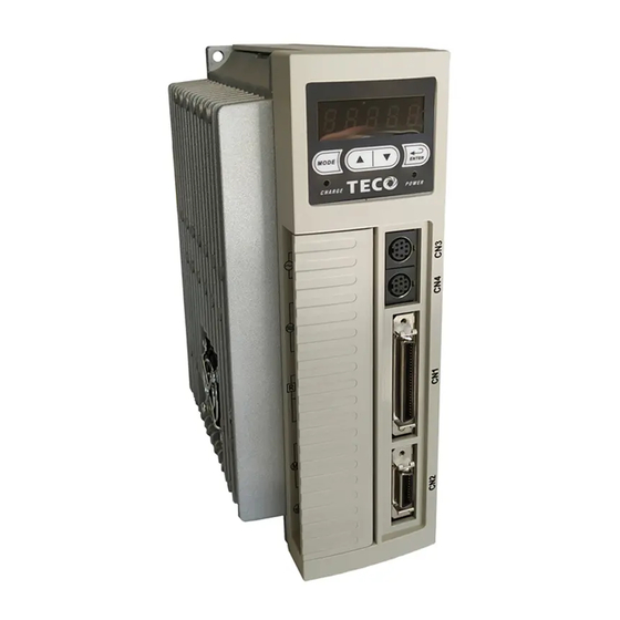
2-2 I/O Terminal There are 4 groups of terminal, which control signal terminal (CN1), encoder terminal (CN2) and communication connector (CN3/CN4). The diagram below displays all positions for the terminal. CN3、CN4 (8 pins Female)) Communication Connector CN1 Connector (Male) CN2 Connector (Male) -
Page 34: Output Signals From The Servo Pack
2-2-1 Output Signals from the Servo pack (1) Diagram of CN1 Terminal: Speed Control Speed Command DI-1 /Torque Control Speed Control Speed Limit Torque Limit DI-2 /Torque control Torque Analog Signal Command Ground DI-3 PI/P Switch Terminal Analog Signal DI-4 Ground Terminal Analog Monitor... -
Page 35: Encoder Connector (Cn2) Terminal Layout
2-2-2 Encoder Connector (CN2) Terminal Layout Diagram of CN2 Terminal: (a) Diagram of Fewer Wiring Type Encoder: (b) Diagram of 15 bits / 17 bits Encoder: Terminal Function Layout Power Supply Battery(+) Output Battery(-) Serial Data Ground output(+) Serial Data output(-) Notes: Do not wire to the terminal, which is un-operated. -
Page 36: Cn3/Cn4 Communication Terminal Layout
2-2-3 CN3/CN4 Communication Terminal Layout Diagram of CN3/CN4 terminal: Terminal Terminal Function Function Layout Layout Serial Data Received Ground Serial Data Transmission Data + Serial Data(+) Data + Serial Data(+) Data - Serial Data(-) Data - Serial Data(-) Notes: Do not wire to the terminal, which is un-operated. -
Page 37: Typical Circuit Wiring Examples
2-3 Typical Circuit Wiring Examples 2-3-1 Position Control Mode (Pe Mode) (Line Driver) Supply SERVO Filter RS232 r, 24V Control Power s, 0V Supply Regeneration resistor DC 24V IP24 Internal +24V DC DICOM Digital input common SERVO MOTOR DI-1 Servo ON (SON ) Encoder DI-4 CCW Limit ( CCWL ) -
Page 38: Position Control Mode (Pe Mode) (Open Collector)
2-3-2 Position Control Mode (Pe Mode) (Open Collector) Notes: 1. Pe mode =External pulse positioning command 2. DOCOM means common port of digital input (DOCOM must connect to IG24 when using internal power supply) -
Page 39: Position Control Mode (Pi Mode)
2-3-3 Position Control Mode (Pi Mode) SERVO Supply Filter RS232 r, 24V Control Power s, 0V Supply Regeneration resistor DC 24V IP24 Internal +24V DC Digital input DICOM common SERVO MOTOR DI-1 Servo ON (SON) Encoder DI-2 Alarm Clear(ALRS) DI-8 Position Trigger(PTRG) DI-9 Encoder Output A Phase... -
Page 40: Speed Control Mode (S Mode)
2-3-4 Speed Control Mode (S Mode) SERVO Supply Filter RS232 r, 24V Control Power s, 0V Supply Regeneration resistor DC 24V IP24 Internal +24V DC DICOM Digital input common SERVO MOTOR DI-1 Servo ON (SON) Encoder DI-4 CCW Limit ( CCWL) DI-5 ( CWL) CW Limit... -
Page 41: Torque Control Mode (T Mode)
2-3-5 Torque Control Mode (T Mode) Notes: 1. Pe mode =External pulse positioning command 2. DOCOM means common port of digital input (DOCOM must connect to IG24 when using internal power supply) -
Page 42: Turret Mode (Pt Mode)
2-3-6 Turret Mode (Pt Mode) Notes: 1. DOCOM means common port of digital input (DOCOM must connect to IG24 when using internal power supply) -
Page 43: Chapter 3 Panel Operator / Digital Operator
Chapter 3 Panel Operator / Digital Operator 3-1 Panel Operator on the Drives The operator keypad & display contains a 5 digit 7 segment display, 4 control keys and two status LED displays. Power status LED (Green) is lit when the power is applied to the unit. Charge LED (Red) Indicate the capacitor‘s charge status of main circuit. -
Page 44: Trial Operation
3-2 Trial Operation Before proceeding with trial run, please ensure that all the wiring is correct. Trial run description below covers the operation from keypad and also from an external controller such as a PLC. Trial run with external controller speed control loop (analog voltage command) and position control loop (external pulse command). -
Page 45: Off-Line Auto Tuning
3-3 OFF-LINE Auto tuning OFF-Line Auto tuning could automatic measuring the load characteristics and adjusts the appropriate control gain in a fixed-action stroke. Gain adjustment method based on the vibration detection, and the rigid table as a basis for the adjustment. In order to find the system gain limit, the machine would increase the gain until the system start to vibration, and then reduced the gain to be stable. - Page 46 OFF-Line adjustment will change the parameters as follows: Communication Defa Setting Control Parameter Name Unit Adress Range Mode RS232 RS485 Load-Inertia ratio LoadInerti aToMotor Cn025 x0.1 │ 5FBH 0019H LoadInerti aRatio 1000 MotorRotor Inertia(J Speed loop Gain 1 Speed loop gain has a direct effect on the frequency response bandwidth of the Speed-control loop.
- Page 47 Start The turns command of OFFLine-tuning (Cn60) The Maximum speed OFFLine-tuning (Cn61) OFFLine-tuning operation overtravel distance protection settings (Cn62) Set AutoTuning function choice (Cn59=1) Servo On Normal Display AL-09 Work? Deal problems by abnormal action Table The parameters: (Cn025) Load-Inertia ratio (Sn211)...
- Page 48 OFF-Line Autotuning abnormal action Table There are three reasons could cause AL09, including lack of runway, the system clock or long setting time. You could check by Un-47, and the description as follow. OFF-Line Autotuning abnormal action Table Error Reason Solution code Confirm if there is CW/CCW drive direction inhibit be triggered.
- Page 49 Rigidity Table: Rigidity Position Loop Speed Loop Speed-loop Integral Mechanical Setting Gain Gain time constant 1 Application Rigidity Cn026 Pn310 [1/s] Sn211 [Hz] Sn212 [x0.2msec] 1400 Machines driven by timing Belt, Chain or Gear: Large Moving Table, Conveyor Belt. The machines driven by Middle Ballscrew through decelerator: Ordinary...
-
Page 50: Chapter 4 Parameter
Chapter 4 Parameter 4-1 Explanation of Parameter groups There are 10 groups of parameters as listed below. Control Mode Code Alarm Description Code Signal Control Mode Un-xx Status Display Parameters. All Control Mode dn-xx Diagnostics Parameters. Position Control Mode(Internal Positional Command ) AL-xx Alarm Parameters Position Control Mode(External Puls Command) - Page 51 Display Parameter Communication Parameter Address Display Unit Explanation Signal RS232 RS485 Un-01 Actual Motor Speed 6C4H 0601H Motor Speed is displayed in rpm. It displays the torque as a percentage of the rated torue. Un-02 Actual Motor Torque 9B6H 0602H Ex: 20 are displayed.
- Page 52 Communication Parameter Display Unit Explanation Adress Signal RS232 RS485 Pulse command – rotation After power on, it displays pulse command input 8FAH 0615H Un-21 High Byte value(absolute value) rotation number in value. 6B0H 0616H Un-22 Position feedback pulse 2500/8192 ppr Encoder feedback. 15 bits encoder position it displays absolute position for an incomplete 9E7H...
- Page 53 System Parameters Communication Setting Control Parameter Name & Function Default Unit Address Range Mode RS232 RS485 Control Mode selection Setting Explanation Torque Control Speed Control External Position Control (external pulse Command) External Position/Speed Control Switching ★ ● Speed/Torque Control Switching │...
- Page 54 Communication Setting Control Parameter Name & Function Default Unit Address Range Mode RS232 RS485 Output time setting for Mechanical Brake Signal Brake Signal Timing Sequence: -2000 Cn003 msec │ 511H 0003H 2000 Implementation a pin for dynamic brake signal(BI) as a output signal before to perform this function.
- Page 55 Communication Setting Control Parameter Name & Function Default Unit Address Range Mode RS232 RS485 Encoder pulse output scale. 2500 For default set to the rated encoder number of pulses per revolution, such as 2500ppr. Encoder ppr can be scaled by setting a ppr in the │...
- Page 56 Communication Setting Control Address Parameter Name & Function Default Unit Range Mode RS232 RS485 CW/CCW drive inhibit mode Setting Explanation When torque limit reached the setting value of (Cn010,Cn011), servo motor deceleration to stop in the zero clamp condition. ★ Deceleration by using dynamic brake to stop then │...
- Page 57 Communication Setting Control Parameter Name & Function Default Unit Address Range Mode RS232 RS485 Automatic gain 1& 2 switch Setting Explanation Switch from gain 1 to 2 if torque command is greater than Cn021. Switch from gain 1 to 2 if speed command is greater than Cn022.
- Page 58 Communication Setting Control Address Parameter Name & Function Default Unit Range Mode RS232 RS485 Automatic gain 1& 2 switch condition (Torque command) Set Cn015.1=0 first. When torque command is less than Cn021 , Gain 1 is selected. Cn021 When torque command is greater than Cn021, Gain 2 is │...
- Page 59 Communication Setting Control Parameter Name & Function Default Unit Address Range Mode RS232 RS485 Rigidity Setting When Auto tuning is used, set the Rigidity Level depending on the various Gain settings for applications such as those listed below: Explanation Position Speed Speed Loop Setting...
- Page 60 Communication Setting Control Name & Function Default Unit Address Parameter Range Mode RS232 RS485 Analog monitor output 1, Offset adjustment Analog monitor output zero offset can be adjusted by parameter. Cn027 as below. -250 Cn027 │ C03H 001BH Analog monitor output 2, offset adjustment -250 Cn028 │...
- Page 61 Communication Setting Control Parameter Name & Function Default Unit Address Range Mode RS232 RS485 Motor Series Selection ● Setting Explanation Cn031.3 │ 50EH 001FH The existing motor 01 motor (only for mainland China) Speed feedback smoothing filter Cn032 Restrain sharp vibration noise by the setting and │...
- Page 62 Communication RS232 is read and written to the selection of EEPROM. ★ Setting Explanation Cn037.3 JSDAP Command address (E8~EC) │ 544H 0025H JSDAP Command address (70~74) * While setting to 1, Pn407~Pn410 are prohibited from applying. Communication protocol Setting Explanation 7 , N , 2 ( Modbus , ASCII ) 7 , E , 1 ( Modbus , ASCII ) 7 , O , 1 ( Modbus , ASCII )
- Page 63 Communication Setting Control Address Parameter Name & Function Default Unit Range Mode RS232 RS485 Low voltage protection level Set the delay time of Cn052, which triggers low Cn051 Volt │ 5F0H 0033H voltage protection alarm, when voltage of drive input power is lower than Cn051. Low voltage protection alarm delay time x250 Set the delay time of Cn052, which triggers low...
- Page 64 Communication Setting Control Address Parameter Name & Function Default Unit Range Mode RS232 RS485 The Sencond torequ command restriction for CCW direction Cn056 0~300 C05H 0038H The same description as Cn010 P.S.)The default would depends on Cn030 The Sencond torequ command restriction for CW -300 direction -260...
- Page 65 Communication Setting Control Parameter Name & Function Default Unit Address Range Mode RS232 RS485 Linear acceleration/deceleration method Setting Explanation ★ Disabled. │ C8CH 0101H Tn101 Enabled Enable Torque command smooth accel/decel time Constant. Linear accel/decel time period. Time taken for the torque-command to linearly accelerate to the rated torque level or Decelerate to zero torque.
- Page 66 Communication Setting Control Address Parameter Name & Function Default Unit Range Mode RS232 RS485 Preset Speed Limit 1. ( Torque control mode) In Torque control, input contacts SPD1 and SPD2 can be used to select Preset speed limit 1. As follows: 0 ~ rated 526H 0105H Tn105...
- Page 67 Speed-Control Parameter Communication Setting Control Address Parameter Name & Function Default Unit Range Mode RS232 RS485 Internal Speed Command 1 In Speed control, input contacts SPD1 and SPD2 can be used to select 3 sets of internal speed command, -1.5~ 1.5 select for speed command 1 contact status shows Sn201 x rated...
- Page 68 Communication Setting Control Parameter Name & Function Default Unit Address Range Mode RS232 RS485 Speed command smooth accel/decel time Constant. Set Sn205=1 to enable this function then set the time period for the speed to rise to 63.2% of the full speed. Sn206 msec 52BH 0206H...
- Page 69 Communication Setting Control Address Name & Function Default Unit Parameter Range Mode RS232 RS485 S curve speed command acceleration time setting. Sn209 msec │ C45H 0209H Refer Sn208 5000 S curve speed command deceleration time setting. msec │ C46H 020AH Sn210 Refer Sn208 5000...
- Page 70 Communication Setting Control Parameter Name & Functions Default Unit Address Range Mode RS232 RS485 Analog Speed Command offset adjust The offset amount can be adjusted by this parameter. -10000 Sn217 │ 534H 0211H 10000 Analog speed command limited Rate Sn218 rpm x │...
- Page 71 Position Control Parameter Communication Setting Control Parameter Name & Function Default Unit Address Range Mode RS232 RS485 Position pulse command selection Setting Explanation ★ (Pulse)+(Sign) Pn301.0 │ (CCW)/(CW) Pulse AB-Phase pulse x 2 AB-Phase pulse x 4 Position- Pulse Command Logic ★...
- Page 72 Communication Setting Control Parameter Name & Function Default Unit Address Range Mode RS232 RS485 Electronic Gear Ratio Numerator 4 Use input contacts GN1 & GN2 to select one of four electronic Gear Ratio Numerators. To select Numerator 4, the statue of the input-contacts Pn305 │...
- Page 73 Communication Setting Control Address Name & Function Default Unit Parameter Range Mode RS232 RS485 Position Loop Feed Forward Gain It can be used to reduce the track error of position control and speed up the response. Pn312 If the feed forward gain is too large, it might cause │...
- Page 74 Communication Setting Control Address Parameter Name & Function Default Unit Range Mode RS232 RS485 Internal Position Command Hold (PHOLD) program select Setting Explanation ★ When PHOLD is active then received PTRG signal. Pn316.1 Servomotor will be proceeded internal position │ command from PHOLD position.
- Page 75 Communication Setting Control Address Parameter Name & Function Default Unit Range Mode RS232 RS485 Once the home routine is activated , motor will search for Home Position switch in 1 speed in CW direction and sets the reference Home position as soon as the Pn317.0 input contact ORG is activated.
- Page 76 Communication Setting Control Address Parameter Name & Function Default Unit Range Mode RS232 RS485 Setting of Home Routine Start method Setting Explanation Homing routine is Disabled. On power up and activation of Servo on the home routine is started automatically. Pn317.2 │...
- Page 77 Communication Setting Control Address Parameter Name & Function Default Unit Range Mode RS232 RS485 S-Curve Time Constant for Internal Position command (TSL) S-curve time constant generator can smoothen the command, it provides continuous speed and acceleration which not only better the motor characteristic of acc/dec but also helps the motor to operate more smoothly in machinery structure.
- Page 78 Communication Setting Control Address Parameter Name & Function Default Unit Range Mode RS232 RS485 Turret backlash compensation parameter -32768 Pn331 pulse │ C86H 0320H Set backlash compensation value 32767 Accel/decel methods for Internal Position command Setting Explanation Smooth acceleration/deceleration for position Pn332 command │...
- Page 79 Communication Setting Control Address Parameter Name & Function Default Unit Range Mode RS232 RS485 The Delay time Constant of PTRG Trigger Pn334 4ms 0~ 2500 CAEH 0323H When PTRG triggered, motor would start to run after the delay time. Second Session ofRotation Speed of tool turret switching Pn335 rpm 0 ~ 5000...
- Page 80 Communication Setting Control Address Parameter Name & Function Default Unit Range Mode RS232 RS485 Internal Position Command 5-Move Speed Pn415 │ 579H 0714H Please refer to Pn403 6000 Internal Position Command 6 -Rotation Number -16000 Pn416 │ 57CH 0715H Please refer to Pn401 16000 Internal Position Command 6-Pulse Number -131072...
- Page 81 Communication Setting Control Address Parameter Name & Function Default Unit Range Mode RS232 RS485 Internal Position Command 11 -Rotation Number -16000 Pn431 │ 590H 0729H Please refer to Pn401 16000 -131072 Internal Position Command 11-Pulse Number 592H 072AH Pn432 pulse │...
- Page 82 Communication Setting Control Address Parameter Name & Function Default Unit Range Mode RS232 RS485 Internal Position Command 16-Move Speed Pn448 │ 5A5H 0740H Please refer to Pn403 6000 -16000 Internal Position Command 17 -Rotation Number Pn449 │ 5A8H 0741H Please refer to Pn401 16000 Internal Position Command 17 - Pulse Number -131072...
- Page 83 Communication Setting Control Address Parameter Name & Function Default Unit Range Mode RS232 RS485 Internal Position Command 22 - Pulse Number -131072 5BEH 0756H Pn465 pulse │ Please refer to Pn402 5BFH 0757H 131072 Internal Position Command 22 - Move Speed │...
- Page 84 Communication Setting Control Address Parameter Name & Function Default Unit Range Mode RS232 RS485 Internal Position Command 28 -Rotation Number -16000 Pn482 │ 5D4H 076DH Please refer to Pn401 16000 Internal Position Command 28 - Pulse Number -131072 5D6H 076EH pulse │...
- Page 85 Quick Set-up Parameters Communication Setting Control Address Name & Function Default Unit Parameter Range Mode RS232 RS485 Speed Loop Gain 1. ( Same function as Sn211) Speed loop gain has a direct effect on the frequency response bandwidth of the Speed-control loop. ◆...
- Page 86 Multi-Function Input Parameters Communication Setting Control Address Parameter Name & Function Default Unit Range Mode RS232 RS485 DI-1 Function Setting Explanation Signal Functions Unused Servo On ALRS Alarm Reset PCNT PI/P Switching CCWL CCW Limit CW Limit TLMT External Torque Limit Clear Pulse Error Value Servo Lock Emergency Stop...
- Page 87 Communication Setting Control Address Name & Function Default Unit Parameter Range Mode RS232 RS485 DI-1 Active Level ★ Setting Explanation Hn601.2 │ C23H 0501H Low Active (short with IG24) High Active DI-2 ★ 000~ 120 C24H 0502H Please refer to Hn601 Hn602 DI-3 ★...
- Page 88 Communication Setting Control Address Parameter Name & Function Default Unit Range Mode RS232 RS485 DO-1 Functions Explanation Setting Signal Functions NON Unused RDY Servo Ready ALM Alarm Zero Speed Brake Signal INS In Speed INP In Position ★ HOME HOME Hn613.0 Changed │...
- Page 89 Communication Setting Control Address Parameter Name & Function Default Unit Range Mode RS232 RS485 Digital input control method selection. Select digital input (12 pins) control method by external terminal or communication. Convert Binary code to Hex code for setting this parameter. DI and binary bits table as below.
- Page 90 The default value of Hn601~Hn616 on difference control mode Cn 001 Hn 6XX Hn 601 0001 0001 0001 0001 0001 0001 0001 0001 0001 0001 0001 Hn 602 0002 0002 0002 0002 0002 0002 0002 0002 0002 0002 0002 Hn 603 0003 0003 0003...
-
Page 91: Chapter 5 Troubleshooting
Chapter 5 Troubleshooting 5-1 Alarm functions The Alarm codes are displayed in a format such as that shown below. For any Alarm messages, refer to this section for identify the cause and dispel the error to reset the Alarm message by following pages description. If this is not possible for any reason then contact your local supplier for assistance. -
Page 92: Troubleshooting Of Alarm And Warning
5-2 Troubleshooting of Alarm and Warning Alarm Alarm Name Reset Corrective Actions Code and Description Method — — Normal Under-voltage Use multi-meter to check whether the input Turn voltage is within the specified limit. If it can not be ALRS External power voltage is lower solved, there may be failure inside the Drive. - Page 93 Alarm Alarm Name Reset Corrective Actions Code and Description Method Emergency Stop 1. Disable Emergency stop signal input. 2. Internal mal-function. Turn When the input contact point EMC is activated. Alarm 09 Ensure that all connection are ALRS appears. correct, refer to Chapter 2 Power and motor (DI) circuit diagrams connection.
-
Page 94: Alarm Status Description
5-3 Alarm Status Description Alarm Status Digital Output Alarm Alarm Name Reset Code and Description Method CN1-25 CN1-24 CN1-23 CN1-22 BB/A3 ST/A2 PC/A1 LM/A0 If there is no Alarm, CN1-22~CN1-25 operates in Normal — accordance with default function. Please refer to 2-2-1. - Page 95 Appendix A For the absolute encoder, JSDAP series has optional battery module, battery modules are divided into two parts of the battery and installation, described as below. Battery Specification ITEMS Characteristics 2400 mAh (Continuosly discharged under 2mA current till 2.0V Nominal Capacity end-point voltage at the temperature of 23℃±3℃)
- Page 96 b. Remove the protective cover c. Removed the protective cover, the customers can find the two connectors and select one of them, reference the attached manual which was in battery module for installation. Another connector is reserved for replacing the battery that is in order to avoid power supply outage.
- Page 97 d. When the battery module is installed, pay attention to installation marked on the drive, as below. e. Installation completed.
- Page 98 ■ 警告及注意事項: 警告 不可在送電中,實施配線工作。 輸入電源切離後,伺服驅動器之狀態顯示 CHARGE LED 未熄滅前,請勿觸摸電路或更 換零件。 伺服驅動器的輸出端 U、V、W,絕不可接到 AC 電源。 未提供馬達過溫度保護功能。 注意 當伺服驅動器安裝於控制盤內,若周溫過高時,請加裝散熱風扇。 不可對伺服驅動器作耐壓測試。 機械開始運轉前,確認是否可以隨時啟動緊急開關停機。 機械開始運轉前,須配合機械來改變使用者參數設定值。未調整到相符的正確設定值, 可能會導致機械失去控制或發生故障。 機械開始運轉前,務必確認參數 Cn030:系列化機種設定,需選取正確的驅動器和馬 達匹配組合! ■ 安全注意事項: 在安裝、運轉、保養、點檢前,請詳閱本說明書。另外,唯有具備專業資格的人員才可進 行裝配線工作。 說明書中安全注意事項區分為「警告」與「注意」兩項。 :表示可能的危險情況,如忽略會造成人員死亡或重大損傷。 警告 :表示可能的危險情況,如未排除會造成人員較小或輕微的損傷及機器設備的 注意...
- Page 99 首先,感謝您採用東元電機伺服驅動器 JSDAP 系列(以下簡稱 JSDAP)和伺服馬達。 JSDAP 可由數位面板操作器或透過 PC 人機程式來操作,提供多樣化的機能,使產品更 能符合客戶各種不同的應用需求。 在使用 JSDAP 前,請先閱讀本簡易說明書及產品技術手冊,主要內容包括: 伺服系統的檢查、安裝及配線步驟。 數位面板操作器的操作步驟、狀態顯示、異常警報及處理對策說明。 伺服系統控制機能、試運轉及調整步驟。 伺服驅動器所有參數一覽說明。 標準機種的額定規格。 為了方便作日常的檢查、維護及瞭解異常發生之原因及處理對策,請妥善保管本說明書在 安全的地點,以便隨時參閱。 註:請將此說明書交給最終之使用者,以使伺服驅動器發揮最大效用。...
- Page 100 目 錄 第一章 產品檢查及安裝 ........................1 1-1 產品檢查 ............................. 1 1-1-1 伺服驅動器機種確認 ......................1 1-1-2 伺服馬達機種確認 ........................ 2 1-1-3 伺服驅動器與伺服馬達搭配對照表 ..................3 1-2 伺服驅動器操作模式簡介 ......................13 1-3 伺服驅動器安裝環境條件與方法 ....................14 1-3-1 安裝環境條件 ........................14 1-3-2 安裝方向及間隔 ......................... 14 1-4 伺服馬達安裝環境條件與方法 ....................15 1-4-1 安裝環境條件...
- Page 101 2-3-4 速度控制(S Mode)接線圖 ....................33 2-3-5 轉矩控制(T Mode)接線圖 ....................34 2-3-6 刀庫模式(Pt Mode)接線圖 ....................35 第三章 面板及試運轉操作說明 ......................36 3-1 驅動器面板操作說明 ......................... 36 3-2 試運轉操作說明 ........................37 3-3 自動增益調整說明 ........................38 第四章 參數機能 ..........................43 4-1 參數群組說明 ..........................43 4-2 參數機能表 ..........................43 第五章...
-
Page 102: 第一章 產品檢查及安裝
(型號說明請參閱下列章節內容) 檢查伺服驅動器與伺服馬達外觀有無損壞及刮傷現象。 (運送中造成損傷時,請勿接線送電!) 檢查伺服驅動器與伺服馬達有無組立不良、零組件鬆脫之現象。 檢查伺服馬達轉子軸是否能以手平順旋轉。 (附機械剎車之伺服馬達無法直接旋轉!) 如果上述各項有發生故障或不正常的跡象,請立即洽詢購買本產品之東元電機各區業務代表或 當地經銷商。 1-1-1 伺服驅動器機種確認 JSD AP – 15 A TECO AC Servo 驅動器產品編號 驅動器系列別: 系列 輸入電壓: AC 200V : 單相 三相 驅動器機種別: AC 200V : 單相 10 /15 / 20 / 30 / 50 / 75 /100 / AC 200V :... -
Page 103: 伺服馬達機種確認
1-1-2 伺服馬達機種確認 JSM A – P S C 08 A H K B TECO AC Servo 機械剎車: 馬達產品編號 :無剎車 : 具機械剎車 馬達系列別: 編碼 鍵槽 油封 系列 無 無 IP67 等級 有 無 (軸心及接頭除外) 無 有 有 有 馬達慣量:... -
Page 104: 伺服驅動器與伺服馬達搭配對照表
1-1-3 伺服驅動器與伺服馬達搭配對照表 注意 機械開始運轉前,務必確認參數 Cn030:系列化機種設定,需選取正確的驅動器和 馬達匹配組合! 使用者可利用 dn-08 查詢目前驅動器內所設定的驅動器和馬達組合,如果顯示的搭配組合 與實際的組合不相同,請如下表所示,重新設定參數 Cn030 或與當地經銷商洽談。 200V 級 dn-08 顯示值 驅動器形式 馬達規格 馬達型號 編碼器規格 JSDAP Cn030 設定值 功率(KW) 速度(rpm) H1011 JSMA-(P)SCP5AB 2500 H1015 JSMA-PSCP5A5 15 bit(ABS) 0.05 3000 H1017 JSMA-PSCP5A7 17 bit H101A JSMA-PSCP5AA 17 bit(ABS) 10A(1) - Page 105 dn-08 顯示值 驅動器形式 馬達規格 馬達型號 編碼器規格 Cn030 設定值 JSDAP 功率(KW) 速度(rpm) H1121 JSMA-PLC03AB 2500 H1122 JSMA-PLC03AH 8192 H1125 15A(1) JSMA-PLC03A5 3000 15 bit(ABS) H1127 JSMA-PLC03A7 17 bit H112A JSMA-PLC03AA 17 bit(ABS) H1141 JSMA-SC04AB 2500 H1142 JSMA-SC04AH 8192 H1145 JSMA-SC04A5 15 bit(ABS) (額定...
- Page 106 dn-08 顯示值 驅動器形式 馬達規格 馬達型號 編碼器規格 JSDAP Cn030 設定值 功率(KW) 速度(rpm) H1231 JSMA- (P)SC08AB 2500 H1232 JSMA-PSC08AH 8192 H1235 JSMA-PSC08A5 0.75 3000 15 bit(ABS) H1237 JSMA-PSC08A7 17 bit H123A JSMA-PSC08AA 17 bit(ABS) H1241 JSMA-PMA05AB 1000 2500 H1252 JSMA-PMH05AH 8192 H1255 JSMA-PMH05A5 0.55 15 bit(ABS)
- Page 107 dn-08 顯示值 驅動器形式 馬達規格 馬達型號 編碼器規格 JSDAP Cn030 設定值 功率(KW) 速度(rpm) H132A JSMA-PMA10AA 1000 17 bit(ABS) H1331 JSMA-PMB10AB 2500 H1332 JSMA-PMB10AH 8192 H1335 JSMA-PMB10A5 2000 15 bit(ABS) H1337 JSMA-PMB10A7 17 bit H133A JSMA-PMB10AA 17 bit(ABS) H1341 JSMA-PMH10AB 2500 H1342 JSMA-PMH10AH 8192 H1345 JSMA-PMH10A5...
- Page 108 dn-08 顯示值 馬達規格 驅動器形式 馬達型號 編碼器規格 JSDAP Cn030 設定值 功率(KW) 速度(rpm) H1511 JSMA-PMA15AB 2500 H1512 JSMA-PMA15AH 8192 H1515 JSMA-PMA15A5 1000 15 bit(ABS) H1517 JSMA-PMA15A7 17 bit H151A JSMA-PMA15AA 17 bit(ABS) H1521 JSMA-PMB15AB 2500 H1522 JSMA-PMB15AH 8192 H1525 JSMA-PMB15A5 2000 15 bit(ABS) H1527 JSMA-PMB15A7 17 bit...
- Page 109 dn-08 顯示值 馬達規格 驅動器形式 馬達型號 編碼器規格 JSDAP Cn030 設定值 功率(KW) 速度(rpm) H1711 JSMA-PMB30AB 2500 H1712 JSMA-PMB30AH 2000 8192 H1715 JSMA-PMB30A5 15 bit(ABS) H1717 JSMA-PMB30A7 17 bit 2000 H171A JSMA-PMB30AA 17 bit(ABS) H1721 JSMA-PMC30AB 2500 H1722 JSMA-PMC30AH 8192 75A3 H1725 JSMA-PMC30A5 3000 15 bit(ABS) H1727...
- Page 110 dn-08 顯示值 馬達規格 驅動器形式 馬達型號 編碼器規格 JSDAP Cn030 設定值 功率(KW) 速度(rpm) H1932 JSMA-PHH44AH 8192 H1935 JSMA-PHH44A5 15 bit(ABS) 150A3 2000 H1937 JSMA-PHH44A7 17 bit H193A JSMA-PHH44AA 17 bit(ABS) H1A12 JSMA-PMH75AH 8192 H1A15 JSMA-PMH75A5 15 bit(ABS) H1A17 JSMA-PMH75A7 17 bit H1A1A JSMA-PMH75AA 17 bit(ABS) 200A3...
- Page 111 400V dn-08 顯示值 馬達規格 驅動器形式 馬達型號 編碼器規格 Cn030 設定值 JSDAP 功率(KW) 速度(rpm) H1211 JSMA-PMB10BB 2500 H1212 JSMA-PMB10BH 8192 H1215 JSMA-PMB10B5 2000 15 bit(ABS) H1217 JSMA-PMB10B7 17 bit H121A JSMA-PMB10BA 17 bit(ABS) H1231 JSMA-PMB15BB 2500 H1232 JSMA-PMB15BH 8192 H1235 JSMA-PMB15B5 2000 15 bit(ABS) H1237 JSMA-PMB15B7...
- Page 112 dn-08 顯示值 馬達規格 驅動器形式 馬達型號 編碼器規格 Cn030 設定值 JSDAP 功率(KW) 速度(rpm) H1341 JSMA-PMH30BB 2500 H1342 JSMA-PMH30BH 8192 H1345 JSMA-PMH30B5 1500 15 bit(ABS) H1347 JSMA-PMH30B7 17 bit H134A JSMA-PMH30BA 17 bit(ABS) H1401 JSMA-PMB30BB 2500 H1402 JSMA-PMB30BH 8192 H1405 JSMA-PMB30B5 2000 15 bit(ABS) H1407 JSMA-PMB30B7 17 bit...
- Page 113 dn-08 顯示值 驅動器形式 馬達規格 馬達型號 編碼器規格 Cn030 設定值 JSDAP 功率(KW) 速度(rpm) H150A JSMA-PMH44BA 1500 17 bit(ABS) H1511 JSMA-PMH55BB 2500 H1512 JSMA-PMH55BH 8192 H1515 JSMA-PMH55B5 1500 15 bit(ABS) H1517 JSMA-PMH55B7 17 bit H151A JSMA-PMH55BA 17 bit(ABS) H1611 JSMA-PMH75BB 2500 H1612 JSMA-PMH75BH 8192 H1615 100B...
-
Page 114: 伺服驅動器操作模式簡介
1-2 伺服驅動器操作模式簡介 本驅動器提供多種操作模式,可供使用者選擇,詳細模式如下表: 模 式 名 稱 模式代碼 說 明 驅動器為位置迴路,進行定位控制,外部脈波命令輸 位置模式 入模式是接收上位控制器輸出的脈波命令來達成定 (外部脈波命令) 位功能。位置命令由 CN1 端子輸入。 驅動器為位置迴路,進行定位控制,內部位置命令模 位置模式 式是使用者將位置命令值設於三十二組命令暫存,再 (內部位置命令) 規劃數位輸入接點來切換相對的位置命令。 單一模式 驅動器為速度迴路,提供兩種輸入命令方式,利用數 速度模式 位輸入接點切換內部預先設定的三段速度命令與類 比電壓(-10V ~ +10V)命令信號,進行速度控制。 驅動器為轉矩迴路,轉矩命令由外部輸入類比電壓 轉矩模式 (-10V ~ +10V) ,進行轉矩控制。 驅動器為刀塔刀庫專用模式,利用內部位置控制進行 刀塔刀庫模式 與 DI/DO 的切換,進行刀號的轉換。 Pe 與... -
Page 115: 伺服驅動器安裝環境條件與方法
1-3 伺服驅動器安裝環境條件與方法 1-3-1 安裝環境條件 伺服驅動器安裝的環境對驅動器正常功能的發揮及其使用壽命有直接的影響,因此驅動器 的安裝環境必須符合下列條件: 周圍溫度:0 ~ + 50 ℃;周圍濕度:90% RH 以下(不結露條件下)。 保存溫度:- 20 ~ + 65 ℃;保存溼度:90%RH 以下(不結露條件下)。 振動:0.5 G 以下。 防止雨水滴淋或潮濕環境。 避免直接日曬。 防止油霧、鹽分侵蝕。 防止腐蝕性液體、瓦斯。 防止粉塵、棉絮及金屬細屑侵入。 遠離放射性物質及可燃物。 數台驅動器安裝於控制盤內時,請注意擺放位置需保留足夠的空間,以取得充分的空氣助 於散熱;另請外加配置散熱風扇,以使伺服驅動器周溫低於... -
Page 116: 伺服馬達安裝環境條件與方法
1-4 伺服馬達安裝環境條件與方法 1-4-1 安裝環境條件 周圍溫度:0 ~ + 40 ℃;周圍濕度:90% RH 以下(不結露條件下)。 保存溫度:- 20 ~ + 60 ℃;保存溼度:90%RH 以下(不結露條件下)。 振動:2.5 G 以下。 通風良好、少濕氣及灰塵之場所。 無腐蝕性、引火性氣體、油氣、切削液、切削粉、鐵粉等環境。 無水氣及陽光直射的場所。 1-4-2 安裝方式 1、 水平安裝:為避免水、油等液體自馬達出線端流入馬達內部,請將電纜出口置於下方。 注 意 事 項 機 編 械... -
Page 117: 其他注意事項
1-4-3 其他注意事項 1、為防止減速機內的油漬經由馬達軸心,滲入馬達內部,請使用有油封之馬達。 2、連接用電纜需保持乾燥。 3、為防止電纜因機械運動而造成連接線脫落或斷裂,應確實固定連接線。 4、軸心的伸出量需充分,若伸出量不足時將容易使馬達運動時產生振動。 錯 誤 範 例 正 確 範 例 機 機 編 編 械 械 碼 碼 剎 剎 器 器 車 車 5、安裝及拆卸馬達時,請勿用榔頭敲擊馬達,否則容易造成馬達軸心及後方編碼器損壞。 注 意 事 項 機 編 榔 頭 榔 頭 械 碼... -
Page 118: 第二章 配線準備
第二章 配線準備 2-1 系統組成及配線 2-1-1 伺服驅動器電源及週邊裝置配線圖 200V... - Page 119 400V...
-
Page 120: 伺服驅動器配線說明
2-1-2 伺服驅動器配線說明 配線材料依照『電線規格』使用。 配線的長度:命令輸入線 3 公尺以內。 編碼器輸入線 20 公尺以內。 配線時請以最短距離連接。 確實依照標準接線圖配線,未使用到的信號請勿接出。 請務必於輸入電源端及伺服驅動器間安裝符合 IEC 標準或 UL 認證的斷路器及保險絲。 在最大輸入電壓下之電源短路電流容量須為 5000 Arms 以下,若電源短路電流有超過規格 之疑慮,請務必安裝限流設備(斷路器、保險絲、變壓器),以限制短路電流。 伺服驅動器輸出端(U、V、W 馬達端子)要正確的連接。否則伺服馬達動作會不正常。 隔離線必須連接在 FG 端子上。 接地請使用第 3 種接地(接地電阻值為 100Ω 以下),而且必須單點接地。若希望馬達與機 械之間為絕緣狀態時,請將馬達接地。... -
Page 121: 電線規格
2-1-3 電線規格 驅動器規格及使用電線規格 mm² (AWG) 連接端 連 標記 連接端 接 100B (符號) 名稱 端 主電源 1.25 22.0 R、S、T (16) (14) (12) (10) (14) (14) (12) (12) (12) 端子 馬達連 1.25 14.0 22.0 U、V、W (16) (14) (12) (10) (14) (14) (12) (12) (10) 接端子... - Page 122 連接端 驅動器規格及使用電線規格 連接端 接腳號碼 接腳名稱 編碼器信號輸出 (PA、/PA、PB、/PB、 35~40 PZ、/PZ) 24V 開集極輸入 41,42 (EXT1、EXT2) 5V 電源輸出(+5E) 電源輸出接地 馬達編 (GND) 0.2mm ²或 0.3mm ²雙絞對線(含隔離線) 碼器接 編碼器信號輸入 頭 5~10 (A、/A、B、/B、Z、 1,4,5,7 資料傳送、接收 0.2mm ²或 0.3mm ²雙絞對線(含隔離線) 通信用地線 通訊用 接頭 2,6,8 — 浮接 註:1、當使用複數台驅動器時,請注意無熔絲開關及電源濾波器之容量。 2、CN1 為...
-
Page 123: 馬達端出線
2-1-4 馬達端出線 馬達電源出線表 (1)一般接頭: 端子符號 線色 信號 紅 白 黑 黃/綠 細白 1 機械剎車控制線 細白 2 DC +24V (2)軍規接頭(不含機械式剎車): 端子符號 線色 信號 紅 白 黑 綠 (3)軍規接頭(含機械式剎車): 端子符號 線色 信號 紅 白 黑 綠 細白 1 機械 剎車 細白 2 控制線... - Page 124 馬達編碼器出線表 通訊式編碼器:15bits / 17bits (1)一般接頭: 線色 信號 端子符號 15bits 17bits 15bits 17bits 紅 白 +5V 黑 VB+ 棕 VB- 棕/黑 藍 藍/黑 紫 Shield (2)軍規接頭: 線色 信號 端子符號 15bits 17bits 15bits 17bits 紅 白 +5V 黑 VB+ 棕 VB-...
- Page 125 增量式編碼器:2500/8192ppr (1)一般接頭: 端子符號 線色 信號 紅 +5V 黑 藍 藍/黑 綠 綠/黑 黃 黃/黑 Shield (2)軍規接頭: 端子符號 線色 信號 紅 +5V 黑 藍 藍/黑 綠 綠/黑 黃 黃/黑 Shield...
-
Page 126: Tb 端子說明
2-1-5 TB 端子說明 名稱 端子符號 詳細說明 200V 連接外部 AC 電源。 單相 200~230VAC +10 ~ -15% 50/60Hz ±5% 控制迴路電源輸入端 400V 連接外部 DC 電源。 單相 24VDC ±10% 200V 連接外部 AC 電源。 單/三相 200~230VAC +10 ~ -15% 50/60Hz ±5% 主迴路電源輸入端... -
Page 127: I/O 信號端子說明
2-2 I/O 信號端子說明 伺服驅動器提供四組連接端子,包含 CN1 控制信號連接端子、CN2 編碼器連接端子及 CN3/CN4 通訊連接端子,下圖為與各連接端子之接腳位置圖。 CN3、CN4 (8 pins母座) 通訊接頭 CN1連接器公座 CN2連接器公座... -
Page 128: Cn1 控制信號端子說明
2-2-1 CN1 控制信號端子說明 (1) CN1 端子配置圖: 註: 1. 未使用之端子,請勿連接或當中繼端子使用。 2. I/O 信號線之屏蔽線,應與連接器的外殼相接。... -
Page 129: Cn2 編碼器信號端子說明
2-2-2 CN2 編碼器信號端子說明 (1) CN2 端子配置圖: (a) 省線型增量式編碼器配置圖: (b) 通訊式編碼器配置圖: 註:未使用之端子,請勿連接任何配線。... -
Page 130: Cn3/Cn4 通訊信號端子說明
2-2-3 CN3/CN4 通訊信號端子說明 CN3/CN4 端子配置圖: 註:未使用之端子,請勿連接任何配線。... -
Page 131: 控制信號標準接線圖
2-3 控制信號標準接線圖 2-3-1 位置控制(Pe Mode)接線圖(Line Driver) 電源 驅動器內容 濾波器 RS232 r, 24V s, 0V 控制電源 回生電阻 DC 24V IP24 +24V電源輸出 DICOM DI電源共端 SERVO MOTOR DI-1 伺服啟動 (SON ) 編碼器 DI-4 CCW方向驅動禁止( CCWL ) DI-5 CW方向驅動禁止 ( CWL) DI-9 分周輸出A相 緊急停止 ( EMC) DI-3 分周輸出/A相... -
Page 132: 位置控制(Pe Mode)接線圖(Open Collector)
2-3-2 位置控制(Pe Mode)接線圖(Open Collector) *註:DOCOM 為數位輸出(DO)共端。 (使用驅動器內部電源時,需將 DOCOM 連接 IG24。) -
Page 133: 位置控制(Pi Mode)接線圖
2-3-3 位置控制(Pi Mode)接線圖 SERVO 電源 濾波器 RS232 r, 24V 控制電源 s, 0V 回生電阻 DC 24V IP24 +24V電源輸出 DICOM DI電源共端 SERVO MOTOR DI-1 伺服激磁(SON) 編碼器 DI-2 異常警報清除(ALRS) DI-8 內部位置命令觸發(PTRG) DI-9 分周輸出A相 緊急停止(EMC) 分周輸出/A相 DI -10 開始回到原點(SHOME) 分周輸出B相 DI -15 外部參考原點(ORG) 分周輸出/B相 DI-12 內部位置命令暫停(PHOLD) 分周輸出Z相... -
Page 134: 速度控制(S Mode)接線圖
2-3-4 速度控制(S Mode)接線圖 SERVO 電源 濾波器 RS232 r, 24V 控制電源 s, 0V 回生電阻 DC 24V IP24 +24V電源輸出 DICOM DI電源共端 SERVO MOTOR DI-1 伺服啟動(SON) 編碼器 DI-4 CCW方向驅動禁止(CCWL) DI-5 CW方向驅動禁止(CWL) DI-9 緊急停止(EMC) 分周輸出A相 DI-3 分周輸出/A相 PI/P切換(PCNT) 分周輸出B相 DI-6 外部轉矩限制(TLMT) DI- 7 分周輸出/B相 速度命令反向(SPDINV) 分周輸出Z相... -
Page 135: 轉矩控制(T Mode)接線圖
2-3-5 轉矩控制(T Mode)接線圖 *註:DOCOM 為數位輸出(DO)共端。 (使用驅動器內部電源時,需將 DOCOM 連接 IG24。) -
Page 136: 刀庫模式(Pt Mode)接線圖
2-3-6 刀庫模式(Pt Mode)接線圖 *註:DOCOM 為數位輸出(DO)共端。 (使用驅動器內部電源時,需將 DOCOM 連接 IG24。) -
Page 137: 第三章 面板及試運轉操作說明
第三章 面板及試運轉操作說明 3-1 驅動器面板操作說明 本裝置包含五個 LED 七段顯示器、四個操作按鍵以及兩個 LED 燈,如下圖所示。其中, POWER 指示燈(綠色)亮時,表示本裝置已經通電,可以正常運作;CHARGE 指示燈(紅色)亮 時,表示當關閉電源後,本裝置的主電路尚有電力存在,使用者必須等到此燈全暗後才可拆裝 電線。 按鍵符號 按鍵名稱 按鍵功能說明 1、選擇本裝置所提供的十種參數,每按一下會依序循環 模式選擇鍵 變換參數。 (MODE 鍵) 2、在設定資料畫面時,按一下跳回參數選擇畫面。 數字增加鍵 1、選擇各種參數的項次。 (UP 鍵) 2、改變數字資料。 數字減少鍵 3、同時按下 及 鍵,可清除異常警報狀態。 (DOWN 鍵) 1、資料確認;參數項次確認。 資料設定鍵 2、左移可調整的位數。 (ENTER 鍵) 3、結束設定資料。... -
Page 138: 試運轉操作說明
3-2 試運轉操作說明 在執行試運轉前,務必確認所有配線作業皆已完成。以下依序說明三階段試運轉動作與目 的,在搭配上位控制器時,將以速度控制迴路(類比電壓命令)與位置控制迴路(外部脈波命令) 進行說明。 (1)無負載伺服馬達試運轉 A. 伺服驅動器配線與馬達安裝 B. 試運轉目的 確認以下事項是否正確: .驅動器電源配線 電源配線 .伺服馬達配線 .編碼器配線 .伺服馬達運轉方向與速度 工作平台 伺服馬達 (2)無負載伺服馬達搭配上位控制器試運轉 A. 伺服驅動器配線與馬達安裝 B. 試運轉目的 確認以下事項是否正確: .上位控制器與伺服驅動器間控制信號配線 電 源 配 線 .伺服馬達運轉方向、速度與圈數 連 接 上 位 .剎車機能、驅動禁止機能與保護機能。 控 制 器 工 作 平 台 伺... -
Page 139: 自動增益調整說明
自動增益調整說明 OFF-Line 自動增益調整說明 本機目前有一種自動增益調整的方式,為 OFF-Line-Auto Tuning。OFF-Line 自動增益調整機能 是在一種固定動作行程中,自動量測負載特性並調整適當的控制增益。 增益調整方式是以振動偵測作為調整的方向,並且以剛性表作為調整的依據,當初使增益 使系統沒有產生震動,則提高增益,為了尋找系統極限增益,故持續提高至系統產生振動,再 降低至穩定的增益,當初使增益會產生振動則反之。 OFF-Line 自動增益調整的限制如下: (1)旋轉範圍要 3 圈以上 (2)運行轉矩需要高於額定轉矩 (3)外力或是慣量比變化不可過於劇烈 (4)Tuning 功能必須在位置模式下使用(cn01 = 2) OFF-Line 自動增益調整之設定參數: 參數 設定 控制 名稱與機能 預設值 單位 代號 範圍 模式 AutoTuning 致能選擇 設定 功能 Cn059 0 ~ 3 除能... - Page 140 OFF-Line自動增益調整會改變的參數如下: 參數 設定 控制 通訊位址 名稱與機能 預設值 單位 RS232 RS485 代號 範圍 模式 負載慣量比 │ Cn025 轉換到馬達軸的負載慣 量 x0.1 5FBH 0019H × 負載慣量比 1000 伺服馬達轉子慣量 速度迴路增益 1 速度迴路增益直接決定速度控制迴路的響應頻寬, 在機械系統不產生振動或是噪音的前提下,增大速 │ Sn211 530H 020BH 度迴路增益值,則速度響應會加快。如果 Cn025(負 1500 載慣量比)設定正確,則速度迴路頻寬就等於速度迴 路增益。 速度迴路積分時間常數 1 速度控制迴路加入積分元件,可有效的消除速度穩...
- Page 141 OFF-Line 自動增益調整之操作流程 開始 設定運行命令圈數(Cn60) 設定運行最大轉速(Cn61) 設定運行超程距離保護(Cn62) 設定自動增益調整標期(Cn59=1) Servo On 自動運行適當行程 動作異常 動作是否有 顯示 AL-09 異常 對照動作異常表處理 計算控制增益,詳細項目如下 狀況無法排除 1. 負載慣量比(Cn025) 2. 速度增益(Sn211) 3. 速度積分時間(Sn212) 改由手動 狀況排除 4. 位置迴路增益(Pn310) 調整增益 停止運轉 結束 Servo OFF 取消自動增益調整標期(Cn59=0) 自動紀錄控制增益 結束...
- Page 142 OFF-Line 自動增益調整動作異常處理 OFF-Line 自動增益調整發生 AL-09 的原因有 3 個 , 運行距離不足 、 系統振盪或穩定時間過長。 可借由 Un47 判讀。詳細可參考下表 OFFLine 自動增益調整的動作異常表 Un47 原因 解決方案 錯誤碼 A. 確認是否有CCWL方向驅動禁止或CW方向驅動禁止被 0101 運行距離不足 觸發。 B. 調高Cn064參數 1. 機械特性分析共振頻率 0201 系統振盪 2. 降低Cn026剛性設定值 穩定時間過長,慣 調高Cn025參數 0301 量 設 定 值 與 實 際 慣量差異過大...
- Page 143 OFF-Line 自動增益調整表 說明 剛性設定 位置迴路增益 速度迴路增益 速度迴路積分時間常數 Cn026 Pn310 [1/s] Sn211 [Hz] Sn212 [x0.2msec] 1400...
-
Page 144: 第四章 參數機能
第四章 參數機能 4-1 參數群組說明 本裝置的參數分成十大類,定義如下: 代號 說明 符號 生效方式 Un-xx 狀態顯示參數 ★ 須重開電源,設定值才有效。 dn-xx 診斷參數 ◆ 不須按Enter鍵,更改設定值後即時生效。 AL-xx 異常警報履歷參數 ● 此參數不受Cn029出廠重置。 Cn-xx 系統參數 Tn1xx 轉矩控制參數 代號 適用控制模式 Sn2xx 速度控制參數 各種控制 Pn3xx 位置控制參數 位置控制(內部位置命令) Pn4xx 點對點位置控制參數 位置控制(外部脈波命令) qn5xx 快捷參數 刀塔控制 Hn6xx 多機能接點規劃參數... - Page 145 狀態顯示參數 參數 通訊位址 顯示內容 單位 說明 RS232 RS485 代號 例如 : 顯示 120 , 則表示目前馬達速度為 120 rpm。 6C4H Un-01 實際馬達速度 0601H 以額定轉矩的百分比表示。 例如:顯示 20,則表示現在馬達轉矩輸出為額定 Un-02 實際馬達轉矩 9B6H 0602H 轉矩的 20%。 Un-03 回生負荷率 6F4H 0603H 平均回生功率輸出百分比。 Un-04 實效負荷率 693H 0604H 平均功率輸出百分比。 694H 0605H Un-05 最大負荷率...
- Page 146 參數 通訊位址 顯示內容 單位 說明 代號 RS232 RS485 從電源開啟後,以絕對值顯示脈波命令輸入的圈 Un-21 脈波命令-旋轉圈數(高位元絕對值) 8FAH 0615H 數。 Un-22 脈波型編碼器回授位置資訊 pulse 脈波型編碼器馬達的絕對位置 6B0H 0616H 15bits 通訊型編碼器回授單圈內位置資 pulse 15bits 通訊型編碼器馬達的單圈內絕對位置 Un-23 9E7H 0617H 訊 Un-24 通訊型編碼器回授多圈數位置資訊 通訊型編碼器馬達的多圈數絕對位置 9D9H 0618H 17bits 通訊型編碼器回授單圈內低位元 17bits 通訊型編碼器馬達的單圈內低位元絕對位 Un-25 pulse 9E7H 0619H 位置資訊...
- Page 147 通訊位址 參數 設定 控制 名稱與機能 預設值 單位 代號 範圍 模式 RS232 RS485 控制模式選擇 設定 說明 轉矩控制 速度控制 外部位置控制(外部脈波命令) 外部位置/速度控制切換 ★● 速度/轉矩控制切換 │ ALL 510H 0001H Cn001 外部位置/轉矩控制切換 內部位置控制(內部位置命令) 內部位置/速度控制切換 內部位置/轉矩控制切換 CNC 刀庫自動選刀控制 內部/外部位置切換 接 點輔 助機能 —輸入 接點 SON 機能 選擇 ★...
- Page 148 通訊位址 參數 設定 控制 名稱與機能 預設值 單位 代號 範圍 模式 RS232 RS485 機械剎車信號輸出時間 時序圖如下: -2000 Cn003 msec │ 511H 0003H 2000 註)使用此機能前,須先規劃一機械剎車信號(BI)輸出接 腳;而時序圖中,輸入/輸出接點狀態 1 代表接點動作,0 代表接點不動作。 馬 達旋 轉方向 定義 (從馬達 負載 端看 ) 當轉矩或是速度命令為正值時,從馬達負載端看的旋轉方 向設定如下: Cn004 │ 512H 0004H 說明...
- Page 149 通訊位址 參數 設定 控制 名稱與機能 預設值 單位 代號 範圍 模式 RS232 RS485 類比監視輸出 MON1 設定 說明 速度指令(±10V/1.5 倍額定速度) 速度回授檢出(±10V/1.5 倍額定速度) 轉矩指令(±10V/3.5 倍額定轉矩) 轉矩回授(±10V/3.5 倍額定轉矩) Cn006.0 脈波輸入指令 位置偏差量 │ ALL 514H 0006H 電氣角 主回路(Vdc Bus)電壓 速度指令(+10V/1.5 倍額定速度) 速度回授檢出(+10V/1.5 倍額定速度) 轉矩指令(+10V/3.5 倍額定轉矩) 轉矩回授檢出(±10V/3.5 倍額定轉矩) Cn006.1 類比監視輸出...
- Page 150 通訊位址 參數 設定 控制 名稱與機能 預設值 單位 代號 範圍 模式 RS232 RS485 CW/CCW 驅動禁止方式 設定 說明 使用預設轉矩限制(Cn010、Cn011)減速,停止後為 ★ │ ALL 517H 0009H 零速箝制狀態。 Cn009 使用動態剎減速,停止後為動態剎車狀態(優先權高於 Cn008),需重開電以啟動伺服系統。 使用±300%轉矩限制減速,停止後為零速箝制狀態。 CCW 方向轉矩命令限制值 例:若要以二倍額定轉矩限制 CCW 方向的轉矩命令時,令 Cn010 │ ALL 518H 000AH Cn010=200。 註)參數會隨著 Cn030 做預設值改變。 -300 CW 方向轉矩命令限制值...
- Page 151 通訊位址 參數 設定 控制 名稱與機能 預設值 單位 代號 範圍 模式 RS232 RS485 PI/P 模式的切換條件(速度命令) 先設定 Cn015.0=1,當速度命令小於 Cn017 切換條件時, Cn017 │ C4CH 0011H 為 PI 控制;當速度命令大於 Cn017 切換條件時,則切換成 4500 只有 P 控制。 PI/P 模式的切換條件(加速度命令) 先設定 Cn015.0=2,當加速度命令小於 Cn018 切換條件 Cn018 rps/s │ C4DH 0012H 時,為...
- Page 152 參數 設定 控制 通訊位址 名稱與機能 預設值 單位 代號 範圍 模式 RS232 RS485 剛性設定 使用自動增益調整機能時,應先依照應用場合所需 增益設定剛性等級,各種應用場合所對應的剛性設 定範圍如下表所示。 說明 速度迴路積 設定 位置迴路增益 速度迴路增益 分時間常數 Pn310 [1/s] Sn211 [Hz] Sn212 [x0.2msec] 1400 Cn026 │ C32H 001AH...
- Page 153 通訊位址 參數 設定 控制 名稱與機能 預設值 單位 代號 範圍 模式 RS232 RS485 類比監視輸出 1 偏移調整 當類比監視輸出 1 電壓有偏移現象產生時,用來修正偏移 量。 -250 Cn027 │ ALL C03H 001BH 類比監視輸出 2 偏移調整 -250 Cn028 當類比監視輸出 2 電壓有偏移現象產生時,用來修正偏移 │ ALL C04H 001CH 量。 參數重置 設定 說明...
- Page 154 通訊位址 參數 設定 控制 名稱與機能 預設值 單位 代號 範圍 模式 RS232 RS485 風扇運轉設定 ( 只適用於具有風扇機種 ) 設定 說明 Cn031.0 感溫自動運轉 │ 伺服啟動時運轉 持續運轉 停止運轉 低電壓保護 (AL-01) 自動復歸選擇 此參數可設定低電壓保護 (AL-01) 復歸方式 設定 說明 SON 狀態顯示 run 時,當偵測到低電壓,立即顯示 Cn031.1 AL-01 低電壓異常警報;當異常排除後,須在 Soff │...
- Page 155 參數 設定 控制 通訊位址 名稱與機能 預設值 單位 代號 範圍 模式 RS232 RS485 局號設定 ★ 使用 Modbus 通訊介面時,每一組驅動器需預先於此參數設 │ ALL 51BH 0024H Cn036 定不同的局號;若重複設定局號,將導致無法正常通訊。 Modbus RS-485 通訊傳輸率 設定 說明 4800 ★ 9600 Cn037.0 │ 19200 38400 57600 115200 PC Software RS-232 通訊傳輸率 設定...
- Page 156 通訊位址 參數 設定 控制 名稱與機能 預設值 單位 代號 範圍 模式 RS232 RS485 類比監視輸出 MON1 輸出比例 Cn043 以 10V/1.5 倍轉速為 100% 為例,若要將類比監視輸出比例 │ C72H 002BH 1000 改為 10V/0.75 倍轉速,將參數設定為 200% 即可 類比監視輸出 MON2 輸出比例 Cn044 │ C73H 002CH 同 Cn043 設定 1000 Cn045 保留...
- Page 157 通訊位址 參數 設定 控制 名稱與機能 預設值 單位 代號 範圍 模式 RS232 RS485 第二段 CCW 方向轉矩命令限制值 Cn056 0~300 C05H 0038H 說明同 Cn010 註 ) 參數會隨著 Cn030 做預設值改變。 第二段 CW 方向轉矩命令限制值 -300 -260 -250 說明同 Cn011 Cn057 0~300 C06H 0039H -240 註 ) 參數會隨著 Cn030 做預設值改變。 -220 -200 第一段轉矩限制切換到第二段轉矩限制的延遲時...
- Page 158 轉矩控制參數 通訊位址 參數 設定 控制 名稱與機能 預設值 單位 代號 範圍 模式 RS232 RS485 轉矩命令加減速方式 設定 說明 ★ │ C8CH 0101H 不使用轉矩命令直線加減速機能 Tn101 使用轉矩命令直線加減速機能 使用轉矩命令一次平滑加減速機能 轉矩命令直線加減速常數 轉矩命令直線加減速常數的定義為轉矩命令由零直線上升到 額定轉矩的時間。 ★ msec │ 523H 0102H Tn102 50000 類比轉矩命令比例器 用來調整電壓命令相對於轉矩命令的斜率。 │ 521H 0103H Tn103 /10V 類比轉矩命令偏移調整...
- Page 159 通訊位址 參數 設定 控制 名稱與機能 預設值 單位 代號 範圍 模式 RS232 RS485 內部速度限制 2 在轉矩控制時,可利用輸入接點 SPD1 、 SPD2 切換三組內部 速度限制,使用內部速度限制 2 時,輸入接點 SPD1 、 SPD2 0 ~ 額 狀態如下組合: 定轉 Tn106 527H 0106H 輸入接點 SPD2 輸入接點 SPD1 速 x1.5 註 ) 輸入接點狀態 1 代表開關動作,反之 0 代表開關不動作, 至於是高電位動作,還是低電位動作,請參閱...
- Page 160 速度控制參數 通訊位址 參數 設定 控制 名稱與機能 預設值 單位 代號 範圍 模式 RS232 RS485 內部速度命令 1 在速度控制時,可利用輸入接點 SPD1 、 SPD2 切換三組內部 速度命令,使用內部速度命令 1 時,輸入接點 SPD1 、 SPD2 -1.5~ 1.5 x 狀態如下組合: Sn201 536H 0201H 額定 輸入接點 SPD2 輸入接點 SPD1 轉速 註 ) 輸入接點狀態 1 代表開關動作,反之 0 代表開關不動作, 至於是高電位動作,還是低電位動作,請參閱...
- Page 161 通訊位址 參數 設定 控制 名稱與機能 預設值 單位 代號 範圍 模式 RS232 RS485 速度命令直線加減速常數 設定 Sn205=2 開啟速度命令直線加減速機能。 速度命令直線加減速常數的定義為速度由零直線上升到額定 速度的時間。 速度命令(%) 額定速度 msec │ 52CH 0207H Sn207 50000 速度命令 Sn207 時間(ms) S 型速度命令加減速時間設定 設定 Sn205=3 開啟 S 型速度命令加減速機能。 在加減速時,因啟動停止時的加減速變化太劇烈,導致機台震 盪下,在速度命令加入 S 型加減速,可達到運轉平順的功用。 Sn208 msec │...
- Page 162 通訊位址 參數 設定 控制 名稱與機能 預設值 單位 代號 範圍 模式 RS232 RS485 速度迴路增益 2 Sn213 │ 53AH 020DH 設定方式請參考 Sn211 說明 1500 速度迴路積分時間常數 2 x0.2 Sn214 │ 53BH 020EH msec 設定方式請參考 Sn212 說明 5000 零速度判定值 當速度低於 Sn215( 零速度判定值 ) 所設定的速度時,輸出接點 Sn215 │...
- Page 163 位置控制參數 通訊位址 參數 設定 控制 名稱與機能 預設值 單位 代號 範圍 模式 RS232 RS485 位置脈波命令型式選擇 設定 說明 ★ 脈波 (Pulse)+ 符號 (Sign) Pn301.0 │ 正轉 (CCW)/ 反轉 (CW) 脈波 AB 相脈波 x2 AB 相脈波 x4 位置脈波命令邏輯選擇 ★ 設定 說明 Pn301.1 │ 正邏輯...
- Page 164 控 通訊位址 參數 預設 設定 制 名稱與機能 單位 代號 值 範圍 模 RS232 RS485 式 電子齒輪比分子 4 可利用輸入接點 GN1 、 GN2 切換四組電子齒輪比分子,使 用電子齒輪比分子 4 時,輸入接點 GN1 、 GN2 狀態如下組 合: Pn305 │ 563H 0305H 輸入接點 GN2 輸入接點 GN1 50000 註 ) 輸入接點狀態 1 代表開關動作,反之 0 代表開關不動作, 至於是高電位動作,還是低電位動作,請參閱...
- Page 165 通訊位址 參數 預設 設定 控制 名稱與機能 單位 代號 值 範圍 模式 RS232 RS485 外部位置命令一次平滑加減速時間常數 會使原本固定頻率的位置脈波命令平滑化。 外部位置命令一次平滑加減速時間常數的定義為外部位置脈 波命令頻率由零開始一次延遲上升到 63.2% 外部位置脈波命 令頻率的時間。 msec │ Pe 55CH 030DH ★ 10000 Pn313...
- Page 166 通訊位址 參數 設定 控制 名稱與機能 預設值 單位 代號 範圍 模式 RS232 RS485 位置命令方向定義 ( 從馬達負載端看 ) ★ │ 55DH 030EH Pn314 設定 說明 順時針方向旋轉 (CW) 逆時針方向旋轉 (CCW) 脈波誤差量清除模式 設定 說明 當輸入接點 CLR 動作時,清除脈波誤差量。 Pn315 當輸入接點 CLR 觸發時,取消位置命令以中斷馬達運 │ 51FH 030FH 轉,重設機械原點,清除脈波誤差量。...
- Page 167 通訊位址 參數 設定 控制 名稱與機能 預設值 單位 代號 範圍 模式 RS232 RS485 原點復歸啟動後,原點尋找方向及選擇原點參考點設定 設定 說明 原點復歸啟動後,馬達以第一段速度反轉方向尋找原 點,並以輸入接點 ORG( 外部檢測器輸入點 ) 作為原點 參考點,若 Pn317.1=2 ,則不需原點參考點直接尋找 最 近 輸 入 接 點 ORG 的 上 緣 作 為 機 械 原 點 後 依 Pn317.3 設定方式停止。...
- Page 168 通訊位址 參數 設定 控制 名稱與機能 預設值 單位 代號 範圍 模式 RS232 RS485 原點復歸偏移圈數 -30000 當馬達依照 Pn317( 原點復歸模式 ) 找到機械原點後,會再依照 Pn320 │ 54DH 0314H Pn320( 原點復歸偏移圈數 ) 和 Pn321( 原點復歸偏移脈波數 ) 定 30000 位作為新的機械原點。 -32767 原點復歸偏移脈波數 Pn321 pulse │ 54EH 0315H 原點復歸偏移位置=Pn320(圈數)x 編碼器一轉脈波數...
- Page 169 通訊位址 參數 設定 控制 名稱與機能 預設值 單位 代號 範圍 模式 RS232 RS485 脈波命令移動濾波器 Pn330 0.4m │ Pe C79H 031FH 可選擇移動濾波時間 -32767 刀塔刀庫背隙補償參數 Pn331 pulse │ C86H 0320H 設定背隙補償值 32767 內部位置命令加減速方式 設定 說明 使用位置命令一次平滑加減速 Pn332 │ C69H 0321H 使用內部位置命令 S 型加減速 使用內部位置命令...
- Page 170 通訊位址 參數 設定 控制 名稱與機能 預設值 單位 代號 範圍 模式 RS232 RS485 內部位置命令 1- 圈數 -16000 設定內部位置命令 1 的旋轉圈數。 │ 568H 0701H Pn401 利用輸入接點 POS1~POS5 選擇使用第 1 段位置命令,請 16000 參閱 5-4-2 。 內部位置命令 1- 脈波數 -131072 56AH 0702H Pn402 pulse │...
- Page 171 通訊位址 參數 設定 控制 名稱與機能 預設值 單位 代號 範圍 模式 RS232 RS485 內部位置命令 5- 圈數 -16000 Pn413 │ 578H 0711H 請參考 Pn401 說明 16000 內部位置命令 5- 脈波數 -131072 57AH 0712H pulse │ Pn414 請參考 Pn402 說明 57BH 0713H 131072 內部位置命令 5- 移動速度 │...
- Page 172 通訊位址 參數 設定 控制 名稱與機能 預設值 單位 代號 範圍 模式 RS232 RS485 -131072 內部位置命令 11- 脈波數 592H 072AH Pn432 pulse │ 593H 072BH 請參考 Pn402 說明 131072 內部位置命令 11- 移動速度 Pn433 │ 591H 072CH 請參考 Pn403 說明 6000 -16000 內部位置命令 12- 圈數 Pn434 │...
- Page 173 通訊位址 參數 設定 控制 名稱與機能 預設值 單位 代號 範圍 模式 RS232 RS485 內部位置命令 17- 移動速度 Pn451 │ 5A9H 0744H 請參考 Pn403 說明 6000 -16000 內部位置命令 18- 圈數 Pn452 │ 5ACH 0745H 請參考 Pn401 說明 16000 -131072 內部位置命令 18- 脈波數 5AEH 0746H Pn453 pulse...
- Page 174 通訊位址 參數 設定 控制 名稱與機能 預設值 單位 代號 範圍 模式 RS232 RS485 內部位置命令 24- 圈數 -16000 Pn470 │ 5C4H 075DH 請參考 Pn401 說明 16000 -131072 內部位置命令 24- 脈波數 5C6H 075EH Pn471 pulse │ 5C7H 075FH 請參考 Pn402 說明 131072 內部位置命令 24- 移動速度 Pn472 │...
- Page 175 通訊位址 參數 設定 控制 名稱與機能 預設值 單位 代號 範圍 模式 RS232 RS485 -131072 內部位置命令 30- 脈波數 5DEH 0776H Pn489 pulse │ 5DFH 0777H 請參考 Pn402 說明 131072 內部位置命令 30- 移動速度 Pn490 │ 5DDH 0778H 請參考 Pn403 說明 6000 內部位置命令 31- 圈數 -16000 Pn491 │...
- Page 176 快捷參數 參數 設定 控制 通訊位址 名稱與機能 預設值 單位 代號 範圍 模式 RS232 RS485 速度迴路增益 1 速度迴路增益直接決定速度控制迴路的響應頻寬,在機械系 ◆ │ 530H 0401H 統不產生振動或是噪音的前提下,增大速度迴路增益值,則 qn501 1500 速度響應會加快。如果 Cn025( 負載慣量比 ) 設定正確,則速 度迴路頻寬就等於速度迴路增益。 速度迴路積分時間常數 1 速度控制迴路加入積分元件,可有效的消除速度穩態誤差, 快速反應細微的速度變化。一般而言,在機械系統不產生振 x0.2 ◆ │ 531H 0402H 動或是噪音的前提下,減小速度迴路積分時間常數,以增加 qn502 5000 系統剛性。請利用以下公式得到速度迴路積分時間常數:...
- Page 177 多機能接點規劃參數 參數 設定 控制 通訊位址 名稱與機能 預設值 單位 代號 範圍 模式 RS232 RS485 DI-1 接腳機能 說明 設定 代號 接點動作機能 不使用 伺服啟動 ALRS 異常警報清除 PI/P 切換 PCNT CCW 方向驅動禁止 CCWL CW 方向驅動禁止 TLMT 外部轉矩限制 脈波誤差量清除 伺服鎖定 緊急停止 內部速度命令選擇 1/ DI_Jog_1(*) SPD1 內部速度命令選擇...
- Page 178 通訊位址 參數 設定 控制 名稱與機能 預設值 單位 代號 範圍 模式 RS232 RS485 DI-1 接腳機能動作電位 ★ Hn601.2 設定 說明 │ C23H 0501H 當接腳為低電位 ( 與 IG24 接腳短路 ) 時,機能動作。 當接腳為高電位 ( 與 IG24 接腳開路 ) 時,機能動作。 DI-2 接腳機能規劃 000~ ★ C24H 0502H Hn602 設定方式請參考...
- Page 179 通訊位址 參數 設定 控制 名稱與機能 預設值 單位 代號 範圍 模式 RS232 RS485 DO-1 接腳機能 設定 說明 代號 接點動作機能 NON 不使用 RDY 伺服準備完成 ALM 伺服異常 零速度信號 機械剎車信號 速度到達信號 │ ★ 定位完成信號 Hn613.0 HOME 原點復歸完成信號 隨模式 ︵ ALL C47H 050DH Hn613.1 轉矩到達信號 改變...
- Page 180 通訊位址 參數 設定 控制 名稱與機能 預設值 單位 RS232 RS485 代號 範圍 模式 數位輸入接點控制方式選擇 藉由位元設定方式決定數位輸入接點 ( 共十二點 ) 由外部端子 或採通訊控制;位元設定採二進制換算十六進制方式; 先將數位輸入接點 DI-1 ~ DI-12 分別對應二進制第 0 ~ 12 位元,再將規劃完成之二進制位元換算為十六進制後設定。 H0000 二進制位元表示: 0 :數位輸入接點由外部端子控制 │ 1 :數位輸入接點由通訊控制 H0FFF 參數設定為 H0000 即表示所有數位輸入接點都由外部端子 ︵ Hn617 H0000 C31H 0511H...
-
Page 181: 第五章 異常警報排除
第五章 異常警報排除 5-1 異常警報說明 當本裝置最左邊兩個LED顯示 時,表示本裝置目前無法正常運作,使用者可依照下節的 對策說明,將狀況排除後,再按照正常程序繼續操作本裝置,若仍無法將異常警報排除時,請 洽經銷商或製造商,以提供進一步的處理方式。 當異常警報發生時,LED顯示狀態如下所示: 其中異常警報編號對應的警報請參考下一節說明,例如:異常警報編號為 01 表示目前發生電源 電壓過低警報。 異常警報清除方式說明: 1 、開關重置:可以利用以下兩種方式清除異常警報: (a) 輸入接點重置:當異常排除後,先解除輸入接點 SON 動作 ( 亦即解除馬達激磁狀態 ) , 再使輸入接點 ALRS 動作,即可清除異常警報,使驅動器回復正常運作。至於輸入接 點是高電位動作,還是低電位動作,請參閱 Hn 參數設定。 (b) 按鍵重置:當異常排除後,先解除輸入接點 SON 動作 ( 亦即解除馬達激磁狀態 ) ,再同 時按下 及 鍵,即可清除異常警報,使驅動器回復正常運作。... -
Page 182: 異常排除對策
5-2 異常排除對策 異常警報 警報清除 異常警報說明 排除對策 編號 方式 — — 目前沒有警報 電源電壓過低 使用電表量測外部電源電壓,確認輸入電壓是否符 開關 外 部 電 源 電 壓 低 於 額 定 電 源 電 合規格。若仍無法解決,可能驅動器內部元件故障。 重置 ※ 此訊息通常發生於電源送入驅動器時。 壓。 1 、請使用電表量測外部電源電壓,確認輸入電壓 電源電壓過高 ( 回生異常 ) 是否符合規格。 1 、外部電源電壓高於額定電源電 2 、確認參數... - Page 183 異常警報 警報清除 異常警報說明 排除對策 編號 方式 拆掉所有接頭,當電源 ON 時仍發生警報,需更換 記憶體異常 電源 驅動器。 重置 參數寫入時發生錯誤。 1 、解除輸入接點 EMC 動作。 緊急停止作動 2 、驅動器內部受雜訊干擾造成,請依照第二章的 當輸入接點 EMC 動作時產生此 開關 馬達及電源標準接線圖及控制信號標準接線圖 異常警報。 重置 接續外部電源及信號線。 ※ 至於是高電位動作,還是低電 位動作,請參閱 5-6-1 來設定。 1 、檢查馬達端接線 (U 、 V 、 W) 及編碼器接線是否 馬達過電流...
-
Page 184: 異常警報碼輸出說明
5-3 異常警報碼輸出說明 異常 警報 異常警報碼輸出 警報 異常警報說明 清除 CN1-25 CN1-24 CN1-23 CN1-22 編號 方式 BB/A3 ST/A2 PC/A1 LM/A0 — 無異常警報發生時, CN1-22~CN1-25 依照預設機能動作。 目前沒有警報 開關 電源電壓過低 重置 電源電壓過高 開關 ( 回生異常 ) 重置 開關 馬達過負載 重置 電源 驅動器過電流 重置 電源 編碼器 ABZ 相信號異常 重置... -
Page 185: 附錄 A 電池模組
附錄 A 電池模組 配合絕對型編碼器需求,JSDAP 系列增加電池選配模組,電池模組主要分為電池 與安裝外殼兩部分,詳細說明如下。 電池規格 標示容量:2400mAh 標示電壓:3.6V 操作溫度範圍:-40~85℃ 最大連續放電電流:100 mA 參考重量:約19.0g 安裝方式 使用者收到電池模組時,電池與安裝外殼已經裝妥,詳細安裝步驟請參考下列 敘述。 1. 驅動器有一黑色閃電符號保護蓋,如圈圈標示。... - Page 186 2. 將保護蓋移除。 3. 移除保護蓋後,可看到兩個連接接頭,選擇其中一個即可,參考電池模組所附 說明書,將電池接頭連接,另一個接頭是預留在更換電池時,可先將新電池接 上,再將舊電池移除,避免電源供應中斷。...
- Page 187 4. 裝上電池模組時,驅動器側邊有一箭頭標示,將其對準電池模組標示,如圖所 示。 5. 標示對齊後,將卡榫接合即完成電池模組安裝。...
Need help?
Do you have a question about the JSDAP Series and is the answer not in the manual?
Questions and answers