Table of Contents
Advertisement
Quick Links
Advertisement
Table of Contents
Troubleshooting

Related Manuals for LS SV-iG5H Series


Summary of Contents for LS SV-iG5H Series
- Page 1 Thank you for purchasing LS Variable Frequency Drives!
- Page 2 Identifies shock hazards under certain conditions. Particular attention should be directed because dangerous voltage may be present. Keep operating instructions handy for quick reference. Read this manual carefully to maximize the performance of SV-iG5H series inverter and ensure its safe use.
- Page 3 Safety Information Do not remove the cover while power is applied or the unit is in operation. Otherwise, electric shock could occur. Do not run the inverter with the front cover removed. Otherwise, you may get an electric shock due to high voltage terminals or charged capacitor exposure.
- Page 4 Reversing the polarity (+/-) of the terminals could damage the inverter. Only authorized personnel familiar with LS inverter should perform wiring and inspections. Always install the inverter before wiring. Otherwise, you may get an electric shock or have bodily injury.
- Page 5 Safety Information (4) Operation precautions When the Auto restart function is selected, stay away from the equipment as a motor will restart suddenly after an alarm stop. The Stop key on the keypad is valid only when the appropriate function setting has been made.
- Page 6 Important User Information The purpose of this manual is to provide the user with the necessary information to install, program, start up and maintain the SV-iG5H series inverter. To assure successful installation and operation, the material presented must be thoroughly read and understood before proceeding.
-
Page 7: Table Of Contents
Table of Contents Table of Contents Basic information & precautions ..............1 Important precautions ................1 Product Details ..................2 Product assembling & disassembling ............3 Installation & Wiring ..................4 Installation precautions ................4 Dimensions ....................6 Terminal wiring (Control I/O) ..............9 Specifications for power terminal block wiring ........ - Page 8 Table of Contents 4.7.3 Frequency setting via potentiometer & operating via the Run key ....................36 Function list....................... 38 Drive Group ..................... 38 Function group 1 ..................40 Function group 2 ..................46 Input/output group ................... 55 Application Group ..................63 Control Block Diagram ..................
- Page 9 Table of Contents 7.3.6 FX/RX Run Disable ..............81 7.3.7 Power On Start select ..............82 7.3.8 Restart after fault reset ............... 82 Accel/Decel time and pattern setting ............. 83 7.4.1 Accel/Decel time setting based on Max frequency ....83 7.4.2 Accel/Decel time setting based on Operating Frequency ..
- Page 10 Table of Contents UP-DOWN Operation ................100 8.3.1 Up-down storage function ............100 8.3.2 Up-down mode select ............... 101 3-Wire ..................... 103 Dwell operation ..................104 Slip compensation ................. 104 PID control ..................... 106 8.7.1 PID control diagram ..............107 8.7.2 Sleep &...
- Page 11 Table of Contents 8.30 Fire Mode ....................137 8.31 Parameter read/write ................138 8.31.1 Parameter read ................. 138 8.31.2 Parameter write ................. 138 8.32 Parameter Initialize / Lock ..............139 8.32.1 Parameter initialize ..............139 8.32.2 Password register ..............139 Monitoring .......................
- Page 12 11.2 Specification................... 175 11.3 Installation ....................175 11.4 Operation ....................176 11.5 Communication protocol (MODBUS-RTU) ......... 177 11.6 Communication protocol (LS BUS) ............177 11.7 Parameter code list <Common area> ..........181 11.8 Troubleshooting ..................187 11.9 Miscellaneous ..................188 12 Troubleshooting &...
- Page 13 Table of Contents 13.3 Remote Option ..................201 13.3.1 Parts................... 201 13.3.2 Installation ................. 202 13.4 Conduit Kit ..................... 203 13.4.1 Installation ................. 203 13.4.2 Conduit Kit ................. 204 13.5 Braking resistor ..................205 xiii...
-
Page 15: Basic Information & Precautions
Basic information & precautions 1 Basic information & precautions 1.1 Important precautions Inspect the inverter for any damage that may have occurred during shipping. To verify the inverter unit is the correct one for the application you need, check the inverter type, output ratings on the nameplate and the inverter is intact. -
Page 16: Product Details
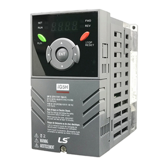
Basic information & precautions 1.2 Product Details Appearance STOP/RESET button Status LED Display RUN button [ENT] button Front cover: Removed when wiring Inverter nameplate Bottom cover: Removed when wiring input power and a motor Inside view after front cover is removed Refer to “1.3 Product assembling &... -
Page 17: Product Assembling & Disassembling
Basic information & precautions 1.3 Product assembling & disassembling To remove the front cover: Press the both indented sides of the cover lightly and pull up. To change the inverter fan: Press the both sides of bottom cover lightly and pull out to your side... -
Page 18: Installation & Wiring
Installation & Wiring 2 Installation & Wiring 2.1 Installation precautions Handle the inverter with care to prevent damage to the plastic components. Do not hold the inverter by the front cover. It may fall off. Install the inverter in a place where it is immune to vibration (5.9 m/s or less). - Page 19 Installation & Wiring Do not install the inverter in any environment where it is exposed to waterdrops, oil mist, dust, etc. Install the inverter in a clean place or inside a “totally enclosed” panel any suspended matter is not entered. ...
-
Page 20: Dimensions
Installation & Wiring 2.2 Dimensions SV004iG5H-2 / SV008iG5H-2 SV015iG5H-2 / SV015iG5H-4 SV004iG5H-4 / SV008iG5H-4... - Page 21 Installation & Wiring SV022iG5H-2 / SV037iG5H-2 / SV040iG5H-2 SV055iG5H-2 / SV075iG5H-2 SV022iG5H-4 / SV037iG5H-4 / SV040iG5H-4 SV055iG5H-4 / SV075iG5H-4 Φ...
- Page 22 Installation & Wiring Φ Inverter [kW] [Kg] [mm] [mm] [mm] [mm] [mm] [mm] [mm] SV004iG5H-2 65.5 0.76 SV008iG5H-2 0.75 65.5 0.77 SV015iG5H-2 95.5 1.12 SV022iG5H-2 120.5 1.84 SV037iG5H-2 120.5 1.89 SV040iG5H-2 120.5 1.89 SV055iG5H-2 3.66 SV075iG5H-2 3.66 SV004iG5H-4 65.5 0.76 SV008iG5H-4 0.75 65.5...
-
Page 23: Terminal Wiring (Control I/O)
Installation & Wiring 2.3 Terminal wiring (Control I/O) - Page 24 Installation & Wiring...
-
Page 25: Specifications For Power Terminal Block Wiring
Installation & Wiring 2.4 Specifications for power terminal block wiring 0.4 - 1.5kW(Three Phase) 2.2 - 4.0kW(Three Phase) T B1 B2 B1 B2 U 5.5 - 7.5kW(Three Phase) B2 U R,S,T Size U,V,W Size Ground Size Terminal Screw Torque Screw Size (Kgf.cm)/lb-in SV004iG5H-2 M3.5... - Page 26 Installation & Wiring Apply the rated torque to terminal screws. Loosen screws can cause of short circuit and malfunction. Tightening the screw too much can damage the terminals and cause short circuit and malfunction. Use copper wires only with 600V, 75℃ ratings for wiring. ...
- Page 27 Installation & Wiring Use the Type 3 grounding method (Ground impedance: Below 100Ω) for 230V class inverters. Use the Special Type 3 grounding method (Ground impedance: Below 10Ω) for 460V class inverters. Use the dedicated ground terminal to ground the inverter. Do not use the screw in the case or chassis, etc for grounding.
-
Page 28: Control Terminal Specification
Installation & Wiring 2.5 Control terminal specification Wire size[mm Terminal Screw Torque Specification Description size [Nm] single Stranded wire Multi-function P1-P4 M2.6 input T/M 1-4 Common M2.6 Terminal power supply Output voltage: 12V for external M2.6 Max output current: 100mA potentiometer Potentiometer:1 - 5kohm Input terminal... - Page 29 Installation & Wiring Note 1) Tie the control wires more than 15cm away from the control terminals. Otherwise, it interferes front cover reinstallation. Note 2) Use Copper wires rated 600V, 75 ℃ and higher. Note 3) Use the recommended tightening torque when securing terminal screws. Note When you use external power supply (24V) for multi-function input terminal (P1-P4), terminals will be active above 12V level.
-
Page 30: Pnp/Npn Selection And Connector For Communication Option
Installation & Wiring 2.6 PNP/NPN selection and connector for communication option 1. When using DC 24V inside inverter [NPN] SW S8 DC 24 V (inside inverter) 2. When using external DC 24V [PNP] SW S8 DC 24 V DC24V (inside inverter) -
Page 31: Terminating Resistor Selection
Installation & Wiring 2.7 Terminating Resistor selection 1. When not using Terminating Resistor SW S9 Communication 2. When using Terminating Resistor SW S9 Communication... -
Page 32: Basic Configuration
Basic configuration 3 Basic configuration 3.1 Connection of peripheral devices to the inverter The following devices are required to operate the inverter. Proper peripheral devices must be selected and correct connections made to ensure proper operation. An incorrectly applied or installed inverter can result in system malfunction or reduction in product life as well as component damage. -
Page 33: Recommended Mccb
Basic configuration 3.2 Recommended MCCB Inverter MCCB ELCB Capacity 004iG5H-2 ABS33c/5, UTE100/15 MC-6a EBS33c/5 008iG5H-2 ABS33c/10, UTE100/15 MC-9a, MC-9b EBS33c/10 015iG5H-2 ABS33c/15, UTE100/15 MC-18a, MC-18b EBS33c/15 022iG5H-2 ABS33c/20, UTE100/20 MC-22b EBS33c/20 037iG5H-2 MC-32a EBS33c/30 ABS33c/30. UTE100/30 040iG5H-2 MC-32a EBS33c/30 055iG5H-2 ABS53c/50, UTE100/50 MC-50a EBS53c/50... -
Page 34: Recommendable Fuse, Reactors
Basic configuration 3.3 Recommendable Fuse, Reactors AC Input fuse [External Fuse] Inverter Capacity AC Reactor DC Reactor Current Voltage 004iG5H-2 10 A 600 V 4.20 mH, 3.5A 008iG5H-2 10 A 600 V 2.13 mH, 5.7A 015iG5H-2 15 A 600 V 1.20 mH, 10A 022iG5H-2 25 A... -
Page 35: Programming Keypad & Basic Operation
Programming Keypad & Basic operation 4 Programming Keypad & Basic operation 4.1 Keypad features Display SET/RUN LED FWD/REV LED 7 Segment LED STOP/RESET Up/Down Left/Right Enter [ENT] Display Lit during forward run Lit during reverse run Blinks when a fault occurs Lit during Operation... -
Page 36: Alpha-Numeric View On The Led Keypad
Programming Keypad & Basic operation Keys Down Used to scroll through codes or decrease parameter value Used to jump to other parameter groups or move a cursor to the left to Left change the parameter value Used to jump to other parameter groups or move cursor to the right to ... -
Page 37: Moving To Other Groups
Programming Keypad & Basic operation 4.3 Moving to other groups There are 5 different parameter groups in SV- iG5H series as shown below. Basic parameters necessary for the inverter to run. Parameters Drive group such as Target frequency, Accel/Decel time settable. Function group 1 Basic function parameters to adjust output frequency and voltage. - Page 38 Programming Keypad & Basic operation Moving to other parameter groups is only available in the first code of each group as the figure shown below. Moving to other groups using the Right Moving to other groups using the Left () () key * Target frequency can be set at 0.0 (the 1st code of drive group).
- Page 39 Programming Keypad & Basic operation How to move to other groups from any codes other than the 1 code Pressing left or right arrow key in any code will return to first code of each group. To move from the F 15 to function group 2 ...
-
Page 40: How To Change The Codes In A Group
Programming Keypad & Basic operation 4.4 How to change the codes in a group Code change in Drive group In the 1 code in Drive group “0.00”, press the Up () key once. The 2 code in Drive group “ACC”... - Page 41 Programming Keypad & Basic operation Navigating codes in a group When moving from F 1 to F 15 in Function group 1 In F 1, continue pressing the Up () key until F15 is displayed. Moving to F15 has been complete.
-
Page 42: Parameter Setting
Programming Keypad & Basic operation 4.5 Parameter setting Changing parameter values in Drive Group When changing ACC time from 5.0 sec to 16.0 sec In the first code “0.00”, press the Up () key once to go to the second code. - Page 43 Programming Keypad & Basic operation Frequency setting When changing run frequency to 30.05 Hz in Drive group In “0.00”, press the Ent () key once. The second decimal 0 becomes active. Press the UP () key until 5 is displayed. ...
- Page 44 Programming Keypad & Basic operation Changing parameter value in Input/Output group When changing the parameter value of F28 from 2 to 5 In F0, press the Ent () key once. Check the present code number. Increase the value to 8 by pressing the Up () key. ...
-
Page 45: Monitoring Of Operation Status
Programming Keypad & Basic operation 4.6 Monitoring of operation status 4.6.1 Output current display Monitoring output current in Drive group In [0.0], continue pressing the Up () or Down () key until [CUr] is displayed. Monitoring output current is provided in this parameter. ... -
Page 46: Fault Display
Programming Keypad & Basic operation 4.6.2 Fault display How to monitor fault condition in Drive group This message appears when an Overcurrent fault occurs. Press the Enter () key or UP/Down key once. The run frequency at the time of fault (30.0) is displayed. ... -
Page 47: Parameter Initialize
Programming Keypad & Basic operation 4.6.3 Parameter initialize How to initialize parameters of all four groups in H93 In H0, press the Enter () key once. Code number of H0 is displayed. Increase the value to 3 by pressing the Up () key. ... -
Page 48: Frequency Setting And Basic Operation
Programming Keypad & Basic operation 4.7 Frequency Setting and Basic Operation The following instructions are given based on the fact that all parameters are set to factory defaults. Results could be different if parameter values are changed. In this case, initialize parameter values (see page 139) back to factory defaults and follow the instructions below. -
Page 49: Frequency Setting Via Potentiometer & Operating Via Terminals
Programming Keypad & Basic operation 4.7.2 Frequency Setting via potentiometer & operating via terminals Apply AC input power to the inverter. When 0.00 appears Press the Up () key four times. Frq is displayed. Frequency setting mode is selectable. ... -
Page 50: Frequency Setting Via Potentiometer & Operating Via The Run Key
Programming Keypad & Basic operation 4.7.3 Frequency setting via potentiometer & operating via the Run key Apply AC input power to the inverter. When 0.00 is displayed, press the Up () key three times. “drv” is displayed. Operating method is selectable. ... - Page 51 Programming Keypad & Basic operation Wiring Operating pattern...
-
Page 52: Function List
Function list 5 Function list 5.1 Drive Group Address Min/ Adj. Parameter Factory Description during Page display communi- name defaults range cation This parameter sets the frequency that the inverter is commanded to output. During Stop: Frequency Command [Frequency 0.00 A100 During Run: Output Frequency 0.00... - Page 53 Function list Address Min/ Adj. Parameter Factory Description during Page display communi- name defaults range cation A109 [Motor RPM] Displays the number of Motor RPM. [Inverter DC Displays DC link voltage inside the A10A link voltage] inverter. This parameter displays the item selected at H73- [Monitoring item select].
-
Page 54: Function Group 1
Function list 5.2 Function group 1 Address Min/ Adj. Parameter Factory Description during Page display communi- name defaults range cation A200 [Jump code] 0 - 99 Sets the parameter code number to jump. 1 0 Fwd and rev run enable [Forward/ A201 Reverse run... - Page 55 Function list Function group 1 Address Min/ Adj. Parameter Factory Description during Page display communi- name defaults range cation This parameter sets the highest frequency the inverter can output. It is frequency reference for Accel/Decel 40 - (See H70) [Max A215 50.00 frequency]...
- Page 56 Function list Function group 1 Address Min/ Adj. Parameter Factory Description during Page display communi- name defaults range cation 0 Linear 1 Square A21E [V/F pattern] 0 - 4 2 User V/F 3 High Torque 1 4 High Torque 2 [User V/F A21F 12.50...
- Page 57 Function list Function group 1 Address Min/ Adj. Parameter Factory Description during Page display communi- name defaults range cation This parameter sets max current capable of flowing to the motor continuously for 1 [Electronic 50 - minute. The set value is the percentage of H33 – A233 thermal level for 1 minute]...
- Page 58 Function list Function group 1 Address Min/ Adj. Parameter Factory Description during Page display communi- name defaults range cation This parameter stops accelerating during acceleration, decelerating during constant speed run and stops decelerating during deceleration. During During During Decel constant run Accel Bit 2 Bit 1...
- Page 59 Function list Function group 1 Address Min/ Adj. Parameter Factory Description during Page display communi- name defaults range cation In case of choosing F65 as a 1 or 2, it [Up-down step 0-400 A242 means increase or decrease of 0.00 frequency] [Hz] frequency according to up-down input...
-
Page 60: Function Group 2
Function list 5.3 Function group 2 Address Min/ Adj. Parameter Factory Description during Page display communi- name defaults range cation A300 [Jump code] 0-95 Sets the code number to jump. A301 [Fault history 1] - Stores information on the types of faults, A302 [Fault history 2] - the frequency, the current and the... - Page 61 Function list Function group 2 Address Min/ Adj. Parameter Factory Description during Page display communi- name defaults range cation [S-Curve Set the speed reference value to form a 1-100 A311 accel/decel curve at the start during accel/decel. If it is start side] set higher, linear zone gets smaller.
- Page 62 Function list Function group 2 Address Min/ Adj. Parameter Factory Description during Page display communi- name defaults range cation H20- Restart Operation Normal [Power after after fault accel instant start] power failure Bit 3 Bit 2 Bit 1 Bit 0 ...
- Page 63 Function list Function group 2 Address Min/ Adj. Parameter Factory Description during Page display communi- name defaults range cation [Auto Restart 0-60 This parameter sets the time between A31B time] [sec] restart tries. 0.2kW [Motor type 0.2- A31E select] 22.0 22.0 22.0kW [Number of...
- Page 64 Function list Function group 2 Address Min/ Adj. Parameter Factory Description during Page display communi- name defaults range cation This parameter affects the audible sound of the motor, noise emission from the [Carrier inverter, inverter temp, and leakage 1 - 15 A327 frequency current.
- Page 65 Function list Function group 2 Address Min/ Adj. Parameter Factory Description during Page display communi- name defaults range cation Terminal I input (0 - 20 mA) [PID F/B A332 0 - 2 Terminal V1 input (0 - 10 V) select] RS-485 communication feedback A333 [P gain for PID]...
- Page 66 Function list Function group 2 Address Min/ Adj. Parameter Factory Description during Page display communi- name defaults range cation [Frequency Based on Max freq (F21) A346 Reference for 0 - 1 Based on Delta freq. Accel/Decel] Settable unit: 0.01 second. [Accel/Decel A347 0 - 2...
- Page 67 Function list Function group 2 Address Min/ Adj. Parameter Factory Description during Page display communi- name defaults range cation Always ON Keeps ON when its temp is higher than inverter protection limit temp. Activated only during operation when [Cooling fan A34D 0 - 2 its temp is below that of inverter...
- Page 68 Function list Function group 2 Address Min/ Adj. Parameter Factory Description during Page display communi- name defaults range cation [Parameter Copy the parameters from inverter and A35B 0 - 1 read] save them into remote loader. [Parameter Copy the parameters from remote loader A35C 0 - 1 write]...
-
Page 69: Input/Output Group
Function list 5.4 Input/output group Address Min/ Adj. Parameter Factory Description during Page display communi- name defaults range cation A400 [Jump code] 0 - 87 Sets the code number to jump. [NV input Min 0 - -10 Sets the minimum voltage of the NV (- A402 0.00 voltage]... - Page 70 Function list Address Min/ Adj. Parameter Factory Description during Page display communi- name defaults range cation Emergency Stop Trip [Multi-function A412 input terminal P2 define] Reset when a fault occurs {RST} [Multi-function Jog operation command A413 input terminal Multi-Step freq – Low P3 define] Multi-Step freq –...
- Page 71 Function list Input/output group Address Min/ Adj. Parameter Factory Description during Page display communi- name default range cation BIT3 BIT2 BIT1 BIT0 [Input terminal A419 status display] [Output BIT1 BIT0 A41A terminal status Relay2 Relay1 display] [Filtering time If the value is set higher, the constant for A41B 1 - 15...
- Page 72 Function list Address Min/ Adj. Parameter Factory Description during Page display communi- name default range cation Output current 150 % Output AC 282V AC 564V voltage Inverter DC DC 400V DC 800V link voltage [Analog output A433 level Based on 10V. adjustment] [Frequency A434...
- Page 73 Bit 1 Bit 0 terminal select A439 when 0 - 3 communication error occurs] Set communication protocol. [Communicatio A43B n protocol 0 - 1 Modbus RTU select] LS BUS [Inverter A43C Set for RS485 communication number]...
- Page 74 Function list Input/Output Group Address Min/ Adj. Parameter Factory Description during Page display communi- name defaults range cation Select the Baud rate of the RS485. 1200 [bps] 2400 [bps] A43D [Baud rate] 0 - 4 4800 [bps] 9600 [bps] 19200 [bps] It is used when freq command is given via V1 /I terminal or RS485.
- Page 75 Function list Input/Output Group Address Min/ Adj. Parameter Factory Description during Page display communi- name defaults range cation [Read address A442 register 1] [Read address A443 register 2] [Read address A444 register 3] [Read address A445 The user can register up to 8 register 4] discontinuous addresses and read them [Read address...
- Page 76 Function list Input/Output Group Address Min/ Adj. Parameter Factory Description Page during communi- name defaults display range cation [Write address A44D register 4] [Write address A44E register 5] [Write address A44F register 6] [Write address A450 register 7] [Write address A451 register 8] If I62 is set “3”, when the drive go into the...
-
Page 77: Application Group
Function list 5.5 Application Group Address Min/ Adj. Parameter Factory Description during Page display communi- name defaults range cation [Sleep delay A501 2000 Sets a sleep delay time in PID drive. 20.0 time] Sets a sleep frequency when executing a [Sleep sleep function in PID control drive. - Page 78 Function list Application Group Address Min/ Adj. Parameter Factory Description during Page display communi- name defaults range cation The auxiliary motors turns on or off after 0.1- [Aux Stop 600.0 A512 the auxiliary motor stop delay time Delay Time] elapses. When the auxiliary motor stops, the main motor accelerates up to the auxiliary motor 600.0...
- Page 79 Function list Application Group Address Min/ Adj. Parameter Factory Description during Page display communi- name defaults range cation [Start Ramp A523 6000.0 Multi-step acceleration time 10.0 Acc] [End Ramp A524 6000.0 Multi-step deceleration time 10.0 Dec] [Start & End 0-400 A525 Acc/Dec time switch frequency 0.00...
- Page 80 Function list Application Group Address Min/ Adj. Parameter Factory Description during Page display communi- name defaults range cation NONE [Broken Belt A536 Warning Select] Free-Run 15.0- [Broken Belt A537 Broken Belt Freq 15.0 Freq] [Hz] [Current A538 Current Torque display. Torque] [Broken Belt A539...
-
Page 81: Control Block Diagram
Control Block Diagram 6 Control Block Diagram... -
Page 82: Frequency Setting
Control Block Diagram 6.1 Frequency setting... - Page 83 Control Block Diagram...
-
Page 84: Drive Command Setting
Control Block Diagram 6.2 Drive command setting... -
Page 85: Accel/Decel Setting And V/F Control
Control Block Diagram 6.3 Accel/Decel setting and V/F control... -
Page 86: Basic Functions
Basic Functions 7 Basic Functions 7.1 Frequency mode Keypad Frequency setting 1 7.1.1 Group Code Parameter Name Setting Range Default Unit 0.00 [Frequency Command] 0 - 400 0.00 Drive group [Frequency mode] 0 - 8 Set Frq – [Frequency mode] to 0 {Frequency setting via Keypad 1}. ... -
Page 87: Frequency Setting Via -10 - +10[V] Input
Basic Functions Frequency setting via –10 - +10[V] input 7.1.3 Group Code Parameter Name Setting Range Default Unit 0.00 [Frequency Command] 0 -400 0.00 Drive group [Frequency Mode] 0 - 8 [NV input minimum voltage] 0 - -10 [Frequency corresponding to 0 - 400 0.00 I/O group... -
Page 88: Frequency Setting Via 0 - 10 [V] Input Or Terminal Potentiometer
Basic Functions ► I6 - I10: Setting input range and corresponding frequency to 0 - +10V V1 input voltage Ex) when minimum (+) input voltage is 2V with corresponding frequency 10Hz and Max voltage is 8V with run freq. 7.1.4 Frequency setting via 0 - 10 [V] input or Terminal Potentiometer Group... -
Page 89: Frequency Setting Via 0 - 20 [Ma] Input
Basic Functions ► Wire the terminals as shown below and refer to I 6 - I 10. 7.1.5 Frequency setting via 0 - 20 [mA] input Group Code Parameter Name Setting Range Default Unit 0.00 [Frequency Command] 0 -400 0.00 Drive group [Frequency Mode]... -
Page 90: Frequency Setting Via 0 - 10[V] + 0 - 20[Ma] Input
Basic Functions Group Code Parameter Name Setting Unit [NV input Min voltage] [Frequency corresponding to I 2] 0.00 [NV input Max voltage] 10.00 [Frequency corresponding to I 4] 5.00 [V1 input Min voltage] 0.00 [Frequency corresponding to I 7] 0.00 I/O group [V1 input max voltage] 10.00... -
Page 91: Frequency Setting Via Digital Volume (Up-Down)
Basic Functions 7.1.9 Frequency setting via Digital Volume (up-down) Group Code Parameter Name Setting Range Default Unit [Frequency Command] 0 -400 0.00 Drive group [Frequency Mode] 0 - 8 Select 7 in Frq code of Drive group. Related code: I 59, I 60, I 61 ... -
Page 92: Multi-Step Frequency Setting
Basic Functions 7.2 Multi-Step Frequency setting Group Code Parameter Name Setting Range Default Unit [Frequency Command] 0 - 400 0.00 [Frequency Mode] 0 - 8 Drive group [Multi-Step frequency 1] 10.00 [Multi-Step frequency 2] 0 - 400 20.00 [Multi-Step frequency 3] 30.00 [Multi-function input terminal P2 define]... -
Page 93: Operating Command Setting Method
Basic Functions 7.3 Operating command setting method 7.3.1 Operation via keypad RUN key and STOP/RST key Group Code Parameter Name Setting Range Default Unit [Drive mode] 0 - 4 Drive group [Direction of motor rotation F, r select] Set drv – [Drive mode] to 0. ... -
Page 94: Operating Command Via Fx, Rx Terminal 2
Basic Functions 7.3.3 Operating command via FX, RX terminal 2 Group Code Parameter Name Setting Range Default Unit Drive group [Drive mode] 0 - 4 [Multi-function input 0 - 30 terminal P1 define] I/O group [Multi-function input 0 - 30 terminal P2 define] ... -
Page 95: Rotating Direction Select Via -10 - +10[V] Input Of V1 Terminal
Basic Functions Rotating direction select via –10 - +10[V] input of V1 7.3.5 terminal Group Code Parameter Name Setting Range Default Unit Drive group [Frequency setting] 0 - 8 [Drive mode] 0 - 4 Set frq to 2. Inverter is operating as the table below regardless of Drive mode setting. -
Page 96: Power On Start Select
Basic Functions 7.3.7 Power On Start select Group Code Parameter Name Setting Range Default Unit Drive group [Drive mode] 1, 2 0 - 3 Function [Power On Start select] 0 - 1 group 2 Set H20 to 1. When AC input power is applied to the inverter with drv set to 1 or 2 {Run via control terminal} ON, motor starts acceleration. -
Page 97: Accel/Decel Time And Pattern Setting
Basic Functions 7.4 Accel/Decel time and pattern setting 7.4.1 Accel/Decel time setting based on Max frequency Group Code Parameter Name Setting Range Default Unit [Accel time] 0 - 6000 Drive group [Decel time] 0 - 6000 10.0 Function [Max Frequency] 40 - 400 60.00 group 1... -
Page 98: Accel/Decel Time Setting Based On Operating Frequency
Basic Functions ► More precise time unit can be set corresponding to load characteristics as shown below. ► In SV-iG5H, number display is available up to 5. Therefore, if time unit is set to 0.01 sec, Max Accel/Decel time would be 600.00 sec. Group Code Parameter Name... -
Page 99: Multi-Accel/Decel Time Setting Via Multi-Function Terminals
Basic Functions 7.4.3 Multi-Accel/Decel time setting via Multi-function terminals Group Code Parameter Name Setting Range Default Unit [Accel time] 0 - 6000 5.0 Drive group [Decel time] 0 - 6000 10.0 [Multi-function input terminal P1 define] [Multi-function input terminal P2 0 - 30 define] [Multi-function input terminal P3... -
Page 100: Accel/Decel Pattern Setting
Basic Functions 7.4.4 Accel/Decel pattern setting Group Code Parameter Name Setting Range Default Unit [Accel pattern] Linear Function group 1 [Decel pattern] S-curve [S-Curve Accel/Decel start side] Function group 2 [S-Curve Accel/Decel end side] Accel/Decel pattern is settable at F2 and F3. ... -
Page 101: Accel/Decel Disable
Basic Functions ► Note that setting Frequency Ref. for Accel/decel (H70) is set to Max Freq and target freq is set below Max freq. the shape of S-curve may be distorted. If Target Frequency is below Max Frequency, the waveform will be shown with the top portion cut out. -
Page 102: V/F Control
Basic Functions 7.5 V/F control 7.5.1 Linear V/F pattern operation Group Code Parameter Name Setting Range Default Unit [Base frequency] 30 - 400 60.00 Function group 1 [Start frequency] 0.1 - 10.0 0.50 [V/F pattern] 0 - 4 Function group 2 H40 [Control mode select] 0 - 2 ... -
Page 103: High Starting Torque Pattern
Basic Functions 7.5.3 High starting torque pattern Group Code Parameter Name Setting Range Default Unit Function group 1 [V/F pattern] 3, 4 0 - 4 Set F30 to {3 High starting torque 1} or {4 High starting torque 2}. ... -
Page 104: Output Voltage Adjustment
Basic Functions 7.5.5 Output voltage adjustment Group Code Parameter Name Setting Range Default Unit [Output voltage Function group 1 F39 40 - 110 adjustment] This function is used to adjust the output voltage of the inverter. This is useful when you use a motor that has a rated voltage lower than the input voltage. -
Page 105: Auto Torque Boost
Basic Functions If the boost value is set much higher than required, it may cause motor overheating due to over- energizing. 7.5.7 Auto torque boost Group Code Parameter Name Setting Range Default Unit Function group 1 F27 [Torque Boost select] 0 - 1 [No load motor Current] 0.1 - 100 -... -
Page 106: Stop Method Select
Basic Functions 7.6 Stop method select 7.6.1 Decel to stop Group Code Parameter Name Setting Range Default Unit Function group 1 [Stop mode select] 0 - 3 Select 0 {decel to stop} in F4 code. Motor decelerates to 0 Hz and stops during the setting time. 7.6.2 DC braking to stop Group... -
Page 107: Frequency Limit
Basic Functions 7.7 Frequency limit 7.7.1 Frequency limit using Max Frequency and Start Frequency Group Code Parameter Name Setting Range Default Unit [Max frequency] 40 - 400 50.00 Function group 1 [Start frequency] 0.1 - 10 0.50 Max Frequency: Frequency highest limit. Any frequency cannot be set above [Max frequency] except for F22 [Base frequency]. -
Page 108: Skip Frequency
Basic Functions 7.7.3 Skip frequency Group Code Parameter Name Setting Range Default Unit [Skip frequency select] 0 - 1 [Skip frequency low limit 1] - 0.1 - 400 10.00 Hz Function group 2 [Skip frequency low limit 3] - 0.1 - 400 35.00 Hz ... -
Page 109: Advanced Functions
Advanced functions 8 Advanced functions 8.1 DC brake Stopping motor by DC brake 8.1.1 Group Code Parameter Name Setting Range Default Unit Function [Stop mode select] 0 - 3 group 1 [DC Brake start frequency] 0.1 - 60 5.00 [DC Brake wait time] 0 - 60 [DC Brake voltage] 0 - 200... -
Page 110: Starting Dc Brake
Advanced functions ► In case of DC brake at high load inertia and frequency, change the DC brake controller gain according to H37 set value. Less than 10 times motor inertia Load inertia ratio 10 times motor inertia Greater than 10 times motor inertia 8.1.2 Starting DC brake Group... -
Page 111: Dc Brake At A Stop
Advanced functions 8.1.3 DC brake at a stop Group Code Parameter Name Setting Range Default Unit Function [DC Brake start voltage] 0 - 200 group 1 [Multi-function Input I/O group terminal P3 Function 0 - 25 select] F12: It sets the level as a percent of H33 – [Motor rated current]. ... -
Page 112: Jog Operation
Advanced functions 8.2 Jog operation 8.2.1 Terminal jog operation Group Code Parameter Name Setting Range Default Unit Function [Jog frequency] 0 - 400 10.00 group 1 [Multi-function input terminal I/O group I21 0 - 30 P4 define] Set the desired jog frequency in F20. ... -
Page 113: Terminal Jog Fx/Rx Operation
Advanced functions 8.2.2 Terminal JOG FX/RX operation Group Code Parameter Name Setting Range Default Unit Function [Jog frequency] 0 - 400 10.00 group 1 [Multi-function input terminal 0 - 30 P3 define] I/O group [Multi-function input terminal 0 - 30 P4 define] ... -
Page 114: Up-Down Operation
Advanced functions 8.3 UP-DOWN Operation 8.3.1 Up-down storage function Group Code Parameter Name Setting Range Default Unit Drive [Frequency setting method] group [Multi-function input terminal P1 define] [Multi-function input terminal P2 define] 0 - 30 I/O group [Multi-function input terminal P3define] [Multi-function input terminal P4define]... -
Page 115: Up-Down Mode Select
Advanced functions 8.3.2 Up-down mode select Group Code Parameter Name Setting Range Default Unit Drive [Frequency setting method] group [Multi-function input terminal P1 define] [Multi-function input terminal 0 - 30 I/O group P3define] [Multi-function input terminal P4define] [Up-down mode select] Function group 1 [Up-down step frequency]... - Page 116 Advanced functions ► When F65 is 1: It is increased as many as step frequency set as F66 at the rising edge of multi-function input set as UP and when up-down is defined, it saves frequency at the falling edge. It is decreased as many as step frequency set as F66 at the falling edge of rising edge of multi-function input set as DOWN and when up-down is defined, it saves frequency as the falling edge.
-
Page 117: 3-Wire
Advanced functions 8.4 3-Wire Group Code Parameter Name Setting Range Default Unit [Multi-function Input terminal P1 select] I/O group 0 - 30 [Multi-function Input terminal P4 select] Select the terminal from P1-P4 for use as 3-Wire operation. If P4 is selected, set I20 to 17 {3-Wire operation}. ... -
Page 118: Dwell Operation
Advanced functions 8.5 Dwell operation Group Code Parameter Name Setting Range Default Unit [Dwell frequency] 0.1 - 400 5.00 Function group 2 [Dwell time] 0 - 10 In this setting, motor begins to accelerate after dwell operation is executed for dwell time at the dwell frequency. - Page 119 Advanced functions ► H30: Set the motor type connected to the inverter output side. 0.2kW [Motor type select] 22.0 22.0kW ► H31: Enter the pole number on the Motor nameplate. ► H32: Enter the slip frequency in accordance with the following formula and motor nameplate.
-
Page 120: Pid Control
Advanced functions 8.7 PID control Group Code Parameter Name Setting Range Default Unit [PID Operation select] 0 - 1 [PID Feedback select] 0 - 1 [P gain for PID controller] 0 - 999.9 300.0 [Integral time for PID controller 0.1- 32.0 (I gain)] Function [Differential time for PID... -
Page 121: Pid Control Diagram
Advanced functions value may reduce the nominal error. If the value is reduced, response will be faster but setting too low may lead to controller oscillation. ► H53: Set the output value to the variation of the error. The error is detected by 0.01 sec in SV-iG5H. - Page 122 Advanced functions 1) Adds RS-485 communications to PID Feedback category. 2) PID REF value can be changed and checked in the “rEF” of the DRV group. Unit is [Hz] when H58=0 and [%] when H58=1 3) PID FBK value cab be checked in the “Fbk” of the DRV group Unit is sane with the “rEF”...
-
Page 123: Sleep & Wake-Up
Advanced functions 8.7.2 Sleep & Wake-up In the night for example, if output frequency of PID control is maintained over sleep delay time(A1) due to not enough flux, Sleep function becomes sleep mode automatically and inverter is stop. Under sleep mode, if error of PID Reference and Feedback is over A6(Wake-up Level), Sleep mode is released and the inverter restarts. -
Page 124: Pre-Pid
Advanced functions When the inverter is entering sleep mode, the PID reference is increased by A03_Sleep Boost Set value for the time defined by parameter A04_Sleep Boost time. 8.7.4 Pre-PID Using Pre-PID, the inverter ramps up to A7_Pre-PID Mode Freq. without PID control via ACC time. -
Page 125: Multi Step Pid
Advanced functions Pre-PID Timer and Exit Level operates as a OR condition (where if either condition is met, the PID controller is turned on) Group Code Parameter Name Setting Range Default Unit Pre-PID Mode Freq 0-Max Freq 0.00 Application Pre-PID Exit Level 0.0-100.0 20.0... -
Page 126: Mmc
Advanced functions 8.9 MMC The MMC (Multiple Motor Control) function is used to control multiple motors for in a pump system. The main motor connected with the inverter output, operated by the PID controller. The auxiliary motors are connected with the supply power and turned on and off by the relay within the inverter. - Page 127 Advanced functions ► A11: Selects the MMC operation settings. ► A12: Decides the number of auxiliary motors to use. ► A13, A14: Sets the auxiliary motor start frequency. ► A15, A16: Sets the auxiliary motor stop frequency. ► A17, A18: The auxiliary motors turns on or off after the auxiliary motor stop delay time elapses.
-
Page 128: Mmc(Auto Change)
Advanced functions [Aux All Stop] Note When run signal is off or the inverter has gone into sleep mode on either FIFO/FILO, the motor set at A26 [start motor] always starts. 8.10 MMC(Auto Change) Auto Change function is automatic rotation of the start order between auxiliary motors. Prolonged continuous operation of a motor deteriorates motor capabilities. - Page 129 Advanced functions Auto Change is activated when auxiliary motors are in the operating state over time of A24 and then every auxiliary motor is stopped and the inverter operation frequency is below the frequency set at A25. Note Start order and stop order of the auxiliary motors are based on the order set at A22(FIFO/FILO).
-
Page 130: Motor Alternation
Advanced functions 8.11 Motor Alternation It is a function that can extend the life of the motor through M/C alternation sequence. In many industrial pumping applications, two identical pumps are used for the same job. A standby unit is available in case the first pump fails. However, the main motor pump might deteriorate and provide no safety margin. -
Page 131: Relay On/Off Delay
Advanced functions 8.12 Relay On/Off Delay Delay time setting to activate or deactivate relay-1(A1, B1, C1), relay-2(A2, C2) outputs. If the input terminal‘s state is not changed during the set time, when the terminal receives an input, it is recognized as On or Off. Group Code Parameter Name Setting... -
Page 132: Relay On/Off Control
Advanced functions 8.13 Relay On/Off Control If the analog input value is over the set value, the output relay or multi-function output terminal can be turned ON or OFF. Select the analog input to use for ON/OFF control at F72 and set the levels at which the output terminal is ON and OFF at F73, 74 respectively. If the analog input value is over the value set at F73, the output terminal is ON and if below F74, it is OFF. -
Page 133: Regeneration Avoidance Function
Advanced functions 8.15 Regeneration Avoidance Function The regenerative status can be avoided by detecting the DC Link Voltage level and raising the frequency to burn out the excessive regenerative energy. Regenerative energy is occasionally generated due to other fan devices connected in the same duct. -
Page 134: Auto-Tuning
Advanced functions 8.16 Auto-tuning Group Code Parameter Name Setting Range Default Unit [Auto tuning] 0 - 1 Function [Stator resistance (Rs)] 0 - 28 group 2 [Leakage inductance (L)] 0 - 300.00 Automatic measuring of the motor parameters is provided. ... -
Page 135: Factory Default By Motor Ratings
Advanced functions 8.17 Factory default by motor ratings Stator Current No-load Rated slip Leakage Input Motor rating resistance rating current freq inductance voltage [kW] [Hz] [mH] [] 2.33 14.0 122.00 3.00 6.70 61.00 0.75 2.33 2.46 28.14 2.33 1.13 14.75 2.00 0.869 11.31... -
Page 136: Energy-Saving Operation
Advanced functions 8.18 Energy-saving operation Group Code Parameter Name Setting Range Default Unit Function [Energy-saving operation] - 0 - 30 group 1 Set the amount of output voltage to be reduced in F40. Set as the percent of Max output voltage. ... - Page 137 Advanced functions The following table shows 4 types of Speed search selection. Speed search during Speed search during Speed search during Speed search H20 – [Power ON Instant Power H21- [Restart after during start] Failure restart fault reset] Acceleration Bit 3 Bit 2 Bit 1 Bit 0...
- Page 138 Advanced functions ► EX) Speed search during Instant Power Failure restart When the input power is cut off due to instant power failure, the inverter outputs Low voltage trip (LV) to hold the output. When the power is restored, the inverter outputs the frequency before the low voltage trip and the voltage is increased due to PI control.
-
Page 139: Auto Restart Try
Advanced functions 8.20 Auto restart try Group Code Parameter Name Setting Range Default Unit [Number of Auto Restart try] 0 - 10 Function group 2 [Auto Restart time] 0 - 60 This parameter sets the number of times auto restart is activated in H26. ... - Page 140 Advanced functions ► The following pattern is shown when the H26 – [Number of auto restart try] is set to 2.
-
Page 141: Operating Sound Select (Carrier Frequency Change)
Advanced functions 8.21 Operating sound select (Carrier frequency change) Group Code Parameter Name Setting Range Default Unit Function [Carrier frequency] 1 - 15 group 2 This parameter affects the sound of the inverter during operation. Motor sound reduced Inverter heat loss increased H39 When setting carrier frequency high, Inverter noise increased Inverter leakage current increased... -
Page 142: Frequency Setting And
Advanced functions ► Used when an inverter operates 2 motors connected to two different types of the loads. ► 2 motor operation does not drive 2 motors at the same time. ► As the figure below, when using two motors with an inverter by exchanging them, select one motor from 2 motors connected. - Page 143 Advanced functions ► Selects the self drive in the 2 switching of drv2 among the followings Operation via Run/Stop key on the Keypad FX: Forward Run command Terminal RX: Reverse Run command drv2 Drive mode 2 operation FX: Run/Stop command RX: Forward/Reverse command Operation via communication ►...
- Page 144 Advanced functions ► The following figure is drawn when setting is like the above and command frequency is 30 [Hz], F4 [stop method]=0 ① Accelerate for accel time up to setting frequency by Drive 1 mode, FX signal. ② Drive continuously under FX is ON because DRV2 is 1 when P4 terminal input is ON and change into 2 ③...
-
Page 145: Stall Prevention And Power Braking
Advanced functions 8.24 Stall Prevention and Power Braking Group Code Parameter Name Setting Range Default Unit Select stop method 0 - 3 BIT 0: stall prevention under Accel BIT 1: stall prevention Function F 59 0 - 7 under constant speed group 1 BIT 2: stall prevention under Decel... -
Page 146: Draw Operation
Advanced functions 8.25 DRAW Operation Group Code Parameter Name Setting Range Default Unit DRAW mode select - 0 - 3 Function Group 1 DRAW ratio 0.0 - 100.0 ► It’s a kind of open loop tension control that uses the speed difference of motor running under main frequency command to keep material’s tension in between steady. - Page 147 Advanced functions ► DRAW operation example If draw operation is set to 30Hz, F70=3(V1: -10V -10V), F71=10.0% selected, (I3-I15 = plant shipment) Frequency that gets changed by DRAW operation is 27Hz(V1=-10V) - 33Hz(V1=10V) When operating DRAW, set command frequency to FRQ/FRQ2 and set the rest of it from F70(DRAW mode select).
-
Page 148: Phase Pwm Operation
Advanced functions 8.26 2 Phase PWM Operation Group Code Parameter Name Setting Range Default Unit PWM controlling mode Function Group 2 H48 0: NORMAL PWM 0 - 2 1: 2 phase PWM ► Heat loss and leakage current from inverter can be reduced when H48 is set to 1(2 phase PWM) according to the ratio of load. -
Page 149: Operating Mode Select When Cooling Fan Trip Occurs
Advanced functions 8.28 Operating mode select when cooling fan trip occurs Group Code Parameter Name Setting Range Default Unit Function [Operating mode when 0 - 1 group 2 cooling fan trip occurs] [Multi-function relay1 select] 18 0 - 27 I/O group [Multi-function relay2 select] 18 0 - 27 ... -
Page 150: Accel/Decel Change Frequency
Advanced functions 8.29 Accel/Decel Change Frequency This function is to use a different ACC/DEC time starting from a set frequency. At start, up to A37_Start&End Ramp frequency, the motor accelerates a normal time and from A37 frequency, ACC time references A35_StartRampAcc. ... -
Page 151: Fire Mode
Advanced functions 8.30 Fire Mode Fire mode is used in case of an emergency to operate the inverter to extract smoke outdoors in traffic tunnels, subway stations, stairwells, etc When Fire mode is activated the inverter ignores all internal faults and motor protecting features to keep the motor running. -
Page 152: Parameter Read/Write
Advanced functions 8.31 Parameter read/write Group Code Parameter Name Setting Range Default Unit [Parameter read] 0 - 1 Function group 2 [Parameter write] 0 - 1 Used to read/write Inverter Parameters using remote keypad. Take caution when Parameter write (H92) is executed. By doing this, parameters in inverter are cleared and parameters in remote keypad are copied to inverter. -
Page 153: Parameter Initialize / Lock
Advanced functions 8.32 Parameter Initialize / Lock 8.32.1 Parameter initialize Group Code Parameter Name Setting Range Default Unit [Parameter initialize] 5 groups initialize Drive group initialize F 1 group Function initialize group 2 F 2 group initialize I/O group initialize Application group initialize... - Page 154 Advanced functions ► Follow the steps below when you register the password for the first time. Step Note Keypad display Move to H94 code. Press Enter () key twice. Register password. (Ex: 123) 123 will blink when Enter () key is pressed. Press Enter () key.
-
Page 155: Monitoring
Monitoring 9 Monitoring 9.1 Operating status monitoring Output current 9.1.1 Group Code Parameter Name Setting Range Default Unit Drive group [Output current] Inverter output current can be monitored in Cur. 9.1.2 Motor RPM Group Code Parameter Name Setting Range Default Unit Drive group... -
Page 156: Inverter Dc Link Voltage
Monitoring 9.1.3 Inverter DC Link Voltage Group Code Parameter Name Setting Range Default Unit Drive group [Inverter DC Link Voltage] Inverter DC link voltage can be monitored in dCL. ► times the value of input voltage is displayed while motor is at a stop. 9.1.4 User display select Group... -
Page 157: Monitoring The I/O Terminal
Monitoring Group Code Parameter Name Setting Range Default Unit Drive mode (drv) Frequency mode (Frq) Multi-step frequency 1(St1) Multi-step frequency 2(St2) Multi-step frequency 3(St3) Output current (CUr) Motor rpm (rPM) Inverter DC link voltage (dCL) User display select (vOL) Fault display 1(nOn) Operating direction select (drC) Output current 2... -
Page 158: Output Terminal Status Monitoring
Monitoring ► The following is displayed when P1, P3, P4 are ON and P2 are OFF. 9.2.2 Output terminal status monitoring Group Code Parameter Name Setting Range Default Unit [Output terminals I/O group status display] Current output terminals (relays) status (ON/Off) can be monitored in I26. ►... -
Page 159: Monitoring Fault Condition
Monitoring 9.3 Monitoring fault condition 9.3.1 Monitoring current fault status Group Code Parameter Name Setting Range Default Unit Drive group [Current Fault Display] Fault occurred during operation is displayed in nOn. Up to 3 kinds of faults can be monitored. ►... -
Page 160: Fault History Monitoring
Monitoring 9.3.2 Fault History Monitoring Group Code Parameter Name Setting Range Default Unit [Fault history 1] Function group 2 [Fault history 5] [Reset fault history] 0 - 1 H 1 - H 5: Up to 5 faults information is stored. ... -
Page 161: Analog Output
Monitoring 9.4 Analog Output Group Code Parameter Name Setting Range Default Unit [Analog output item select] 0 - 3 I/O group [Analog output level adjustment] 10 - 200 Output item and the level from the AM terminal are selectable and adjustable ►... -
Page 162: Multi-Function Output Terminal Relay 1 And Relay 2
Monitoring 9.5 Multi-function output terminal Relay 1 and Relay 2 Group Code Parameter Name Setting Range Default Unit FDT-1 [Multi-function relay1 select] FDT-2 FDT-3 [Multi-function relay2 select] FDT-4 FDT-5 Overload {OLt} Inverter Overload {IOLt} Motor stall {STALL} Over voltage trip {OV} Low voltage trip {LV} 10 Inverter overheat {OH} 11 Command loss... - Page 163 Monitoring Group Code Parameter Name Setting Range Default Unit Select the desired item to be output via relays. ► I56: When 17 {Fault display} is selected in I54 and I55, Multi-function output relays will be activated with the value in I56.
- Page 164 Monitoring 1: FDT-2 ► Activated when the preset frequency matches frequency detection level (I52) and FDT- 1 condition is met. ► Active condition: (Preset frequency = FDT level) & FDT-1 Group Code Parameter Name Setting Range Default Unit [Detected Frequency level] 30.00 I/O group 0 - 400...
- Page 165 Monitoring 2: FDT-3 ► Activated when run frequency meets the following condition. ► Active condition: Absolute value (FDT level - run frequency) <= FDT Bandwidth/2 Group Code Parameter Name Setting Range Default Unit [Detected Frequency 30.00 level] I/O group 0 - 400 [Detected Frequency 10.00 Bandwidth]...
- Page 166 Monitoring 3: FDT-4 ► Activated when run frequency meets the following condition. Active condition: Accel time: Run Frequency >= FDT Level Decel time: Run Frequency > (FDT Level – FDT Bandwidth/2) Group Code Parameter Name Setting Range Default Unit [Detected Frequency 30.00 level] I/O group...
- Page 167 Monitoring 4: FDT-5 ► Activated as B contact contrast to FDT-4. Active condition: Accel time: Run Frequency >= FDT Level Decel time: Run Frequency > (FDT Level – FDT Bandwidth/2) Group Code Parameter Name Setting Range Default Unit [Detected Frequency 30.00 level] I/O group...
- Page 168 Monitoring 8: Over voltage trip (Ovt) ► Activated when over voltage trip occurs due to DC link voltage exceeded 400Vdc for 200V class and 820Vdc for 400V class. 9: Low voltage trip (Lvt) ► Activated when low voltage trip occurs due to DC link voltage under 180Vdc for 200V class and 360Vdc for 400V class.
- Page 169 Monitoring 13: During stop ► Activated during stop without active command. 14: during constant run ► Activated during constant speed operation. 15: During speed searching ► Refer to page 122. 16: Wait time for run signal input ► This function becomes active during normal operation and that the inverter waits for active run command from external sequence.
- Page 170 Monitoring 18: Cooling fan trip alarm ► Used to output alarm signal when H78 is set to 0(constant operation at cooling fan trip). Refer to page 135. 19: On/Off Control ► Outputs a signal using an analog input value as a standard. Refer to page 118. 20: Pipe Broken ►...
- Page 171 Monitoring 26: MMC2 ► Select Aux Relay. Refer to page 112. 27: Fire Mode ► When Fire mode is activated the inverter ignores all internal faults and motor protecting features to keep the motor running. Refer to page 137.
-
Page 172: Output Terminal Select At Loder Communication Error
Monitoring 9.6 Output terminal select at loder communication error Group Code Parameter Name Setting Range Default Unit [Output terminal select I/O group when communication 0 - 3 error with keypad] Select relay output or open collector output when keypad-inverter communication fails. ►... -
Page 173: Protective Functions
Protective functions Protective functions 10.1 Electronic Thermal Group Code Parameter Name Setting Range Default Unit [ETH (Electronic thermal) 0 - 1 select] [Electronic thermal level for 1 50 - 200 120 Function minute] group 1 [Electronic thermal level for 50 - 150 100 continuous] [Motor type] 0 - 1... - Page 174 Protective functions...
-
Page 175: Overload Warning And Trip
Protective functions 10.2 Overload Warning and trip 10.2.1 Overload warning Group Code Parameter Name Setting Range Default Unit [Overload warning level] 30 - 150 Function group 1 [Overload warning time] 0 - 30 [Multi-function relay1 select] 5 0 - 27 I/O group [Multi-function relay2 select] ... -
Page 176: Stall Prevention
Protective functions 10.3 Stall prevention Group Code Parameter Name Setting Range Default Unit [Stall prevention select] 0 - 7 Function group 1 [Stall prevention level] 30 - 200 [Multi-function relay1 select] I/O group 0 -30 [Multi-function relay2 select] During acceleration: Motor starts deceleration when current exceeding the value set in F60 flows. - Page 177 Protective functions ► When stall prevention is activated during constant run, t1, t2 executed in accordance with the value set in ACC - [Accel time] and dEC - [Decel time].
-
Page 178: Output Phase Loss Protection
Protective functions 10.4 Output phase loss protection Group Code Parameter Name Setting Range Default Unit Function [Input/Output phase loss 0 - 3 group 2 protection select] Set H19 value to 1. Output phase loss: Inverter output is shut off at the event of more than one phase loss among U, V and W. -
Page 179: Inverter Overload
Protective functions 10.6 Inverter Overload Group Code Parameter Name Setting Range Default Unit [Multi-function relay1 select] I/O group 0 - 27 [Multi-function relay2 select] ► Inverter overload prevention function is activated when the current above inverter rated current flows. ► Multi-function output terminal Relay1 or Multi-function relay2 is used as the alarm signal output during inverter overload trip. - Page 180 Protective functions ► I16: This is to set the criteria for analog input signal loss. Disabled (Does not check the analog input signal loss) [Criteria for analog input When half the value set in I2, I7, I12 is signal loss] entered When less than the value set in I 2, I 7, I 12 is entered...
- Page 181 Protective functions ► Lost Preset F(I62=3) : If the operating method(I62) is set as No. 3 Lost Preset in case of loss of the speed command, the protective action starts setting the frequency for continuance of operation.
-
Page 182: Db Resistor Enable Duty Setting
Protective functions 10.8 DB Resistor Enable Duty setting Group Code Parameter Name Setting Range Default Unit [Enable duty limit] 0 - 1 Function group 2 [Enable duty] 0 - 30 Set H75 to 1. Set %ED (Enable Duty) in H76. ►... -
Page 183: Under Load Protection
Protective functions 10.9 Under Load Protection Generally this function helps protect the pump from cavitation. The inverter constantly evaluates the load condition based on the output current. When water circulation stop, the pump runs dry or when pipes leak, the drive cuts off its output and the relay that be set as ULT is turned on. - Page 184 Protective functions An under load trip can be detected using output current and output frequency. The under-load protection is activated when the condition is maintained for the set time. Group Code Parameter Name Setting Range Default Unit 0 : No ULT Level Sel 1 : Yes ULT LevelFreq...
-
Page 185: Broken Belt Protection
Protective functions 10.10 Broken Belt Protection Broken Belt is used to trip the fan or pump shows a defective coupling or belt of the motor. When the inverter is operating in the frequency over A55_Broken Belt Freq. and current torque reaches the limit set at A57_Broken Belt Trq., trip occurs after the delay time set on A58_Broken Belt Delay. -
Page 186: Pipe Broken
Protective functions 10.11 Pipe Broken Pipe Broken is a safety function to stop when it has detected a broken pipe during operation. Broken pipe can be detected by an abnormal drop of feedback which will cause max. speed operation to compensate the feedback drop. ... -
Page 187: Over Pressure
Protective functions ► A40: Sets the detection delay time. ► A41: Sets the Pipe Broken frequency. ► I54-55: Relay output in case of Pipe Broken 10.12 Over Pressure Over Pressures used to prevent accidents that may arise through high feedback. ... -
Page 188: Rs485 Communication
RS485 communication 11 RS485 communication 11.1 Introduction Inverter can be controlled and monitored by the sequence program of the PLC or other master module. Drives or other slave devices may be connected in a multi-drop fashion on the RS-485 network and may be monitored or controlled by a single PLC or PC. Parameter setting and change are available through PC. -
Page 189: Specification
I/O-61 [Baud-rate]: 3 (9,600 bps as Factory default) I/O-62 [Lost Mode]: 0 - No action (Factory default) I/O-63 [Time-Out]: 1.0 sec (Factory default) I/O-59 [Comm. Prot]: 0 - Modbus-RTU, 1 – LS BUS... -
Page 190: Operation
Operate the inverter using the operating program for the inverter. Refer to “Troubleshooting & Maintenance” if the communication is not operating normally. *User program or the “DriveView” program supplied from LS Industrial Systems can be used as the operating program for the inverter. -
Page 191: Communication Protocol (Modbus-Rtu)
ILLEGAL DATA VALUE Code 0x06 SLAVE DEVICE BUSY 1.Write Disable (Address 0x0004 value is 0). User define 0x14 2.Read Only or Not Program during Running. 11.6 Communication protocol (LS BUS) Basic format Command message (Request): Drive No. Data Command message (Request):... - Page 192 RS485 communication Description: Request starts with “ENQ” and ends with “EOT”. Acknowledge Response starts with “ACK” and ends with “EOT”. Negative Acknowledge Response starts with ”NAK” and ends with “EOT”. “Drive Number” is the number of drives and indicated in 2 bite ASCII-HEX. (ASCII-HEX: Hexadecimal consists of ‘0’...
- Page 193 RS485 communication Detail communication protocol Request for Read: Request for read successive ‘N’ numbers of WORD from address “XXXX” Number of Drive No Address address to read “01” - “R” “XXXX” “1” - “8” = n “XX” “1F” 1 byte 2 bytes 1 byte 4 bytes...
- Page 194 RS485 communication Note When Request for Write and Acknowledge Response is exchanged between PC and Inverter for the first time, previous data is returned. From the second time of transmission, the current data will be returned. 2.2) Negative response: Drive No Error code “01”...
-
Page 195: Parameter Code List
RS485 communication 4.1) Acknowledge response: Drive No Data “01” - “1F” “Y” “XXXX…” “XX” 1 byte 2 bytes 1 byte n * 4 bytes 2 bytes 1 byte Total bite= 7 + n * 4 = Max 39 4.2) Negative response: Drive No Error code “01”... - Page 196 RS485 communication Address Parameter Scale Unit R/W Allotment for Bits Freq. 0x0005 0.01 R/W Starting freq. - Max. freq. Reference B15, B14, B13 : Reserved B12, B11, B10, B9, B8 : Freq. command 0 : DRV-00, 1 : Not Used, 2-8 : Multi-Step frequency 1-7 9 : Up, 10 : Down,...
- Page 197 RS485 communication Address Parameter Scale Unit R/W Allotment for Bits B15 LVT B14 IOLT B13 POT B12 FAN B11 EEP B10 EXT-B Trip Diag 0x000F information-A EXT-A (BX) B15- B4 : Reserved Input terminal 0x0010 status Relay2 Rely1 Output terminal 0x0011 status Others : Reserved...
- Page 198 RS485 communication Note Note 1) The changed value in Common area affects the current setting but returns to the previous setting when power is cycled or Inverter is reset. However, changing value is immediately reflected in other parameter groups even in the case of Reset or Power On/Off.
- Page 199 RS485 communication Address Parameter Scale Unit Allotment for Bits 0 : Stop 1 : Forward operating 2 : Reverse operating 3 : DC operating B15 - B8 : Operating command source 0 : Keypad 1 : Reserved 2 : Reserved 3 : Built-in 485 Inverter 4 : Terminal...
- Page 200 RS485 communication Address Parameter Scale Unit Allotment for Bits H/W diagnosis Others : Reserved 0x0333 trip information B0 : HW-diag Others : Reserved 0x0334 Warning B4 : FAN working B2 : Inverter overload B0 : Overload 2.2) Inverter Control Area Parameters (Reading and Writing Available) Scal Address Parameter...
-
Page 201: Troubleshooting
RS485 communication 11.8 Troubleshooting Refer to Troubleshooting when RS-485 communication error occurs. Check points Corrective measures Is the power provided to the converter? Provide electric power to the converter. Are the connections between converter and Refer to converter manual. computer correct? Is Master not polling? Verify the master is polling the inverter. -
Page 202: Miscellaneous
RS485 communication 11.9 Miscellaneous ASCII Code List Character Character Character Character Character < > space " &... -
Page 203: Troubleshooting & Maintenance
Troubleshooting & Maintenance 12 Troubleshooting & Maintenance 12.1 Protective functions When a fault occurs, the cause must be corrected before the fault can be cleared. If protective function keeps active, it could lead to reduction in product life and damage to the equipment. Fault Display and information Keypad Protective... - Page 204 Troubleshooting & Maintenance Keypad Protective Descriptions display functions The internal electronic thermal of the inverter determines the overheating of the motor. If the motor is overloaded the inverter Electronic turns off the output. The inverter cannot protect the motor Thermal when driving a motor having more than 4 poles or multi motors.
-
Page 205: Fault Remedy
Troubleshooting & Maintenance Keypad Protective Descriptions display functions Operating When inverter operation is set via Analog input (0-10V or 0- method when 20mA input) or option (RS485) and no signal is applied, the frequency operation is done according to the method set in I62 command is lost (Operating method when the frequency reference is lost). - Page 206 Troubleshooting & Maintenance Keypad display Cause Remedy Check for alien substances Cooling system has faults. clogged in the heat sink. Replace the old cooling fan with An old cooling fan is not replaced with a a new one. Inverter new one.
- Page 207 Troubleshooting & Maintenance Keypad display Cause Remedy Line voltage is low. Check whether line voltage is Load larger than line capacity is below its rating. connected to line (ex: welding machine, Check the incoming AC line. motor with high starting current Adjust the line capacity connected to the commercial line).
-
Page 208: Overload Protection
Troubleshooting & Maintenance Fault remedy Protective functions & cause Descriptions Contact your local LSIS sales : Parameter save error representative. : Hardware fault : Communication error : Keypad error : NTC error 12.2.1 Overload Protection IOLT : IOLT(inverter Overload Trip) protection is activated at 120% of the inverter rated current for 1 minute and greater. -
Page 209: Precautions For Maintenance And Inspection
Check the voltage between terminal P or P1 and N using a tester before proceeding. SV-iG5H series inverter has ESD (Electrostatic Discharge) sensitive components. Take protective measures against ESD before touching them for inspection or installation. -
Page 210: Part Replacements
Troubleshooting & Maintenance 12.5 Part replacements The inverter consists of many electronic parts such as semiconductor devices. The following parts may deteriorate with age because of their structures or physical characteristics, leading to reduced performance or failure of the inverter. For preventive maintenance, the parts must be changed periodically. -
Page 211: Specifications
Specifications 13 Specifications 13.1 Technical data Input & output ratings: Three Phase 200V Class 13.1.1 SV ■■■iG5H –2 ■■ [HP] capacity1 [kW] 0.75 Capacity [kVA] 0.95 12.2 FLA [A] Output ratings Max Frequency 400 [Hz] Max Voltage 3Φ 200 - 230V Rated Voltage 3Φ... -
Page 212: Input & Output Ratings: Three Phase 400V Class
Specifications 13.1.2 Input & output ratings: Three Phase 400V Class SV ■■■ iG5H – 4 ■■ [HP] capacity [kW] 0.75 Capacity [kVA] 0.95 12.2 FLA [A] 1.25 Output ratings Max Frequency 400 [Hz] Max Voltage 3Φ 380 - 480V Rated Voltage 3Φ... -
Page 213: Operation
Specifications 13.1.4 Operation Keypad/ Terminal/ Communication option/ Remote keypad Operation mode selectable Analog: 0 - 10[V], -10 - 10[V], 0 - 20[mA] Frequency setting Digital: Keypad Operation features PID, Up-down, 3-wire NPN / PNP selectable FWD/REV RUN, Emergency stop, Fault reset, Jog operation, Multi-step Frequency-High, Mid, Low, Multi-step Multi-function Accel/Decel-High, Mid, Low, DC braking at stop, 2nd motor... -
Page 214: Environment
Specifications 13.1.6 Environment IP 20, UL TYPE1 (Ambient Temperature 40 C) 2) Protection degree Ambient temp -10C - 50C Storage temp -20C - 65C Humidity Below 90% RH (no condensation) Altitude/Vibration Below 1,000m, 5.9m/sec2 (0.6G) Atmospheric pressure 70-106 kPa Location Protected from corrosive gas, combustible gas, oil mist or dust 2) UL TYPE1 with top cover and conduit box installed. -
Page 215: Remote Option
Specifications 13.3 Remote Option 13.3.1 Parts Remote Keypad Remote Cable (1M,2M,3M,5M) Remote Cable Model Number Model number Specification 64100022 INV, REMOTE 1M (SV-iG5H) 64100001 INV, REMOTE 2M (SV-iG5H) 64100002 INV, REMOTE 3M (SV-iG5H) 64100003 INV, REMOTE 5M (SV-iG5H) -
Page 216: Installation
Specifications 13.3.2 Installation Take off the top cover of the I/O board kit and remove the hole cover to connect remote cable on the side. Attach the top cover of the I/O board kit and connect the remote cable as shown below. Connect the other side of the remote cable to the remote keypad as shown below. -
Page 217: Conduit Kit
Without Parameter Read(H91), Parameter Write(H92) is not available since the Remote memory is empty when the Remote keypad is first used. Do not use the remote cable other than standard LS’. Otherwise, malfunction may occur due to noise input or voltage drop in the keypad. ... -
Page 218: Conduit Kit
Specifications SV055iG5H-2, SV055iG5H-4, SV075iG5H-2, SV075iG5H-4, 13.4.2 Conduit Kit Conduit Kit Model Inverter Conduit Kit 1 SV004iG5H-2/4, SV008iG5H-2/4 Inverter Conduit Kit 2 SV015iG5H-2/4 Inverter Conduit Kit 3 SV022iG5H-2/4, SV037iG5H-2/4, SV040iG5H-2/4 Inverter Conduit Kit 4 SV055iG5H-2/4, SV075iG5H-2/4... -
Page 219: Braking Resistor
Specifications 13.5 Braking resistor 100 % braking 150% braking Input Inverter Voltage capacity [kW] [W]* [W]* [] [] 0.75 200V 3.7/4.0 1000 1200 1800 1200 0.75 400V 3.7/4.0 1000 1000 1200 * The wattage is based on Enable duty (%ED) 5% with continuous braking time 15 sec. - Page 220 DECLARATION OF CONFIRMITY...
- Page 221 LS inverters, iG5H series RFI FILTERS THE LS RANGE OF POWER LINE FILTERS FF ( Footprint ) - FE ( Standard ) SERIES, HAVE BEEN SPECIFICALLY DESIGNED WITH HIGH FREQUENCY LS INVERTERS. THE USE OF LS FILTERS, WITH THE INSTALLATION ADVICE OVERLEAF HELP TO ENSURE TROUBLE FREE USE ALONG SIDE SENSITIVE DEVICES AND COMPLIANCE TO CONDUCTED EMISSION AND IMMUNITY STANDARS TO EN 50081 ->...
- Page 222 6-) Connect the motor and fit the ferrite core ( output chokes ) as close to the inverter as possible. Armoured or screened cable should be used with the 3 phase conductors only threaded twice through the center of the ferrite core. The earth conductor should be securely earthed at both inverter and motor ends.
- Page 223 EMI / RFI POWER LINE FILTERS LS inverters, iG5H series iG5H series / Footprint Filters LEAKAGE DIMENSIONS MOUNTING OUTPUT INVERTER POWER CODE CURRENT VOLTAGE WEIGHT MOUNT FIG. CURRENT CHOKES THREE PHASE NOM. MAX. SV004iG5H-2 0.4kW FS – 1 FFG5A-T005-3 480VAC 0.5mA 27mA...
- Page 225 IN-WARRANTY service information If the defective part has been identified under normal and proper use within the guarantee term, contact your local authorized LS distributor or LS Service center. OUT-OF-WARRANTY service information The guarantee will not apply in the following cases, even if the guarantee term has not expired.
- Page 226 Revision History Date Edition Changes 2018.05.08 First Release First Release...
Need help?
Do you have a question about the SV-iG5H Series and is the answer not in the manual?
Questions and answers