Table of Contents
Advertisement
Thank you for purchasing LS Modbus/TCP Option board.
To prevent injury and danger in advance for safe and correct use of the product,
be sure to follow the Safety Instructions.
The instructions are divided as 'WARNING' and 'CAUTION' which mean as follow.
WARNING
CAUTION
The meaning of each symbol in this manual and on your equipment is as
follows.
This is the safety alert symbol.
This is the dangerous voltage alert symbol.
After reading the manual, keep it in the place that the user always can
Contact easily.
Read carefully this manual to use the communication option function of
SV-iP5A Series Inverter safely and correctly.
Be cautious about dealing with CMOS elements of option board.
It can cause malfunction by static electricity.
Connection changing like communication wire change must be
Done with power off.
It can cause communication faulty or malfunction.
Be sure to connect exactly between Inverter and option board.
It can cause communication faulty or malfunction.
Check parameter unit when setting parameter.
It can cause communication faulty
Safety Instruction
This symbol indicates the possibility of death or
serious injury.
This symbol indicates the possibility of injury
or damage to property.
WARNING
iP5A Modbus/TCP Manual
1
Advertisement
Table of Contents

Subscribe to Our Youtube Channel
Related Manuals for LS iP5A


Summary of Contents for LS iP5A
- Page 1 Modbus/TCP Manual Thank you for purchasing LS Modbus/TCP Option board. Safety Instruction To prevent injury and danger in advance for safe and correct use of the product, be sure to follow the Safety Instructions. The instructions are divided as ‘WARNING’ and ‘CAUTION’ which mean as follow.
- Page 2 Modbus/TCP Manual 1. Introduction Modbus/TCP communication board make SV-iP5A inverter be connected to Ethernet network. Controlling and monitoring inverter can be done by PLC sequence program or any Master Module. Since Ethernet which constitutes Internet has been used and IPV4 has been supported, wherever Internet can be done, controlling and monitoring is possible.
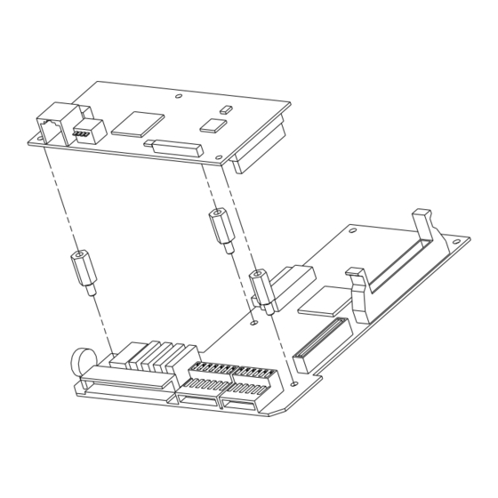
- Page 3 Modbus/TCP Manual 4. Modbus/TCP Appearance and Installation Installing communication card to iP5A inverter...
- Page 4 Modbus/TCP Manual 5. Network Connection Communication cable connecting terminal Pin No. Signal Description Cable color Transmitting data Plus White / Yellow Transmitting data Minus Yellow Receiving data Plus White / Green NONE Not used Blue NONE Not used White / Blue...
- Page 5 Modbus/TCP Manual 6. Network Cable Standard (1) Used Frequency band Category 5 is used. Transmitting speed of category 5 is 100MHz and possible up to 100Mbps. (2) Twisted Pair cable type Classification Detail Used Maximum 200MHz High speed signal cable UTP (U.UTP)
- Page 6 Modbus/TCP Manual 7. Modbus/TCP related Keypad parameter Inverter parameters below display Modbus/TCP related information. iP5A Modbus/TCP related Keypad parameter Code Parameter Initial Setting Description number name value value Communication card installed in inverter is displayed. COM-01 Opt B/D (If Modbus/TCP comm. Card is installed, “Modbus/TCP”...
- Page 7 Modbus/TCP Manual Opt B/D (Option card information, COM-01) The type of communication card installed in inverter is displayed automatically. If iP5A Modbus/TCP communication card is installed, “Modbus/TCP” message is displayed automatically. Opt mode (drive and freq. command setting mode, COM-02)
- Page 8 Modbus/TCP Manual 8. Inverter communication address Refer to iP5A manual appendix C - built-in comm. Parameter list 9. Modbus/TCP Frame (1) Modbus/TCP Frame structure MBAP Header( 7 bytes) PDU (5 bytes ~) Generally, Ethernet uses Ethernet II Frame. MODBUS Application Protocol Header (MBAP Header) MBAP Header structure is as below.
- Page 9 Modbus/TCP Manual (2) Function Code Description Modbus TCP can be divided into Client and Server. Client gives the command and Server responds to the command. Generally, as Client, there are PLC, HMI, PC so on, and Server means inverter.
- Page 10 Modbus/TCP Manual Frame Constitution that Server responds to Master Responded Frame Length Value Function Code 1 Bytes 0x06 Comm. Address 2 Bytes 0x0000 ~ 0xFFFF Data Value 2 Bytes 0x0000 ~ 0xFFFF ③ Write Multiple Register The function is used when modifying consecutive Data from 1 up to 16 inverter (Server).
- Page 11 Modbus/TCP Manual Except Frame Except Frame is for responding from Server if Error happens performing the required Frame when Client sends required Frame to Server. Exception Frame Structure Error Frame Length Value 0x80 + Function Code that Error Code...
- Page 12 If you try to save address that is READ ONLY ADDRESS 0X14 only for reading value, this massage is displayed. This Code only exists at LS inverter. modify modifying WRITE PERMITION ERROR 0x20 prohibited parameter...
- Page 13 Modbus/TCP Manual LED name Color Function BLINK – It means Modbus/TCP communication card Green CPU is operating normally when the power is well supplied to iP5A Modbus/TCP. OFF – It means Modbus/TCP communication card is normal without Error. CPU, ERROR Flashing by turns –...
Need help?
Do you have a question about the iP5A and is the answer not in the manual?
Questions and answers