Table of Contents
Advertisement
Available languages
Available languages
Advertisement
Table of Contents

Subscribe to Our Youtube Channel
Related Manuals for TMC Aquarium REEF-Pump 4000

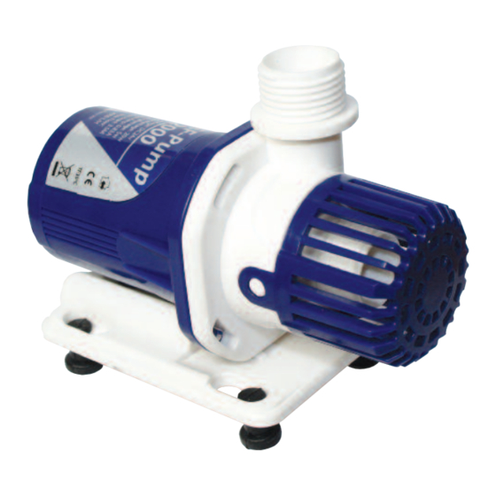
Summary of Contents for TMC Aquarium REEF-Pump 4000
- Page 1 FOR ADVANCED AQUARISTS FOR ADVANCED AQUARISTS ®...
- Page 3 REEF-Pump 2000 REEF-Pump 4000/6000 1 x 15mm 1 x 20mm 1 x 20mm 1 x 25mm ” G1” REEF-Pump 8000 1 x 25mm 1 x 32mm ” REEF-Pump 12000 1 x 25mm 1 x 32mm ”...
- Page 4 - Only use the correctly-rated controller supplied with the pump, for example the REEF-Pump 4000 controller with the REEF-Pump 4000. A label on the back of the controller denotes which pump it is designed for. Using the wrong controller with the wrong pump will invalidate the guarantee.
-
Page 5: Parts List
PARTS LIST Pump strainer Pump feet Pump inlet 10. Controller Pump outlet 11. Power supply unit (PSU) Pump cover 12. Power cable Pump impeller (representative only - actual impeller 13. Adhesive pad for controller may differ) 14. Hosetails Pump body O ring 15. -
Page 6: Installation
INSTALLATION 1. Install the feet in the holes on the underside of the pump body (see photo 1) and attach a hosetail and hosetail O ring as required (see photo 2). 2. Install and secure the REEF-Pump controller in a suitable location where it can be easily accessed and adjusted e.g. -
Page 7: Maintenance
Only use the correctly-rated controller supplied with the pump, for example the REEF-Pump 4000 controller with the REEF-Pump 4000. A label on the back of the controller denotes which pump it is designed for. Using the wrong controller with the wrong pump will invalidate this guarantee. -
Page 8: Instructions D'installation Et D'utilisation
être exposé aux projections d’eau. - Utilisez uniquement le contrôleur aux caractéristiques correctes fourni avec la pompe, par exemple le contrôleur REEF-Pump 4000 pour la pompe REEF-Pump 4000. Une étiquette à l’arrière du contrôleur indique la pompe pour laquelle il est conçu. L’utilisation d’un contrôleur inadapté... -
Page 9: Liste De Pièces
LISTE DE PIÈCES Crépine de pompe Pieds de pompe Admission de pompe 10. Contrôleur Sortie de pompe 11. Bloc d’alimentation (PSU) Couvercle de pompe 12. Câble d’alimentation Turbine de pompe (uniquement à titre d’illustration – 13. Plaquette adhésive pour le contrôleur il se peut que la turbine réelle soit différente) 14. - Page 10 Photo 2 Photo 3 Photo 1...
-
Page 11: Entretien
Utilisez uniquement le contrôleur aux caractéristiques correctes fourni avec la pompe, par exemple le contrôleur REEF-Pump 4000 avec la pompe REEF-Pump 4000. Une étiquette à l’arrière du contrôleur indique la pompe pour laquelle il est conçu. L’utilisation d’un contrôleur inadapté... -
Page 12: Installations- Und Bedienungsanleitung
– Verwenden Sie ausschließlich das mit der Pumpe gelieferte Bediengerät, z. B. das REEF-Pump 4000-Bediengerät für die REEF-Pump 4000. Ein Etikett an der Rückseite des Bediengeräts gibt an, für welche Pumpe es geeignet ist. Bei Verwendung des falschen Netzteils für die jeweilige Pumpe erlischt die Garantie. - Page 13 TEILELISTE 1. Pumpensieb 9. Pumpenfüße 2. Pumpeneinlass 10. Steuereinheit 3. Pumpenauslass 11. Netzteil 4. Pumpendeckel 12. Netzkabel 5. Laufrad (nur zur Darstellung – Abweichungen möglich) 13. Haftplättchen für Bediengerät 6. O-Ring für Pumpengehäuse 14. Rohrstutzen 7. Pumpengehäuse 15. Muffe für Rohrstutzen 8.
- Page 14 INSTALLATION 1. Setzen Sie die Füße in die Löcher an der Unterseite des Pumpengehäuses ein (siehe Foto 1) und bringen Sie einen Rohrstutzen mit O-Ring an, soweit erforderlich (siehe Foto 2). 2. Installieren und befestigen Sie das REEF-Pump-Bediengerät an einer geeigneten Stelle, an der Sie es leicht erreichen und einstellen können, z.
-
Page 15: Wartung
Verwenden Sie ausschließlich das mit der Pumpe gelieferte Bediengerät, z. B. das REEF-Pump 4000-Bediengerät für die REEF-Pump 4000. Ein Etikett an der Rückseite des Bediengeräts gibt an, für welche Pumpe es geeignet ist. Bei Verwendung des falschen Netzteils für die jeweilige Pumpe erlischt diese Garantie. - Page 16 - Gebruik alleen de controller met de juiste nominale waarde die meegeleverd wordt met de pomp, bijvoorbeeld de REEF-Pump 4000 controller met de REEF-Pump 4000. Op de achterkant van de controller ziet u een etiket waarop de pomp staat aangegeven waarvoor deze controller is bedoeld.
-
Page 17: Lijst Van Onderdelen
LIJST VAN ONDERDELEN 1. Pompzeef 9. Poten pomp 2. Pompinlaat 10. Controller 3. Pompuitlaat 11. Voedingseenheid 4. Pompafdekking 12. Voedingskabel 5. Pomprotor (alleen ter illustratie - de feitelijke rotor kan 13. Kleefstrook voor controller er anders uitzien) 14. Slanguiteinden 6. O-ring voor pomplichaam 15. - Page 18 INSTALLATIE 1. Installeer de poten in de gaten aan de onderkant van het pomplichaam (zie foto 1) en bevestig een slanguiteinde en O-ring van het slanguiteinde zoals aangegeven (zie foto 2). 2. Installeer en bevestig de controller voor de REEF-Pump op een geschikte plaats waar deze gemakkelijk te bereiken is en afgesteld kan worden, bijvoorbeeld aan de zijkant of achterkant van uw aquariumkast.
-
Page 19: Problemen Oplossen
Gebruik alleen de controller met de juiste nominale waarde die geleverd wordt bij de pomp, bijvoorbeeld de REEF-Pump 4000 controller met de REEF-Pump 4000. Op de achterkant van de controller ziet u een etiket waarop de pomp staat aangegeven waarvoor deze controller is bedoeld. - Page 20 - Utilizzare esclusivamente l’unità di controllo dalle caratteristiche corrette per la pompa con cui viene fornita: per esempio l’unità di controllo REEF-Pump 4000 viene fornita con la pompa REEF-Pump 4000. Un’etichetta sul retro dell’unità di controllo indica la pompa per la quale è...
-
Page 21: Elenco Componenti
ELENCO COMPONENTI 1. Filtro pompa 9. Piedini pompa 2. Aspirazione pompa 10. Unità di controllo 3. Mandata pompa 11. Alimentatore elettrico (PSU) 4. Calotta pompa 12. Cavo di alimentazione elettrica di rete 5. Girante pompa (solo a scopo rappresentativo: la 13. -
Page 22: Installazione
INSTALLAZIONE 1. Montare i piedini nei fori sul lato inferiore del corpo della pompa (vedere foto 1) e fissare un portagomma e l’eventuale guarnizione toroidale del portagomma (vedere foto 2). 2. Montare e fissare l’unità di controllo della pompa REEF-Pump in un sede idonea che permetta di accedervi e regolarla facilmente, per esempio sul fianco o sul retro dell’armadio dell’acquario, ma assicurandosi che NON risulti montata al di sopra dell’acquario o della vasca di stoccaggio, né... -
Page 23: Manutenzione
Utilizzare esclusivamente l’unità di controllo dalle caratteristiche nominali corrette per la pompa con cui viene fornita: per esempio, l’unità di controllo REEF-Pump 4000 viene fornita con la pompa REEF-Pump 4000. Un’etichetta sul retro dell’unità di controllo indica la pompa per la quale è... - Page 24 - Utilice únicamente el controlador con las características correctas incluido con la bomba, por ejemplo, el controlador REEF-Pump 4000 con la unidad REEF-Pump 4000. Una etiqueta en la parte trasera del controlador indica para qué bomba ha sido diseñado. La utilización de un controlador distinto del correspondiente a la bomba anulará...
-
Page 25: Lista De Piezas
LISTA DE PIEZAS Filtro de la bomba Pies de la bomba Entrada de la bomba 10. Controlador Salida de la bomba 11. Fuente de alimentación (PSU) Tapa de la bomba 12. Cable de alimentación Propulsor de la bomba (solo indicativo: el propulsor 13. -
Page 26: Montaje
MONTAJE 1. Monte las patas en los orificios de la parte inferior del cuerpo de la bomba (consulte la foto 1) y fije un conector de manguera y su junta tórica adecuadamente (consulte la foto 2). 2. Monte y fije el controlador REEF-Pump en una posición adecuada donde sea fácilmente accesible y ajustable, por ejemplo en el lateral o el dorso del armario de su acuario, asegurándose de que NO se monta sobre el acuario ni el colector, ni en ninguna posición en la que pueda caer accidentalmente al agua o resultar salpicado por la misma. -
Page 27: Mantenimiento
Utilice únicamente el controlador con las características correctas incluido con la bomba, por ejemplo, el controlador REEF-Pump 4000 con la unidad REEF-Pump 4000. Una etiqueta en la parte trasera del controlador indica para qué bomba ha sido diseñado. La utilización de un controlador no correspondiente a la bomba anulará... - Page 28 – Utilize exclusivamente o controlador com as especificações corretas fornecido com a bomba, por exemplo, o controlador da REEF-Pump 4000 com a REEF-Pump 4000. Uma etiqueta na parte de trás do controlador indica qual a bomba para a qual foi concebido. A utilização do controlador errado com a bomba errada invalidará...
-
Page 29: Lista De Peças
LISTA DE PEÇAS Filtro de rede da bomba Pés da bomba Entrada da bomba 10. Controlador Saída da bomba 11. Unidade de alimentação (PSU) Cobertura da bomba 12. Cabo de alimentação Rotor da bomba (imagem representativa, o rotor real 13. Suporte autocolante para o controlador pode ser diferente) 14. - Page 30 INSTALAÇÃO 1. Monte os pés nos orifícios no lado debaixo do corpo da bomba (ver fotografia 1) e, se necessário, ligue um conetor de mangueira e um o-ring de conetor de mangueira (ver fotografia 2). 2. Instale e fixe o controlador da REEF-Pump num local adequado onde possa ser facilmente acedido e ajustado, por exemplo, na lateral ou na parte de trás do armário do seu aquário, mas tendo o cuidado de NÃO montar acima do aquário ou do sump, nem em qualquer posição onde possa cair acidentalmente na água ou corra o risco de ser salpicado com água.
-
Page 31: Resolução De Problemas
Utilize exclusivamente o controlador com as especificações corretas fornecido com a bomba, por exemplo, o controlador da REEF-Pump 4000 com a REEF-Pump 4000. Uma etiqueta na parte de trás do controlador indica qual a bomba para a qual foi concebido. A utilização do controlador errado com a bomba errada invalidará... - Page 32 ® Tropical Marine Centre, Solesbridge Lane, Chorleywood, Hertfordshire,WD3 5SX. Technical Information Lines Tel: +44 (0) 1923 284151 Fax: +44 (0) 1923 285840 Open between 9am - 5pm Monday to Thursday/9am - 12pm Friday. www.tropicalmarinecentre.co.uk tmc@tropicalmarinecentre.co.uk v.1/2016...
Need help?
Do you have a question about the REEF-Pump 4000 and is the answer not in the manual?
Questions and answers