Table of Contents
Advertisement
Quick Links
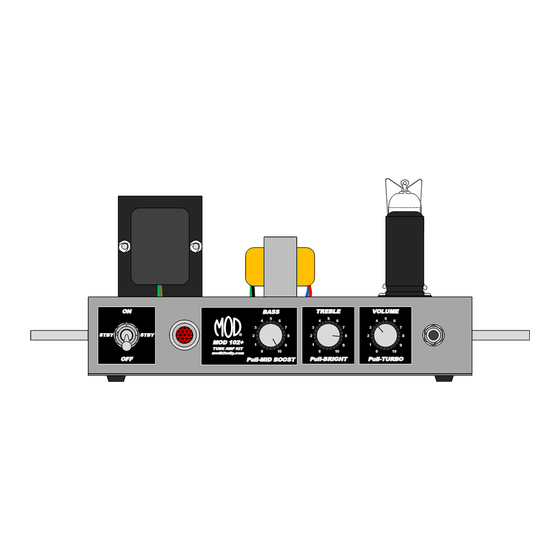
MOD 102+ GUITAR AMP KIT (K-MOD102+)
ON
STBY
OFF
Use these instructions to learn:
How to build a tube amp.
This tube guitar amplifier circuit is based on a classic American circuit design combined with a British style
class A output section. At low volume it produces a clean chimey tone that moves into smooth overdrive at
higher volumes.
+ features include a three position progressive toggle switch for off-standby-power and additional push-pull
functionality for each control:
Pull out the bass control knob for "mid boost."
Pull out the treble control knob for "bright."
Pull out the volume control knob for "turbo."
STBY
®
MOD 102+
TUBE AMP KIT
modkitsdiy.com
TREBLE
BASS
5
5
4
6
4
6
3
7
3
7
2
8
2
8
1
9
1
9
0
10
0
10
Pull-BRIGHT
Pull-MID BOOST
1
Copyright © 2015 by modkitsdiy.com
VOLUME
5
4
6
3
7
2
8
1
9
0
10
Pull-TURBO
Advertisement
Table of Contents

Summary of Contents for Mod 102+
- Page 1 MOD 102+ GUITAR AMP KIT (K-MOD102+) TREBLE VOLUME BASS STBY STBY ® MOD 102+ TUBE AMP KIT modkitsdiy.com Pull-BRIGHT Pull-TURBO Pull-MID BOOST Use these instructions to learn: How to build a tube amp. This tube guitar amplifier circuit is based on a classic American circuit design combined with a British style class A output section.
-
Page 2: Table Of Contents
TABLE OF CONTENTS TOOL LIST …………………………………………………………………………...3 PARTS LIST …………………………………………………………………………...4 SAFETY …………………………………………………………………………...5 SOLDERING TIPS …………………………………………………………………...6 WIRING TIPS ……………………………………………........7 HARDWARE FASTENING TIP …………………………………………………...8 STEP BY STEP ASSEMBLY INSTRUCTIONS …………………………………...8 Section 1 - Mounting of Top Components …………………………………...8 Section 2 - Mounting of Front Components ………………………………….10 Section 3 - Mounting of Rear Components …………………………………...11 Section 4 - Mounting Terminal Strips and Components ………………………11 Section 5 - Connect Rear Mounted Components ……………………………..15... -
Page 3: Tool List
MOD 102 GUITAR AMP KIT – BACKGROUND The MOD 102+ Guitar Amp Kit was designed for anyone who is interested in building their own tube guitar amplifier head. It is meant for practice amp volume (up to 8 Watts). It has an 8 ohm output impedance. (We recommend using it with a speaker cabinet that has an overall power handling of at least 10W). -
Page 4: Parts List
PARTS LIST Please see the parts list drawings for help with finding and identifying each part along with corresponding part numbers. RESISTORS: HARDWARE: Description Quantity Description Quantity 100Ω #8 self-tap screws 150Ω #6 screws 470Ω #6 hex nuts 1.5kΩ 1/2W #6 lock washers 5.6kΩ... -
Page 5: Safety
Visit www.modkitsdiy.com and e-mail info@modkitsdiy.com if you have any problems when first turning on your amp for troubleshooting help. If you smell or see smoke, hear something pop, or the chassis becomes too hot to touch, turn off power and unplug immediately. SAFETY Tube amps operate at high voltages that have the potential to injure and kill. -
Page 6: Soldering Tips
SOLDERING TIPS It is important to make a good solder joint at each connection point. A cold solder joint is a connection that may look connected but is actually disconnected or intermittently connected. (A cold solder joint can keep your project from working.) Follow these tips to make a good solder joint. -
Page 7: Wiring Tips
WIRING TIPS Because of the electro-magnetic A) Twisted Wires properties of current traveling through a wire, there are wiring conventions used when making wire connections. A) Twist the wires together where indicated in the instructions. B) If two wire paths intersect, try to have them cross over each other as B) Perpendicular perpendicular as possible. -
Page 8: Hardware Fastening Tip
HARDWARE FASTENING TIP When fastening components with mounting hardware (screws, lock washers, and hex nuts), the lock washer and hex nuts should be fastened on the other side of the chassis from the head of the screw in the order pictured below. - Page 9 Step 4 – Mount the 9 pin miniature tube socket with its retainer for the EL84 Drawing 2 shows where to mount the 9 pin miniature socket “V2” and its retainer. Make sure that pins 1 & 9 face the “TR1” side of the chassis. (Use #4 hardware). Step 5 –...
-
Page 10: Section 2 - Mounting Of Front Components
Step 7 – Mount the Output Transformer (TR2) Drawing 3 shows where to mount the output transformer P-T31. A) Hold the transformer up above the chassis and push the wires through their respective grommet holes as indicated on the drawing. B) Place the transformer on the chassis so that the mounting holes line up with the transformer feet. -
Page 11: Section 3 - Mounting Of Rear Components
When all three pots are mounted, turn their shafts all the way counter-clockwise. (Once you have done this, you can mount the knobs while pointing to “0” and tightening their set screws). Set screw Step 4 – Mount the Input Jack Drawing 4 shows where to mount the input jack. - Page 12 Step 2 – Solder Components to Their Terminal Strip Locations Please see page 6 “Soldering Tips” if you are new to making solder connections. Drawing 6 shows each component and its respective location on the terminal strip. Be sure to follow the same orientation of polarity as shown in the drawing for diodes and polarized electrolytic capacitors.
- Page 13 Connect the T3 and bass pot components: The bass and treble controls are dual 250K pots with a DPDT push-pull switch attached. Unused front potentiometer The front pot section, closest to the front panel, will not be used. The DPDT lug section numbering is shown in the drawings.
- Page 14 Connect the volume pot and input jack components: 1) Connect a 3" piece of white wire from the volume pot’s cold lug to the input jack’s sleeve lug, but do not solder at the sleeve lug, yet. 2) Connect a 1 ½" piece of white wire from the volume pot’s hot lug to turbo switch lug 1. 3) Connect a 2 ½"...
-
Page 15: Section 5 - Connect Rear Mounted Components
Connect T6 and V2 components: 1) Connect the 470Ω resistor from T6(5) to V2 pin 9. 2) Connect the 5.6kΩ resistor from T6(3) to V2 pin 2. 3) Connect the .022µF cap with from T6(3) to T5(3). 4) Connect the remaining 220kΩ resistor from T6(3) to T6(1). 5) Connect the 150Ω, 5 watt resistor from T6(1) to V2 pin 3, but do not solder at pin 3, yet. -
Page 16: Section 6 - Connect The Tube Filament Wiring
Insert and connect the power cord: 1) Install the grommet with ¼” center into the rear chassis hole. 2) Gently insert the power cord through this grommet hole until at least 18" (1.5 FT) are through. Tie a knot at the end of the cord so that 1" of black outside insulation extends past the knot. This knot will serve as a strain relief. - Page 17 Plug it in, turn it on and play! The MOD 102 has a single-ended (class A), cathode biased output stage. There is no need to check the bias, just plug the amp in, connect the output to a proper 8 ohm load, let the tubes heat up on standby for at least 30 seconds and it’s ready to play.
-
Page 18: Label Mounting Instructions
Label Mounting Instructions The labels are meant to be placed over their respective chassis holes indicated below. There are four labels for the front panel and two labels for the rear panel. Tip: For longer lasting labels with a plexi-like appearance, add a transparent lamination over the front of the labels by covering them with clear packing tape prior to cutting the labels.
Need help?
Do you have a question about the 102+ and is the answer not in the manual?
Questions and answers