Advertisement
Series
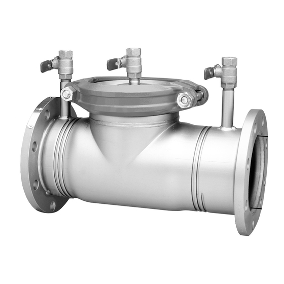
775/775DCDA
Double Check Backflow Preventer
Double Check Detector Assemblies
Sizes: 3" - 8"
CALIFORNIA PROPOSITION 65 WARNING
WARNING: This product contains chemicals
known to the State of California to cause cancer
and birth defects or other reproductive harm.
(Installer: California law requires that this
warning be given to the consumer.)
Insert lid bolts in holes
provided to remove 1st check
• Installation • Service
• Repair Kits • Maintenance
For field testing procedure, send for IS-TK-DP/DL,
IS-TK-9A, IS-TK-99E and IS-TK-99D.
For other repair kits and service parts, send for
PL-RP-BPD.
For technical assistance, contact your local Watts
representative on back page.
N775/N775DCDA Backflow Preventers are
identical in construction to 775/775DCDA Series
except include short radius elbows between
backflow preventer flange and gate valve flange.
IMPORTANT: Inquire with governing authorities
for local installation requirements.
NOTE: For Australia and New Zealand: Pipeline
strainers should be installed between the up-
stream shutoff valve and the inlet of the
backflow preventer.
LIMITED WARRANTY: Watts Regulator Company warrants each prod-
uct against defects in material and workmanship for a period of one year
from the date of original shipment. In the event of such defects within
the warranty period, the Company will, at its option, replace or recondi-
tion the product without charge. This shall constitute the exclusive
remedy for breach of warranty, and the Company shall not be respon-
sible for any incidental or consequential damages, including without
limitation, damages or other costs resulting from labor charges, delays,
vandalism, negligence, fouling caused by foreign material, damage from
adverse water conditions, chemicals, or any other circumstances over
which the Company has no control. This warranty shall be invalidated by
any abuse, misuse, misapplication or improper installation of the
product. THE COMPANY MAKES NO OTHER WARRANTIES EXPRESS
OR IMPLIED EXCEPT AS PROVIDED IN THIS LIMITED WARRANTY.
RP/IS-775/775DCDA
Advertisement
Table of Contents

Related Manuals for Watts 775 Series


Summary of Contents for Watts 775 Series
- Page 1 (Installer: California law requires that this warning be given to the consumer.) LIMITED WARRANTY: Watts Regulator Company warrants each prod- uct against defects in material and workmanship for a period of one year from the date of original shipment. In the event of such defects within the warranty period, the Company will, at its option, replace or recondi- tion the product without charge.
- Page 2 Basic Installation Instructions Watts Series 775 Double Check Valve Installation Note: The flange gasket bolts for the gate valves should be retight- ened during installation as the bolts may have loosened due to #3 Test Cock storage and shipping. #4 Test Cock...
- Page 3 The number of assemblies used in parallel should be determined by the engineer’s judgement based on the operating conditions of a specific in- stallation. Watts 775 *For additional information on Watts insulated enclosures send for ES-WB or ES-WBT.
- Page 4 Removing Checks Before Servicing Be Certain Shutoff Valves Are Closed Valve outlet flange Threaded stud on flange Figure 6 Figure 2 Figure 1 No. 2 Cam Check No. 1 Cam Check (6" and 8" models only) The assembly may be locked open by aligning the holes Place yourself so that the water flow through the valve is in the cam bar and hinge arms and inserting a rod (see left to right.
- Page 5 Watts Series 775/775DCDA 3" - 8" Figure 3 Cover Plate Figure 4 Groove Coupler Gasket Ball Valve Groove Coupler Ball Valve No. 1 Check Assembly Figure 5 No. 2 Cam-Check Assembly No. 1 Cam-Check 2nd Cam-check Assembly 1st Cam-check O-ring (removable) O-ring (removable) No.
- Page 6 Check Parts and Disassembly Check Parts Item No. Part Description First Check O-ring (removable) Clapper Assembly (removable) Clapper Retaining Plate Screws (removable) Clapper Retainer Plate (removable) Clapper Disc (removable) Pivot Arm Pin (removable ) Two c-clips Note: Align holes and insert pin or small Second Check O-ring (removable) screwdriver to hold in...
- Page 7 The following Test Procedure is one of several that is recognized throughout the United States for verifica- tion of the functioning of Backflow preventers. The following procedure is not a specific recommendation. The Watts series of test kits are capable of per- forming any of the recognized Backflow test procedures.
Need help?
Do you have a question about the 775 Series and is the answer not in the manual?
Questions and answers