Table of Contents
Advertisement
Available languages
Available languages
Operator's manual Manuel d'utilisation Gebruiksaanwijzing Istruzioni per l'uso
Manual de instrucciones Bedienungsanweisung Instruções para o uso
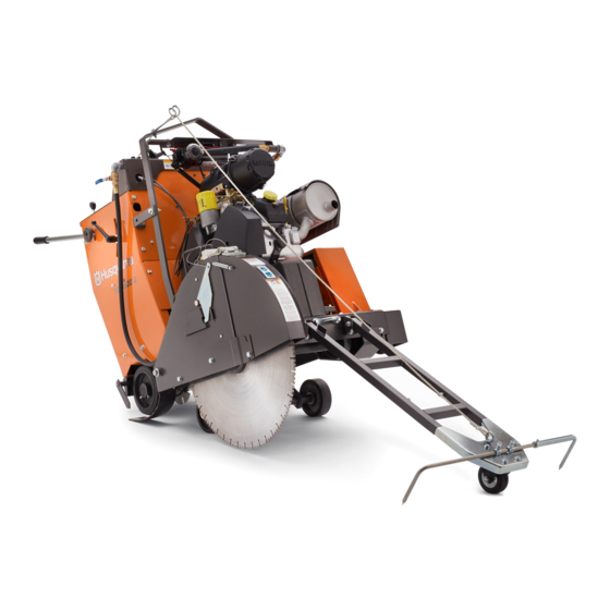
FS 3500 G
Please read the operator's manual carefully and make sure you understand the instructions before using the machine.
Lire attentivement et bien assimiler le manuel d'utilisation avant d'utiliser la machine.
Neem de gebruiksaanwijzing grondig door en gebruik de machine niet voor u alles duidelijk heeft begrepen.
Prima di usare la macchina, leggere per intero le istruzioni per l'uso e accertarsi di averne compreso il contenuto.
Lea detenidamente el manual de instrucciones y asegúrese de entender su contenido antes de utilizar la máquina.
G G G G B B B B F F F F R R R R N N N N L L L L I I I I T T T T
Lesen Sie die Bedienungsanweisung sorgfältig durch und machen Sie sich mit dem Inhalt vertraut, bevor Sie das Gerät
E E E E S S S S D D D D E E E E P P P P T T T T
benutzen.
Leia as instruções para o uso com toda a atenção e compreenda o seu conteúdo antes de fazer uso da máquina.
Advertisement
Chapters
Table of Contents
Troubleshooting

Related Manuals for Husqvarna FS 3500 G


Summary of Contents for Husqvarna FS 3500 G
- Page 1 Operator’s manual Manuel d’utilisation Gebruiksaanwijzing Istruzioni per l’uso Manual de instrucciones Bedienungsanweisung Instruções para o uso FS 3500 G Please read the operator’s manual carefully and make sure you understand the instructions before using the machine. Lire attentivement et bien assimiler le manuel d’utilisation avant d’utiliser la machine.
-
Page 2: Key To Symbols
KEY TO SYMBOLS Symbols on the machine: Lower blade Some of the symbols below refer to the CE market. WARNING! The machine can be a dangerous tool if used incorrectly or carelessly, which can Switch for lower and raise the blade cause serious or fatal injury to the operator or others. -
Page 3: Explanation Of Warning Levels
KEY T O SYMBOLS Explanation of warning le vels Alw ays use the machine mounted lifting eye when lifting. The w arnings are graded in three levels. W ARNING! This product is in accordance with applicable EC directives. If marked on the machine. W ARNING! Used if there is a risk of serious injury or death for the operator or damage to Noise emission to the environment according... -
Page 4: Table Of Contents
EC Declaration of Conformity ........Dear Customer, ............Design and features ............. FS 3500 G ..............What is what on the floor saw - FS 3500 G ....What is what on the control panel? ......MACHINE´S SAFETY EQUIPMENT General ................ -
Page 5: Presentation
Husqvarna is the global leader in outdoor power products for forestry, park maintenance and lawn and garden care, as well as cutting equipment and diamond tools for the construction Sa w and stone industries. -
Page 6: What Is What On The Floor Saw - Fs 3500 G
PRESENT A TION What is what on the fl oor saw - FS 3500 G 6 – English... - Page 7 PRESENT A TION 1 Front guide 45 Engine throttle 46 Water valve 2 Engine oil check (dipstick) 47 Locking knob for handlebar adjustment in height 3 Air filter 4 Working lights (accessory) 48 Flow control valve 5 Fuel tank fill 49 Rear pointer - right side 6 Handle bar 50 Transport wheel...
-
Page 8: What Is What On The Control Panel
PRESENT A TION The control panel is the oper ator’s link to the machine. From here the operator can control anything from engine rpm, cutting depth of the blade and read the current status of the engine and the machine. What is what on the contr ol panel? 8 Blade depth stop 9 Choke control... -
Page 9: Machine´s Safety Equipment
MA CHINE´S SAFETY EQ UIPMENT General • Start the engine, turn the Engine start switch to ignition on position. Follow the procedure in the engine manual. WARNING! Never use a machine that has faulty safety equipment! If your machine fails any checks contact your service agent to get it repaired. - Page 10 MACHINE´S SAFETY EQUIPMENT Protection covers and guards Muffler WARNING! Always check that the protection WARNING! Never use a machine without a covers are correctly fitted before starting the muffler, or with a faulty muffler. A damaged machine. muffler may substantially increase the noise level and the fire hazard.
-
Page 11: Blades
BLADES General • When using diamond blades make sure that it rotates in the direction indicated by the arrow on the blade. WARNING! A cutting blade may burst and cause injury to the operator. The cutting blade manufacturer issues warnings and recommendations for the use Sharpening diamond blades and proper care of the cutting blade. -
Page 12: Fuel Handling
FUEL HANDLING General Fueling WARNING! Running an engine in a confined WARNING! Always stop the engine and let it or badly ventilated area can result in death cool for a few minutes before refuelling. due to asphyxiation or carbon monoxide poisoning. -
Page 13: Battery Handling
BATTERY HANDLING General 4 Connect negative terminal. WARNING! Lead-acid batteries produce explosive gases. Avoid sparks, open flames and smoking close to batteries. • Connecting or disconnecting the battery may cause sparks and short circuits. • A spark or flame can cause a lead acid battery to explode. •... -
Page 14: Operating
Cutting generates drugs, medication or anything that could sparks that can ignite clothing. Husqvarna recommends affect your vision, alertness, coordination or that you wear flame-retardant cotton or heavy denim. Do judgement. -
Page 15: Basic Working Techniques
OPERATING Basic working techniques WARNING! Unauthorized modifications and/ or accessories may lead to serious injury or • This machine is designed and intended for cutting of fresh death to the user or others. Under no and hardened concrete in different hardness classes and circumstances may the design of the of asphalt. -
Page 16: Moving The Machine
OPERATING • Turn handle adjustment locking knob B counterclockwise • Raise the saw until the two rear wheels clears the surface. to unlock and reposition handlebar. Turn clockwise to lock The saw can now be moved by standing behind it and handlebar in position. -
Page 17: Fitting The Blade
OPERATING • Pull out the Engine Choke. Adjust the resistance on the Forward/Reverse control lever with the nut on the side of the lever. • Turn the Engine start switch to the engines start position until the engine starts, then release the switch. It will return to ignition on position automatically. - Page 18 OPERATING • Loosen the blade guard front bolt and lift the blade guard 1 Loosen blade shaft bolt which is used to clamp the blade latch. between the inner and outer flange. • Raise the blade guard front. 2 Remove outer flange and plain washer. 3 Fit diamond blade to outer flange arbor.
-
Page 19: Blade Cutting Depth
OPERATING • Tighten the blade shaft bolt firmly using the blade shaft 3 Move the blade guard lock forward until it stops and wrench while resistance between diamond blade and unlatches. Lift the blade guard with its handle off the ground helps to achieve proper and final tightening. -
Page 20: Straight Line Sawing
OPERATING • Rotate the Blade Depth Indicator knob to the zero Rear axle adjustment position. The blade cutting depth will now be indicated on the Depth Indicator when the blade is lowered into the NOTICE! First loosen the bolts on the rear axle and the cutting surface. -
Page 21: Long-Term Storage
OPERATING Transport Close the fuel shut-off valve and reinstall the rear protective cover. • Grease all nipples before storage. WARNING! Always remove the cutting blade before transporting the machine outside the • Disconnect negative terminal and secure in safe distance cutting area. -
Page 22: Starting And Stopping
STARTING AND STOPPING Before starting • Lower the front guide and align the front guide, rear guide and the diamond blade with the line on the surface. The front guide is telescopic, adjust the length with the screws on the inside of the front guide. WARNING! Please read the operator’s manual carefully and make sure you understand the instructions before using the... - Page 23 STARTING AND STOPPING Water safety system • Shift the Forward/Reverse control lever into gear. Water is used to prevent overheating the blade while controlling the dust that results from sawing. The water safety system monitors the water pressure to the machine and interrupts the sawing process if the pressure drops.
-
Page 24: Stopping
STARTING AND STOPPING Stopping WARNING! Always keep all parts of your body away from blade and all other moving parts. Stop the cutting • Put Forward/Reverse control lever into the Stop/Neutral position. • Raise the diamond blade out of the cut by pressing the Raise/lower switch on the control lever upward until the diamond blade clears the surfaces. -
Page 25: Maintenance And Service
MAINTENANCE AND SERVICE General Cleaning WARNING! Most accidents involving CAUTION! When cleaning the machine there machines occur during trouble shooting, is a risk of getting dirt and harmful service and maintenance as staff have to substances in the eyes, for example. locate themselves within the machine’s risk Dirt and harmful substances can be released area. - Page 26 MAINTENANCE AND SERVICE • Always park the machine on a level surface with the engine OFF and the Engine start switch set in the STOP position before performing any maintenance. Press the Machine stop on the control panel. Please read the engine manual for your machine carefully and make sure you understand the instructions before using the machine.
- Page 27 MAINTENANCE AND SERVICE Daily maintenance Check all hoses and clamps for damage or looseness. The image only shows some of the hoses and clamps. WARNING! Switch off the engine before carrying out any checks or maintenance. Check engine oil level without blade and the saw horizontal for a flat saw level.
- Page 28 MAINTENANCE AND SERVICE Check the water spray over the diamond blade. Lubricate the seal with a few drops of oil prior to refitting it. • Raise blade guard front and use quick release pin to lock it in upright position. •...
- Page 29 MAINTENANCE AND SERVICE • Use 19 mm. wrench to slightly loosen the screw that fix Replace engine oil and filter the tension device to the plate. See instructions under the heading ”After the first 50 hours” Check wheels for wear or damage. Check rear wheels for looseness Check engine air cleaner hose and clamps Check hydraulic system fluid level...
-
Page 30: Disposal, Scrapping
MAINTENANCE AND SERVICE • Refill the reservoir with new oil. Ensure that the machine Lubricate blade shaft on top of the base plate. is fully lowered. NOTICE! Do not overfill! Yearly maintenance Disposal, scrapping Replace outer and inner air filter This product should be submitted to an appropriate recycling Remove the rear cover by opening the 2 air filter housing station in accordance with local requirements. -
Page 31: Troubleshooting
TROUBLESHOOTING Incidents during sawing CAUTION! If the engine or blade stops for any reason, raise the blade completely from the cut. Set the Engine start switch to STOP position. Press the Machine stop on the control panel. Inspect the machine thoroughly before restarting the engine. •... -
Page 32: Technical Data
TECHNICAL DATA Battery FS 3500 G Terminal type Standard SAE Voltage, V CCA, A Maximum size (LxWxH), mm/inch 242x175x175 / 9 9/16x6 7/8x6 7/8 Hydraulic fluid and lubricants Hydraulic fluid Quality Standard API Class SE SAE 10W-30 API Class CC... -
Page 33: Technical Data
TECHNICAL DATA Technical data FS 3500 G , y t , t f Approximate blade shaft output, hp/kW 29/21.6 fl Ø Blade shaft diameter, mm/inch 44.45 / 1-3/4 , mm/inch o l l l l a y l l Blade guard attachment Slip-on, auto-latch Electro-hydraulic pump raises blade;... - Page 34 TECHNICAL DATA Saw dimensions Saw length (pointer up, handles extented), A Width, mm/inch 807 / 31 3/4 1977 / 77 3/4 mm/inch Front 502 / 19 3/4 Center to center wheel width, Min. overall height (no exhaust pipe, no pre- 1152 / 45 3/8 mm/inch cleaner cap), mm/inch...
-
Page 35: Noise Emissions
TECHNICAL DATA Engine FS 3500 G Engine specifications Kohler CH1000 Max. engine output (see note 1) 37hp@3750rpm (27.5kW@3750rpm) Displacement, dm / cu.in. 1.0/61 Cylinders Stroke, mm / in. 78.5/3.1 Fuel tank capacity, l / gallon 23.8/6.3 Air filter Cyclon air filter and restriction indicator... -
Page 36: Relays And Fuses
RELAYS AND FUSES Relays and fuses - FS 3500 G Function Designation Ampere Main system Ignition Hydraulic System Engine carb solenoid Instruments Water pump kit (optional) Light kit (optional) Power outlet kit (optional) Main relay Supress relay Oil sentry relay 36 –... -
Page 37: Ec Declaration Of Conformity
Husqvarna AB, SE-561 82 Huskvarna, Sweden, tel +46-36-146500, declares under sole responsibility that the flat saw Husqvarna FS 3500 G from 2018’s serial numbers and onwards (the year is clearly stated in plain text on the rating plate with subsequent serial number), complies with the requirements of the COUNCIL’S DIRECTIVES: •... -
Page 38: Explication Des Symboles Symboles Sur La Machine
EXPLICATION DES SYMBOLES Symboles sur la machine: Mise en garde, risque de coupure Certains symboles indiqués ci-dessous s’appliquent au marché européen. Réglage de l’alimentation en eau AVERTISSEMENT! La machine utilisée de manière imprudente ou inadéquate peut devenir un outil dangereux, pouvant causer Lame inférieure des blessures graves voire mortelles à... -
Page 39: Explication Des Niveaux D'avertissement
EXPLICATION DES SYMBOLES Explication des niveaux Frein de stationnement d'avertissement Activé / Désactivé Il existe trois niveaux d'avertissement. AVERTISSEMENT! Maintenez la scie de niveau, sans la lame, lorsque vous vérifiez le niveau d’huile. AVERTISSEMENT! Symbole utilisé en cas de risque de blessures très graves ou de mort pour l'utilisateur ou de dommages pour les Pour soulever la machine, toujours utiliser environs si les instructions du manuel ne... -
Page 40: Sommaire
Déclaration CE de conformité ........Cher client, ..............Conception et propriétés ..........FS 3500 G ..............Éléments de la scie à lame plate – FS 3500 G .... Éléments du panneau de commande ......ÉQUIPEMENT DE SÉCURITÉ DE LA MACHINE Généralités .............. -
Page 41: Présentation
FS 3500 G Plus de 300 ans d'innovation Husqvarna AB est une entreprise suédoise qui a vu le jour en 1689 lorsque le roi Karl XI décida de construire un arsenal pour la fabrication des mousquets. À l'époque, les compétences en ingénierie à... -
Page 42: Éléments De La Scie À Lame Plate - Fs 3500 G
PRÉSENTATION Éléments de la scie à lame plate – FS 3500 G 42 – French... - Page 43 PRÉSENTATION 1 Guide avant 44 Commande de starter 45 Commande des gaz 2 Vérification du niveau d’huile moteur (jauge d’huile) 3 Filtre à air 46 Vanne d’eau 4 Éclairage de travail (accessoire) 47 Bouton de verrouillage pour le réglage de la hauteur de la poignée.
-
Page 44: Éléments Du Panneau De Commande
PRÉSENTATION Le panneau de commande est l’élément qui relie l’opérateur à la machine. À partir de ce panneau, l’opérateur peut contrôler la vitesse de rotation du moteur en tours par minute, commander la profondeur de coupe de la lame et afficher l’état actuel du moteur et de la machine. -
Page 45: Équipement De Sécurité De La Machine
ÉQUIPEMENT DE SÉCURITÉ DE LA MACHINE Généralités • Démarrez le moteur, tournez le commutateur de démarrage du moteur à la position de contact. Suivez la procédure indiquée dans le manuel d’utilisation du moteur. AVERTISSEMENT! Ne jamais utiliser une machine dont les équipements de sécurité sont défectueux. - Page 46 ÉQUIPEMENT DE SÉCURITÉ DE LA MACHINE Capots de protection et protections Silencieux AVERTISSEMENT! Vérifiez toujours que les AVERTISSEMENT! N'utilisez jamais une capots de protection sont montés machine sans silencieux ou avec un correctement avant de démarrer la machine. silencieux défectueux. Si le silencieux est défectueux, le niveau sonore et le risque Les capots de protection de la machine protègent l’utilisateur d’incendie augmentent considérablement.
-
Page 47: Lames
LAMES Généralités • En cas d'utilisation d'une lame diamant, veiller à ce qu'elle tourne dans la direction des flèches sur la lame. AVERTISSEMENT! Un disque de coupe peut se briser et blesser gravement l’utilisateur. Le fabricant du disque découpeur émet des avertissements et des recommandations pour l’utilisation et l’entretien adéquats du Affûtage des lames diamant... -
Page 48: Manipulation Du Carburant
MANIPULATION DU CARBURANT Généralités Remplissage de carburant AVERTISSEMENT! Faire tourner un moteur AVERTISSEMENT! Arrêter le moteur et le dans un local fermé ou mal aéré peut causer laisser refroidir pendant quelques minutes la mort par asphyxie ou empoisonnement au avant de faire le plein. monoxyde de carbone. -
Page 49: Manipulation De La Batterie
MANIPULATION DE LA BATTERIE Généralités 3 Branchez toujours la borne positive en premier. 4 Branchez la borne négative. AVERTISSEMENT! Les batteries plomb- acide génèrent des gaz explosifs. Éviter les étincelles, les feux ouverts et de fumer près des batteries. • Le branchement ou le débranchement de la batterie peut causer des étincelles et des courts-circuits. -
Page 50: Commande
à crée des étincelles qui peuvent enflammer les vêtements. l’utilisateur et aux autres personnes Husqvarna vous recommande de porter du coton ignifugé présentes. ou du denim épais. Ne portez pas de vêtements Ne jamais permettre à des enfants ou à des composés de matières comme le nylon, le polyester ou la... -
Page 51: Techniques De Travail De Base
COMMANDE • Assurez-vous qu'aucun tuyau ou câble électrique ne AVERTISSEMENT! Toute modification non passe par la zone de travail ou dans le matériau à autorisée et/ou tout emploi d’accessoires découper. non homologués peuvent provoquer des • Faire tourner un moteur dans un local fermé ou mal aéré accidents graves voire mortels pour peut causer la mort par asphyxie ou empoisonnement au l’utilisateur et les autres. -
Page 52: Déplacement De La Machine
COMMANDE • Desserrez le bouton de verrouillage A pour régler la • Tournez le bouton de verrouillage dans le sens antihoraire longueur. Poignée de réglage de la longueur de travail pour déverrouiller la roue libre et la repositionner en mode plus confortable. -
Page 53: Montage De La Lame
COMMANDE • Placez le levier de commande de marche avant et arrière Réglez la résistance sur le levier de commande de marche à la position d’arrêt ou neutre. Le moteur ne démarre pas avant et arrière à l’aide de l’écrou sur le côté du levier. si le levier n’est pas dans la position d’arrêt ou neutre. - Page 54 COMMANDE • Desserrez le boulon avant du protège-lame et relevez le 1 Desserrez le boulon de l’arbre de disque servant à serrer loquet du protège-lame. le disque entre les brides intérieure et extérieure. • Soulevez la partie avant du protège-lame. 2 Retirez la bride extérieure et la rondelle plate.
-
Page 55: Profondeur De Coupe
COMMANDE • Serrez fermement le boulon de l’arbre de lame à l’aide de Retrait du protège-lame la clé d’arbre de lame alors que la résistance entre la lame 1 Débranchez le flexible d'eau du protège-lame. de diamant et le sol aide à atteindre le serrage approprié et final. -
Page 56: Sciage En Ligne Droite
COMMANDE • Tournez le bouton de l’indicateur de profondeur à la Sciage en ligne droite position zéro. La profondeur de coupe sera maintenant indiquée sur l’indicateur de profondeur quand la lame est Lors de la coupe, la lame crée une résistance à la force abaissée dans la surface de coupe. -
Page 57: Transport Et Rangement
COMMANDE Transport et rangement Remisage Stockez l'équipement dans un endroit verrouillé afin de le • Retirez la lame avant le transport ou l’entreposage de la maintenir hors de portée des enfants et de toute personne machine pour éviter d’endommager la lame. incompétente. -
Page 58: Démarrage Et Arrêt
DÉMARRAGE ET ARRÊT Avant le démarrage • Abaissez le guide avant et alignez le guide avant, le guide arrière et la lame de diamant avec la ligne sur la surface. Le guide avant est télescopique; réglez la longueur des vis à l’intérieur du guide avant. AVERTISSEMENT! Lire attentivement et bien assimiler le manuel d’utilisation avant d’utiliser la machine. - Page 59 DÉMARRAGE ET ARRÊT Système de sécurité d’eau • Enclenchez le levier de commande de marche avant et arrière. L’eau est utilisée pour prévenir la surchauffe de la lame tout en contrôlant la poussière causée par le sciage. Le système de sécurité d’eau contrôle la pression d’eau de la machine et interrompt le processus de sciage en cas de chute de pression.
-
Page 60: Arrêt
DÉMARRAGE ET ARRÊT Arrêt AVERTISSEMENT! Gardez toujours toutes les parties du corps éloignées de la lame et de toutes les autres pièces mobiles. Arrêter la coupe. • Placez le levier de commande de marche avant et arrière à la position d’arrêt ou neutre. •... -
Page 61: Entretien Et Réparation
ENTRETIEN ET RÉPARATION Généralités Environnement de travail • Il ne doit pas y avoir de poussière dans la zone autour de la machine, afin d'éviter les risques de dérapage. AVERTISSEMENT! La plupart des accidents impliquant des machines se produisent lors Nettoyage de dépannages, de réparations ou de travaux d'entretien, lorsque qu'un membre... -
Page 62: Programme D'entretien
ENTRETIEN ET RÉPARATION Programme d’entretien Le programme d'entretien se base sur la durée de fonctionnement de la machine. Il peut être nécessaire d'entretenir la machine plus fréquemment en cas d'utilisation dans des milieux poussiéreux ou chauds, et d'autant plus si le travail génère des températures élevées. - Page 63 ENTRETIEN ET RÉPARATION Entretien quotidien Vérifiez si les flexibles et les colliers de serrage sont endommagés ou desserrés. L’illustration montre seulement certains flexibles et colliers de AVERTISSEMENT! Tout contrôle et/ou serrage. entretien doit être effectué avec le moteur à l’arrêt. Vérifiez le niveau d’huile moteur sans la lame et placez la scie en position horizontale pour un niveau plat de la scie •...
- Page 64 ENTRETIEN ET RÉPARATION Couvercles de protection Lubrifiez le joint d’étanchéité avec quelques gouttes d’huile avant de la réinstaller. • Assurez-vous que tous les couvercles de protection sont en place et en bon état. Pour obtenir de plus amples renseignements, consultez la section «...
- Page 65 ENTRETIEN ET RÉPARATION • Au moyen de la clé mixte de 19 mm, desserrez un peu la Remplacez l’huile moteur et le filtre. vis qui fixe le tendeur à la plaque. Consultez les instructions sous la rubrique « Après les 50 premières heures ».
-
Page 66: Mise Au Rebut
ENTRETIEN ET RÉPARATION • Remplissez le réservoir d’huile neuve. Assurez-vous que Lubrifiez l’axe de lame sur la plaque de support. la machine est complètement abaissée. ATTENTION ! Ne remplissez pas excessivement ! Maintenance annuelle Mise au rebut Remplacez le filtre à air extérieur et intérieur. Ce produit doit être déposé... -
Page 67: Recherche De Pannes
RECHERCHE DE PANNES Incidents durant le sciage REMARQUE ! Si le moteur ou la lame s’arrête pour une raison quelconque, relevez complètement la lame de la coupure. Réglez le commutateur de démarrage du moteur à la position STOP (arrêt). Appuyez sur le bouton d’arrêt de la machine situé sur le panneau de commande. -
Page 68: Batterie
CARACTÉRISTIQUES TECHNIQUES Batterie FS 3500 G Type de terminal SAE standard Tension, V CCA, A Taille maximale (L x l x h), mm/po 242x175x175 / 9 9/16x6 7/8x6 7/8 Liquide hydraulique et lubrifiants Fluide hydraulique Qualité Standard API Class SE... -
Page 69: Caractéristiques Techniques
CARACTÉRISTIQUES TECHNIQUES Caractéristiques techniques FS 3500 G Caractéristiques de la scie 500/20 650/26 750/30 Capacité du protège-lame, po/mm 500/20 650/26 750/30 Profondeur de coupe maximale, po/mm 192/7.72 255/10.25 305/12.25 Vitesse de rotation de l’arbre de lame, 2580 1860 1860 tours par minute Sortie approximative de l’arbre de lame,... - Page 70 CARACTÉRISTIQUES TECHNIQUES Dimensions de la scie Longueur de la scie (pointeur relevé, A Largeur, po/mm 807 / 31 3/4 1977 / 77 3/4 poignées déployées), mm/po Avant 502 / 19 3/4 Hauteur totale min. (sans tuyau B Largeur des roues d’axe en axe, po/mm d’échappement, sans bouchon de 1152 / 45 3/8 Arrière 540 / 21 1/4...
-
Page 71: Émissions Sonores
CARACTÉRISTIQUES TECHNIQUES Moteur FS 3500 G Spécifications du moteur Kohler CH1000 Puissance moteur max. (voir remarque 1) 37hp@3750rpm (27.5kW@3750rpm) Volume, dm / cu.in. 1.0/61 Cylinders Course, po/mm 78.5/3.1 Volume du réservoir de carburant, gal/l 23.8/6.3 Filtre à air Filtre à air Cyclon et indicateur de restriction Démarreur... -
Page 72: Relais Et Fusibles
RELAIS ET FUSIBLES Relais et fusibles – FS 3500 G Fonctionnement Désignation Ampère Circuit principal Allumage Système hydraulique Solénoïde du carburateur du moteur Instruments Kit pompe à eau (en option) Kit d’éclairage (en option) Kit de prise de courant (en option) -
Page 73: Assurance De Conformité Ue
Husqvarna AB, SE-561 82 Huskvarna, Suède, tél. +46-36-146500, déclarons, sous notre seule responsabilité, que la scie de sol Husqvarna FS 3500 G, à partir des numéros de série de l’année de fabrication 2018 (l’année est clairement indiquée sur la plaque signalétique et suivie d’un numéro de série), est conforme aux dispositions des DIRECTIVES EUROPÉENNES :... -
Page 74: Verklaring Van De Symbolen Symbolen Op De Machine
VERKLARING VAN DE SYMBOLEN Symbolen op de machine: Let op, snijgevaar Enkele van de onderstaande symbolen hebben betrekking op de CE-markt. Regeling van de watertoevoer WAARSCHUWING! Wanneer de machine onjuist of slordig wordt gebruikt, kan het een gevaarlijk gereedschap zijn, dat ernstig letsel Zaagblad omlaag brengen of overlijden van de gebruiker of anderen kan veroorzaken. -
Page 75: Toelichting Op De Waarschuwingsniveaus
VERKLARING VAN DE SYMBOLEN Toelichting op de Handrem waarschuwingsniveaus Geactiveerd/gedeactiveerd De waarschuwingen zijn onderverdeeld in drie niveaus. WAARSCHUWING! Houd de zaag horizontaal, zonder zaagblad, bij het controleren van het oliepeil. WAARSCHUWING! Wordt gebruikt indien er een risico bestaat op ernstig of fataal letsel voor de gebruiker of schade aan de Maak bij het optillen van de machine altijd omgeving wanneer de instructies in de... -
Page 76: Inhoud Inhoud
Beste klant! ..............EG-verklaring van overeenstemming ......Ontwerp en eigenschappen ......... FS 3500 G ..............Wat is wat op de vloerzaag – FS 3500 G ....Wat is wat op het bedieningspaneel? ......VEILIGHEIDSUITRUSTING VOOR DE MACHINE Algemeen ..............SLIJPSCHIJVEN Algemeen .............. -
Page 77: Presentatie
Mocht u uw machine verkopen moet u dient de gebruiker deze gebruiksaanwijzing grondig te lezen. ervoor zorgen de gebruiksaanwijzing aan de nieuwe eigenaar Neem contact op met uw dealer of Husqvarna wanneer u over te dragen. meer informatie nodig hebt. -
Page 78: Wat Is Wat Op De Vloerzaag - Fs 3500 G
PRESENTATIE Wat is wat op de vloerzaag – FS 3500 G 78 – Dutch... - Page 79 PRESENTATIE 1 Frontgeleider 44 Chokehendel 45 Gasregelknop van de motor 2 Controle motorolieniveau (peilstok) 3 Luchtfilter 46 Waterklep 4 Werklampen (accessoire) 47 Vergrendelknop voor hoogteverstelling van de handgrepen 5 Vulopening van brandstoftank 48 Regelventiel 6 Handgreep 49 Pointer achter - rechts 7 Vergrendelknop voor lengteverstelling van de handgrepen.
-
Page 80: Wat Is Wat Op Het Bedieningspaneel
PRESENTATIE Het bedieningspaneel vormt de verbindingsschakel tussen de bediener en de machine. Vanaf dit paneel kan de bediener zowel het motortoerental als de snijdiepte van het zaagblad regelen en de actuele status van de motor en machine aflezen. Wat is wat op het bedieningspaneel? 8 Zaagdiepte-insteltoets 9 Chokehendel 1 Motorstartschakelaar... -
Page 81: Veiligheidsuitrusting Voor De Machine
VEILIGHEIDSUITRUSTING VOOR DE MACHINE Algemeen • Start de motor en zet de motorstartschakelaar in de stand Ontsteking aan. Volg de procedure in de handleiding van de motor. WAARSCHUWING! Gebruik nooit een machine als de veiligheidsonderdelen kapot zijn. Als uw machine niet door alle controles komt, moet u ermee naar uw servicewerkplaats voor reparatie. - Page 82 VEILIGHEIDSUITRUSTING VOOR DE MACHINE Beschermkappen en afschermingen Geluiddemper WAARSCHUWING! Controleer altijd of de WAARSCHUWING! Gebruik de machine beschermkappen correct zijn gemonteerd nooit zonder geluiddemper of met een voordat u de machine start. defecte geluiddemper. Door een kapotte geluiddemper kunnen het geluidsniveau en De beschermkappen op de machine beschermen de het risico van brand aanzienlijk toenemen.
-
Page 83: Slijpschijven
SLIJPSCHIJVEN Algemeen • Diamantzaagbladen zorgen voor lagere kosten per zaagoperatie, minder zaagbladvervangingen en een constante zaagdiepte. • Let bij het gebruik van een diamantzaag op, dat deze in WAARSCHUWING! Een zaagblad kan kapot de richting van de pijl op het blad draait. gaan en ernstig persoonlijk letsel bij de gebruiker veroorzaken. -
Page 84: Brandstofhantering
BRANDSTOFHANTERING Algemeen Tanken WAARSCHUWING! Een motor laten lopen in WAARSCHUWING! Stop de motor en laat een afgesloten of slecht geventileerde hem voor het tanken enkele minuten ruimte kan dodelijke ongelukken afkoelen. veroorzaken door verstikking of Open de dop van de tank voorzichtig koolmonoxidevergiftiging. -
Page 85: De Accu Gebruiken
DE ACCU GEBRUIKEN Algemeen 4 Sluit de minpool aan. WAARSCHUWING! Lood-zuur-accu’s geven explosieve gassen af. Voorkom vonken, open vuur en roken vlakbij accu’s. • Bij het aansluiten of loskoppelen van de accu kunnen er vonken en kortsluiting ontstaan. • Door een vonk of vlam kan een loodzuuraccu exploderen. •... -
Page 86: Bediening
Nauwsluitende, sterke en prettige kleding die volledige begrepen. bewegingsvrijheid toelaat. Bij het snijden komen vonken vrij, waardoor kleding kan gaan branden. Husqvarna Gebruik de machine nooit als u moe bent, raadt het dragen van kleding van brandvertragend katoen alcohol heeft gedronken of medicijnen heeft of dikke spijkerstof aan. -
Page 87: Basistechniek
BEDIENING • Een motor laten lopen in een afgesloten of slecht WAARSCHUWING! Niet goedgekeurde geventileerde ruimte kan dodelijke ongelukken wijzigingen en/of niet-originele onderdelen veroorzaken door verstikking of koolmonoxidevergiftiging. kunnen tot ernstige verwondingen of het overlijden van zowel gebruiker of anderen Basistechniek leiden. -
Page 88: De Machine Verplaatsen
BEDIENING • Draai de vergrendelknop A los om de lengte te verstellen. • Draai de vergrendelknop linksom om de vrijloop te Stel de handgreep af op een comfortabele werklengte. ontgrendelen en in de transportmodus te zetten. Draai de Draai de vergrendelknop vast. vergrendelknop vast. -
Page 89: Zaagblad Monteren
BEDIENING • Zet de bedieningshendel vooruit/achteruit in de stand Stel de weerstand van de bedieningshendel vooruit/achteruit Stop/Neutraal. De motor kan alleen worden gestart in met de moer op de zijkant van de hendel. wanneer de snelheidsregelhendel in de vereiste stand Stop/Neutraal staat. - Page 90 BEDIENING • Draai de bout van het voorste gedeelte van de 1 Draai de bladasbout los waarmee het zaagblad tussen de bladbeschermkap los en trek de vergrendelpal van de binnen- en buitenflens is vastgezet. bladbeschermkap omhoog. 2 Verwijder de buitenflens en de vlakke sluitring. •...
-
Page 91: Zaagdiepte
BEDIENING • Draai de bladasbout stevig vast met de bladassleutel, De bladbeschermkap verwijderen waarbij de weerstand tussen het diamantzaagblad en de 1 Koppel de waterslang los van de bladbeschermkap. grond helpt de bout met de juiste eindspanning aan te halen. 2 Verwijder de bout waarmee de beschermkap is bevestigd. -
Page 92: Recht Zagen
BEDIENING • Draai de knop van de zaagdiepte-indicator in de nulstand. Achterasverstelling Nu wordt de zaagdiepte weergegeven op de diepte- indicator wanneer het blad in het zaagoppervlak zakt. LET OP! Draai eerst de bouten op de achteras en de console op de wielmotor los. •... -
Page 93: Opslag Voor Lange Tijd
BEDIENING Transport Opslag voor lange tijd Zorg ervoor dat de machine goed is schoongemaakt en dat WAARSCHUWING! Verwijder altijd eerst het een volledige servicebeurt is gegeven voor een lange periode zaagblad voordat u de machine buiten het van stalling. Lees de gebruikershandleiding van de motor zaaggebied gaat transporteren. -
Page 94: Starten En Stoppen
STARTEN EN STOPPEN Voor de start • Laat de voorgeleiding neer en lijn de voorgeleiding, achtergeleiding en het diamantzaagblad uit ten opzichte van de getrokken streep op het oppervlak. De voorgeleiding is telescopisch. Stel de lengte in door WAARSCHUWING! Neem de middel van de bouten aan de binnenzijde van de gebruiksaanwijzing grondig door en gebruik voorgeleiding. - Page 95 STARTEN EN STOPPEN Waterveiligheidssysteem • Zet de bedieningshendel vooruit/achteruit in een versnelling. Water wordt gebruikt om oververhitting van het zaagblad te voorkomen, terwijl tevens het stof dat bij het zagen wordt gevormd, wordt gebonden. Het waterveiligheidssysteem bewaakt de waterdruk naar de machine en onderbreekt het zaagproces wanneer de druk daalt.
-
Page 96: Stoppen
STARTEN EN STOPPEN Stoppen WAARSCHUWING! Houd alle lichaamsdelen altijd buiten het bereik van het zaagblad en van alle andere bewegende onderdelen. Stoppen met zagen. • Zet de bedieningshendel vooruit/achteruit in de stand Stop/Neutraal. • Hef het diamantzaagblad uit de snede door de schakelaar voor omhoog/omlaag verplaatsen op de snelheidsregelhendel in te drukken totdat het diamantzaagblad van het oppervlak loskomt. -
Page 97: Onderhoud En Service
ONDERHOUD EN SERVICE Algemeen Veiligheidsuitrusting • Draag altijd persoonlijke veiligheidsuitrusting. Zie instructies in het hoofdstuk ”Persoonlijke WAARSCHUWING! De meeste ongelukken veiligheidsuitrusting”. met machines gebeuren tijdens het opsporen van fouten en tijdens Werkomgeving onderhoudswerkzaamheden, omdat het personeel zich dan binnen de risicozone van •... -
Page 98: Serviceschema
ONDERHOUD EN SERVICE Serviceschema Het onderhoudsschema is gebaseerd op de bedrijfstijd van de machine. Kortere onderhoudsintervallen kunnen nodig zijn wanneer er gewerkt wordt in stoffige of warme omgevingen en bij werkzaamheden waarbij hoge temperaturen ontstaan. Een beschrijving van de wijze waarop de werkzaamheden moeten worden uitgevoerd, vindt u in het onderhoudsoverzicht. Houd voor bepaalde onderhoudstaken de onderhoudsintervallen in het onderstaande onderhoudsschema aan en houd bij wanneer de volgende onderhoudsbeurt moet plaatsvinden. - Page 99 ONDERHOUD EN SERVICE Dagelijks onderhoud Alle slangen en slangklemmen controleren op beschadiging of loszitten. De afbeelding toont slechts enkele van de slangen en WAARSCHUWING! Controle en/of slangklemmen. onderhoud moeten worden uitgevoerd als de motor uit staat. Controleer het motoroliepeil zonder gemonteerd zaagblad en met horizontaal geplaatste zaagmachine voor een vlak zaagniveau.
- Page 100 ONDERHOUD EN SERVICE Beschermkappen Smeer de afdichting met een paar druppels olie voordat u deze weer aanbrengt. • Controleer of alle beschermkappen op hun plaats zitten en in goede staat verkeren. Zie het hoofdstuk 'Veiligheidsvoorzieningen van de machine" voor meer informatie. De waterstraal op het diamantzaagblad controleren.
- Page 101 ONDERHOUD EN SERVICE • Gebruik een 19mm-sleutel om de bout waarmee de De motorolie verversen en het filter vervangen spanner op de plaat is bevestigd, iets los te draaien. Zie de aanwijzingen onder de titel 'Na de eerste 50 uur' De wielen controleren op slijtage of beschadiging.
-
Page 102: Afvoeren, Sloopmateriaal
ONDERHOUD EN SERVICE • Vul het reservoir weer met nieuwe olie. Zorg ervoor dat de Smeer de bladas boven op de grondplaat. machine volledig is neergelaten. LET OP! Niet te vol vullen! Jaarlijks onderhoud Afvoeren, sloopmateriaal Het binnenste en buitenste luchtfilterelement Dit product moet worden aangeboden bij een geschikt vervangen recyclepunt, in overeenstemming met de lokale voorschriften. -
Page 103: Opsporen Van Storingen
OPSPOREN VAN STORINGEN Mogelijke voorvallen tijdens het zagen VOORZICHTIG! Als de motor of het zaagblad om welke reden dan ook stopt, het zaagblad volledig uit de zaagsnede heffen. Zet de motorstartschakelaar in de STOP-stand. Druk op de machinenoodstopknop op het bedieningspaneel. Inspecteer de machine grondig voordat u hem opnieuw start. -
Page 104: Technische Gegevens
TECHNISCHE GEGEVENS Accu FS 3500 G Type aansluiting Standaard SAE Spanning, V CCA, A Maximale grootte (LxBxH), mm/inch 242x175x175 / 9 9/16x6 7/8x6 7/8 Hydraulische vloeistof en smeermiddelen Hydraulische vloeistof Kwaliteit Standaard API Class SE SAE 10W-30 API Class CC... -
Page 105: Technische Gegevens
TECHNISCHE GEGEVENS Technische gegevens FS 3500 G Zaagkenmerk 500/20 650/26 750/30 Maat bladbeschermkap, mm/inch 500/20 650/26 750/30 Maximale zaagdiepte, mm/inch 192/7.72 255/10.25 305/12.25 Bladas, tpm 2580 1860 1860 Vermogen bladas, bij benadering, pk/kW 29/21.6 Zaagspil, mm/inch 25.4/1 met enkele aandrijfpen Snelkoppeling bladflens Ø, mm/inch... - Page 106 TECHNISCHE GEGEVENS Zaagafmetingen Zaaglengte (pointer omhoog, handgrepen A Breedte, mm/inch 807 / 31 3/4 1977 / 77 3/4 uitgeschoven), mm/inch B Wielbreedte van midden tot Voorkant 502 / 19 3/4 Min. totale hoogte (geen uitlaatpijp, geen 1152 / 45 3/8 midden, mm/inch afdekking van voorreiniger), mm/inch Achterkant 540 / 21 1/4...
-
Page 107: Lawaai-Emissie
TECHNISCHE GEGEVENS Motor FS 3500 G Motorspecificaties Kohler CH1000 Max. uitgangsvermogen motor (zie opmerking 1) 37hp@3750rpm (27.5kW@3750rpm) Cilinderinhoud, dm / cu.in. 1.0/61 Cylinders Slag, mm/inch 78.5/3.1 Inhoud brandstoftank, l / gallon 23.8/6.3 Luchtfilter Cycloonluchtfilter en verstoppingsindicator Startmotor Elektrisch Ga voor meer informatie en voor eventuele vragen over deze specifieke motor naar www.kohlerengines.com. -
Page 108: Relais En Zekeringen
RELAIS EN ZEKERINGEN Relais en zekeringen – FS 3500 G Werking Benaming Ampère Hoofdsysteem Ontsteking Hydraulisch systeem Elektromagneet motorcarburateur Instrumenten Waterpompkit (optie) Verlichtingsset (optie) Netvoedingsset (optie) Hoofdrelais Onderdrukkingsrelais Oliebewakingsrelais 108 – Dutch... -
Page 109: Eg-Verklaring Van Overeenstemming
Husqvarna AB, SE-561 82 Husqvarna, Zweden, tel +4636146500, verklaart onder alleenverantwoordelijkheid dat de vloerzaag Husqvarna FS 3500 G met serienummers van 2018 en later (het jaartal staat duidelijk op het productplaatje vermeld, gevolgd door het serienummer), voldoen aan de eisen die in de RICHTLIJNEN VAN DE RAAD zijn opgenomen: •... -
Page 110: Simbologiai Simboli Sulla Macchina
SIMBOLOGIA I simboli sulla macchina: Regolazione del flusso di approvvigionamento dell’acqua Alcuni dei simboli seguenti si riferiscono al mercato CE. AVVERTENZA! Se utilizzata in modo improprio Abbassare la lama o non corretto, la macchina può essere un attrezzo pericoloso in grado di provocare gravi lesioni o morte dell’operatore , o di altre persone. -
Page 111: Spiegazione Dei Livelli Di Avvertenza
SIMBOLOGIA Spiegazione dei livelli di avvertenza Mantenere la tagliasuolo in posizione orizzontale, senza lama, durante il controllo del livello dell’olio motore. Le avvertenze sono suddivise in tre livelli. AVVERTENZA! Per sollevare la macchina, usare sempre l'occhio per il sollevamento. AVVERTENZA! Utilizzato se è presente un rischio di gravi lesioni, morte dell'operatore Il presente prodotto è... -
Page 112: Indice Indice
Spiegazione dei livelli di avvertenza ......Emissioni di rumore ............INDICE RELÈ E FUSIBILI Indice ................Relè e fusibili - FS 3500 G ........... PRESENTAZIONE DICHIARAZIONE DI CONFORMITÀ CE Alla gentile clientela ............. Dichiarazione di conformità CE ........Design e funzioni ............ -
Page 113: Presentazione Alla Gentile Clientela
FS 3500 G al nuovo proprietario. Più di 300 anni di innovazione Le origini della Husqvarna AB risalgono al 1689 quando il re Karl XI fece costruire una fabbrica per la produzione di moschetti. A quei tempi, erano state già gettate le fondamenta per le nozioni d'ingegneria alla base dello sviluppo di alcuni dei prodotti più... -
Page 114: Identificazione Dei Componenti Della Tagliasuolo Fs 3500 G
PRESENTAZIONE Identificazione dei componenti della tagliasuolo FS 3500 G 114 – Italian... - Page 115 PRESENTAZIONE 1 Guida anteriore 44 Comando valvola dell’aria 45 Acceleratore motore 2 Controllo dell’olio motore (asta di livello) 3 Filtro dell’aria 46 Valvola idraulica 4 Illuminazione per l'area di lavoro (accessorio) 47 Manopola di bloccaggio per la regolazione del manubrio in altezza 5 Riempimento del serbatoio del carburante 48 Valvola di regolazione portata...
-
Page 116: Componenti Del Pannello Di Comando
PRESENTAZIONE Il pannello di comando è il collegamento tra l’operatore e la macchina. Da qui l’operatore può controllare tutto, dal regime motore alla profondità di taglio della lama, e leggere lo stato corrente del motore e della macchina. Componenti del pannello di 7 Indicatore di profondità... -
Page 117: Dispositivi Di Sicurezza Della Macchina Generalità
DISPOSITIVI DI SICUREZZA DELLA MACCHINA Generalità • Avviare il motore, portare l’interruttore di avviamento del motore in posizione di accensione. Seguire la procedura descritta nel manuale del motore. AVVERTENZA! Non usare mai una macchina con dispositivi di sicurezza difettosi. Se la macchina non supera tutti i controlli, contattare un’officina per le necessarie riparazioni. - Page 118 DISPOSITIVI DI SICUREZZA DELLA MACCHINA Coperchi di protezione e protezioni Marmitta AVVERTENZA! Controllare sempre che le AVVERTENZA! Non utilizzare mai la coperture protettive siano montate macchina senza marmitta o con marmitta in correttamente prima di avviare la macchina. cattive condizioni. Una marmitta difettosa può...
-
Page 119: Lame
LAME Generalità • Usando un disco al diamante accertarsi che ruoti nella direzione indicata dalla freccia sul disco stesso. AVVERTENZA! Il disco abrasivo può rompersi e causare gravi danni all’operatore. Il costruttore del disco di taglio pubblica Affilatura dei dischi al diamante avvertenze e raccomandazioni relative all’utilizzo e alla corretta manutenzione del •... -
Page 120: Operazioni Con Il Carburante
OPERAZIONI CON IL CARBURANTE Generalità Rifornimento AVVERTENZA! Un motore acceso in un AVVERTENZA! Spegnere il motore e ambiente chiuso o mal ventilato può essere lasciarlo raffreddare alcuni minuti prima del causa di morte per soffocamento o rifornimento. avvelenamento da monossido di carbonio. Aprire il tappo del serbatoio con cautela, per Il carburante e i vapori tossici sono eliminare eventuali sovrappressioni. -
Page 121: Manipolazione Della Batteria
MANIPOLAZIONE DELLA BATTERIA Generalità 4 Collegare il morsetto negativo. AVVERTENZA! Le batterie con elettrolito generano gas esplosivi. Non fumare ed evitare la formazione di scintille e fiamme libere vicino alle batterie. • Collegare o scollegare la batteria può causare scintille e cortocircuiti. -
Page 122: Funzionamento
Abbigliamento aderente, robusto e comodo che permetta capito il contenuto del manuale di istruzioni. libertà nei movimenti. Le operazioni di taglio generano scintille che possono incendiare gli indumenti. Husqvarna Non utilizzare mai la macchina in condizioni consiglia di indossare indumenti di cotone ignifugo o di stanchezza oppure sotto l’effetto di... -
Page 123: Tecnica Fondamentale Di Lavoro
FUNZIONAMENTO Tecnica fondamentale di lavoro AVVERTENZA! Modifiche e/o utilizzo di accessori non autorizzati possono causare • Questa macchina è stata progettata per il taglio del gravi lesioni e la morte dell’operatore o altre calcestruzzo fresco e indurito, in base a diverse classi di persone. -
Page 124: Spostamento Della Macchina
FUNZIONAMENTO • Ruotare in senso antiorario la manopola di bloccaggio per • Ruotare il pomello di bloccaggio in senso antiorario per la regolazione del manubrio B per sbloccare e sbloccare e riposizionare la ruota libera in modalità di riposizionare manubrio. Ruotarla in senso orario per trasporto. -
Page 125: Montaggio Della Lama
FUNZIONAMENTO • Porre la leva di comando marcia avanti/retromarcia in Regolare la resistenza della leva di comando marcia avanti/ posizione di arresto/folle. Il motore non si avvia se la leva retromarcia tramite il dado sul lato della leva. non si trova nella posizione di arresto/folle. •... - Page 126 FUNZIONAMENTO • Allentare il bullone anteriore della protezione lama e • Montare e serrare il bullone dell’albero della lama e la sollevare il fermo della protezione lama. rondella piana servendosi dell’apposita chiave e tenendo saldamente ferma la lama. • Sollevare la parte anteriore della protezione lama. AVVERTENZA! Verificare che la lama, le relative flange e l’albero non presentino danni.
-
Page 127: Profondità Di Taglio Della Lama
FUNZIONAMENTO • Abbassare la parte anteriore della protezione lama e 3 Spostare in avanti il blocco della protezione della lama posizionare il fermo della protezione lama sul relativo fino all’arresto e all’apertura. Sollevare la protezione della bullone anteriore. Serrare il bullone anteriore della lama, con la relativa maniglia, dall’elemento di supporto protezione lama. -
Page 128: Taglio In Linea Retta
FUNZIONAMENTO • Ruotare il pomello dell’indicatore di profondità della lama Regolazione posteriore dell’asse in posizione zero. Quando la lama viene abbassata sulla NOTA! Anzitutto, allentare i bulloni sull’assale posteriore e la superficie, la profondità di taglio della lama viene console sul motore ruota. segnalata sull’indicatore di profondità. -
Page 129: Stoccaggio A Lungo Termine
FUNZIONAMENTO Trasporto Stoccaggio a lungo termine Accertarsi che la macchina sia ben pulita e che sia stata AVVERTENZA! Rimuovere sempre il disco di sottoposta a tutte le operazioni di assistenza prima di ogni taglio prima del trasporto della macchina al rimessaggio a lungo termine. -
Page 130: Avviamento E Arresto
AVVIAMENTO E ARRESTO Prima dell’avviamento • Abbassare la guida anteriore, quindi allineare la guida anteriore, la guida posteriore e la lama diamantata alla linea sulla superficie. La guida anteriore è telescopica, regolare la lunghezza tramite le viti sulla parte interna AVVERTENZA! Prima di usare la macchina, della guida anteriore. - Page 131 AVVIAMENTO E ARRESTO Sistema di sicurezza dell’acqua • Spostare la leva di comando marcia avanti/retromarcia nella posizione di innesto. L’acqua viene utilizzata per impedire il surriscaldamento della lama e, contemporaneamente, per tenere sotto controllo la polvere generata durante il taglio. Il sistema di sicurezza dell’acqua monitora la pressione dell’acqua fornita alla macchina e interrompe il processo di taglio se la pressione scende.
-
Page 132: Arresto
AVVIAMENTO E ARRESTO Arresto AVVERTENZA! Tenere sempre tutte le parti del corpo lontano dalla lama e da qualsiasi parte in movimento. Arrestare il taglio. • Porre la leva di comando marcia avanti/retromarcia in posizione di arresto/folle. • Sollevare la lama diamantata ed estrarla dal taglio tirando verso l’alto l’interruttore di sollevamento/abbassamento sulla leva di controllo del regime finché... -
Page 133: Manutenzione E Assistenza
MANUTENZIONE E ASSISTENZA Generalità Ambiente di lavoro • L'area attorno alla macchina deve essere libera da sporcizia, in modo da ridurre al minimo il rischio di AVVERTENZA! La maggior parte degli slittamento. incidenti relativi ai macchinari avviene durante la ricerca guasti, la riparazione e la Pulizia manutenzione in quanto il personale deve introdursi nell’area di rischio. -
Page 134: Programma Di Assistenza
MANUTENZIONE E ASSISTENZA Programma di assistenza Il programma di assistenza è basato sul tempo di funzionamento della macchina. Quando si lavora in ambienti polverosi o surriscaldati e in concomitanza con lavori che producono temperature elevate, sono necessari degli intervalli di manutenzione più frequenti. - Page 135 MANUTENZIONE E ASSISTENZA Manutenzione giornaliera Controllare che tutti i tubi e le fascette non siano danneggiati o allentati. Nell’immagine sono mostrati solo alcuni tubi e fascette. AVVERTENZA! Controllo e/o manutenzione devono essere effettuati a motore spento. Controllare il livello dell’olio motore senza lama e con la tagliasuolo in posizione orizzontale.
- Page 136 MANUTENZIONE E ASSISTENZA Controllare la nebulizzazione dell’acqua sulla lama Lubrificare la guarnizione con poche gocce di olio prima di rimontarla. diamantata. • Sollevare la parte anteriore della protezione lama e bloccarla in posizione verticale con il perno a sgancio rapido. •...
- Page 137 MANUTENZIONE E ASSISTENZA • Utilizzare una chiave da 19 mm per allentare leggermente Sostituire l’olio motore e il filtro la vite di fissaggio del dispositivo di tensionamento sulla Seguire le istruzioni riportate nella sezione 'Dopo le prime 50 piastra. ore' Controllare la presenza di usura e danni sulle ruote.
-
Page 138: Smaltimento, Rottamazione
MANUTENZIONE E ASSISTENZA • Riempire il serbatoio con olio nuovo. Accertarsi che la Lubrificare l’albero della lama sulla parte superiore della macchina sia completamente abbassata. piastra di base. NOTA! Non riempire eccessivamente! Manutenzione annuale Smaltimento, rottamazione Sostituire il filtro dell’aria esterno e interno Smontare il coperchio posteriore aprendo le 2 fascette di Questo prodotto deve essere smaltito presso un centro di bloccaggio dell’alloggiamento del filtro dell’aria e rimuoverlo. -
Page 139: Ricerca Dei Guasti
RICERCA DEI GUASTI Incidenti durante il taglio ATTENZIONE! Se il motore o la lama si arrestano per qualsiasi motivo, sollevare completamente la lama dal taglio. Portare l’interruttore di avviamento del motore in posizione STOP. Premere il pulsante di arresto macchina sul pannello di comando. Ispezionare accuratamente la macchina prima di riavviare il motore. -
Page 140: Caratteristiche Tecniche
CARATTERISTICHE TECNICHE Batteria FS 3500 G Tipo di morsetti SAE standard Tensione, V CCA, A Dimensioni massime (LxPxA), mm/pollici 242x175x175 / 9 9/16x6 7/8x6 7/8 Olio idraulico e lubrificanti Fluido idraulico Qualità Standard API Class SE SAE 10W-30 API Class CC API class CD Lubrificanti... -
Page 141: Caratteristiche Tecniche
CARATTERISTICHE TECNICHE Caratteristiche tecniche FS 3500 G Caratteristiche della tagliasuolo 500/20 650/26 750/30 Capacità della protezione lama, mm/pollici 500/20 650/26 750/30 Massima profondità di taglio, mm/pollici 192/7.72 255/10.25 305/12.25 Albero della lama, giri/min 2580 1860 1860 Potenza approssimativa dell’albero della 29/21.6... - Page 142 CARATTERISTICHE TECNICHE Dimensioni della tagliasuolo 807 / 31 3/ Lunghezza della tagliasuolo (con guida 1977 / 77 A Larghezza, mm/pollici sollevata e manubri estesi), mm/pollici 502 / 19 3/ Anteriore Altezza totale minima (senza tubo di Larghezza da centro a centro delle 1152 / 45 scarico, senza tappo del prefiltro), mm/ ruote, mm/pollici...
-
Page 143: Emissioni Di Rumore
CARATTERISTICHE TECNICHE Motore FS 3500 G Specifiche motore Kohler CH1000 Potenza massima del motore (vedere la nota 1) 37hp@3750rpm (27.5kW@3750rpm) Cilindrata, dm / cu.in. 1.0/61 Cylinders Corsa, mm/pollici 78.5/3.1 Capacità del serbatoio del carburante, litri/galloni 23.8/6.3 Filtro dell’aria Filtro dell’aria a ciclone e indicatore di restrizione... -
Page 144: Relè E Fusibili
RELÈ E FUSIBILI Relè e fusibili - FS 3500 G Funzionamento Designazione Ampere Sistema principale Accensione Impianto idraulico Elettrovalvola carb motore Strumenti Kit pompa dell’acqua (facoltativi) Kit luce (facoltativi) kit presa di corrente (facoltativi) Relè principale Relè soppressione Relè Oil Sentry 144 –... -
Page 145: Dichiarazione Di Conformità Ce
Husqvarna AB, SE 561 82 Huskvarna, Svezia, tel: +46-36-146500, dichiara sotto la propria responsabilità che le motoseghe piatte Husqvarna FS 3500 G a partire dai numeri di serie del 2018 (l’anno è chiaramente indicato sulla targhetta dati di funzionamento insieme al numero di serie), sono conformi ai requisiti della DIRETTIVA DEL CONSIGLIO: •... -
Page 146: Aclaración De Los Símbolos Símbolos En La Máquina
ACLARACIÓN DE LOS SÍMBOLOS Símbolos en la máquina: Precaución. Riesgo de corte Algunos de los símbolos siguientes se utilizan en el mercado CE. Ajuste del suministro de agua ¡ATENCIÓN! La máquina, si se utiliza de forma errónea o descuidada, puede ser una herramienta peligrosa que puede causar Disco inferior daños graves e incluso la muerte al usuario y a... -
Page 147: Explicación De Los Niveles De Advertencia
ACLARACIÓN DE LOS SÍMBOLOS Explicación de los niveles de Freno de estacionamiento advertencia Activado / Desactivado Las advertencias se clasifican en tres niveles. ¡ATENCIÓN! Mantenga la cortadora nivelada, sin el disco, al comprobar el nivel de aceite. ¡ATENCIÓN! Indica un riesgo de daños graves para el usuario o incluso muerte, o bien daños al entorno, si no se siguen las Utilice siempre la argolla de izada montada en... -
Page 148: Índice
Explicación de los niveles de advertencia ....Emisiones de ruido ............ÍNDICE RELÉS Y FUSIBLES Índice ................Relés y fusibles – FS 3500 G ........PRESENTACIÓN DECLARACIÓN CE DE CONFORMIDAD Apreciado cliente: ............Declaración CE de conformidad ........Diseño y funciones ............ -
Page 149: Apreciado Cliente
FS 3500 G Más de 300 años de innovación La fundación de la empresa sueca Husqvarna AB data del año 1689, cuando el Rey Karl XI encargó la construcción de una fábrica para la fabricación de mosquetes. En ese momento se establecieron los cimientos de la experiencia tecnológica en la que se basan muchos de los productos... -
Page 150: Descripción De Los Componentes De La Cortadora De Suelos Fs 3500 G
PRESENTACIÓN Descripción de los componentes de la cortadora de suelos FS 3500 G 150 – Spanish... - Page 151 PRESENTACIÓN 1 Guía frontal 45 Acelerador del motor 46 Válvula de agua 2 Comprobación del aceite del motor (varilla de nivel) 47 Manija de cierre para el ajuste de la altura del manillar 3 Filtro de aire 4 Iluminación de trabajo (accesorio) 48 Válvula de control de flujo 5 Llenado del depósito de combustible 49 Guía trasera: lado derecho...
-
Page 152: Descripción De Los Componentes Del Panel De Control
PRESENTACIÓN El panel de control es el medio de conexión entre el operario y la máquina. Desde aquí el operario puede controlarlo todo, desde el régimen del motor y la profundidad de corte del disco hasta conocer el estado actual del motor y de la máquina. Descripción de los componentes del 7 Indicador de profundidad del disco panel de control... -
Page 153: Equipo De Seguridad De La Máquina
EQUIPO DE SEGURIDAD DE LA MÁQUINA Generalidades • Arranque el motor y gire el interruptor de encendido del motor a la posición de encendido. Siga el procedimiento descrito en el manual del motor. ¡ATENCIÓN! Nunca utilice una máquina con componentes de seguridad defectuosos. Si su máquina no pasa todos los controles, entréguela a un taller de servicio para su reparación. - Page 154 EQUIPO DE SEGURIDAD DE LA MÁQUINA Cubiertas y protecciones Silenciador ¡ATENCIÓN! Antes de poner la máquina en ¡ATENCIÓN! No utilice nunca una máquina marcha, compruebe siempre que las que no tenga silenciador o que lo tenga cubiertas protectoras están montadas defectuoso.
-
Page 155: Discos
DISCOS Generalidades • Al utilizar una hoja de diamante, procure que gire en el sentido indicado por la flecha marcada en la hoja. ¡ATENCIÓN! Un disco de corte puede romperse y provocar daños graves al operario. El fabricante del disco de corte publica advertencias y recomendaciones para el uso Afilado de hojas de diamante y cuidado adecuado del mismo. -
Page 156: Manipulacion Del Combustible
MANIPULACION DEL COMBUSTIBLE Generalidades Repostaje ¡ATENCIÓN! Si se hace funcionar el motor ¡ATENCIÓN! Apague el motor y deje que se en un local cerrado o mal ventilado, se corre enfríe unos minutos antes de repostar. riesgo de muerte por asfixia o intoxicación con monóxido de carbono. -
Page 157: Manejo De La Batería
MANEJO DE LA BATERÍA Generalidades 4 Conecte el terminal negativo. ¡ATENCIÓN! Las baterías de plomo/ácido generan gases explosivos. Evite chispas, llamas y fumar cerca de las baterías. • La conexión o desconexión de la batería puede causar chispas o cortocircuitos. •... -
Page 158: Funcionamiento
Nunca deje que terceros utilicen la máquina corte genera chispas que podrían prender fuego a la sin asegurarse primero de que hayan ropa. Husqvarna recomienda que lleve ropa de algodón entendido el contenido de este manual de pirorretardante o de tejidos vaqueros duros. No lleve ropa instrucciones. -
Page 159: Técnica Básica De Trabajo
FUNCIONAMIENTO Técnica básica de trabajo ¡ATENCIÓN! Las modificaciones y/o el uso de accesorios no autorizados comportan riesgo • Esta máquina ha sido diseñada para cortar hormigón de daöos personales graves y peligro de fresco y endurecido de diferentes tipos de dureza o muerte para el usuario y otras personas. -
Page 160: Desplazamiento De La Máquina
FUNCIONAMIENTO • Gire la manija de ajuste del manillar B en el sentido • Gire el pomo de bloqueo hacia la izquierda para contrario al de las agujas del reloj para desbloquear el desbloquear la rueda libre y colocarla en la posición de manillar y volver a colocarlo. -
Page 161: Montaje Del Disco
FUNCIONAMIENTO • Coloque la palanca de control de avance/retroceso en la Ajuste la resistencia en la palanca de control de avance/ posición neutra/parada. El motor no arrancará a menos retroceso con la tuerca que se encuentra al lado de la que la palanca esté... - Page 162 FUNCIONAMIENTO • Afloje el perno delantero de la protección del disco y 1 Afloje el perno del eje del disco que se utiliza para sujetar levante el pestillo de dicha protección. el disco entre la brida interior y la exterior. •...
-
Page 163: Profundidad De Corte Del Disco
FUNCIONAMIENTO • Baje la parte frontal de la protección del disco y coloque 3 Mueva el bloqueo de la protección del disco hacia delante el pestillo de dicha protección en el perno frontal de la hasta que se detenga y se abra. Levante la protección del protección. -
Page 164: Corte En Línea Recta
FUNCIONAMIENTO • Gire la rueda del indicador de profundidad del disco hasta Ajuste del eje trasero la posición cero. La profundidad de corte del disco se indicará ahora en el indicador de profundidad cuando el AVISO En primer lugar, afloje los pernos del eje trasero y la disco baje sobre la superficie de corte. -
Page 165: Transporte Y Almacenamiento
FUNCIONAMIENTO Transporte y almacenamiento Almacenaje Guarde el equipo en un lugar seguro fuera del alcance de los • Desmonte el disco antes de transportar o almacenar la niños y las personas no autorizadas. máquina para evitar dañarlo. • Detenga el motor girando el interruptor de encendido del •... -
Page 166: Arranque Y Parada
ARRANQUE Y PARADA Antes del arranque • Baje la guía frontal y alinee la guía frontal, la guía posterior y el disco de diamante con la línea de la superficie. La guía frontal es telescópica. Ajuste el largo con los tornillos que hay en su interior. ¡ATENCIÓN! Lea detenidamente el manual de instrucciones y asegúrese de entender su contenido antes de utilizar la máquina. - Page 167 ARRANQUE Y PARADA Sistema de seguridad de agua • Cambie la palanca de control de avance/retroceso en una marcha. El agua se utiliza para evitar el sobrecalentamiento del disco y controlar el polvo derivado del corte. El sistema de seguridad de agua controla la presión del agua a la máquina e interrumpe el proceso de corte si desciende la presión.
-
Page 168: Parada
ARRANQUE Y PARADA Parada ¡ATENCIÓN! Mantenga siempre el disco y las demás piezas móviles alejadas de todas las partes del cuerpo. Detenga el corte. • Coloque la palanca de control de avance/retroceso en la posición neutra/parada. • Suba el disco de diamante hacia fuera de la zona de corte. -
Page 169: Mantenimiento Y Reparación
MANTENIMIENTO Y REPARACIÓN Generalidades Entorno de trabajo • La zona de alrededor de la máquina debe estar limpia para minimizar el riesgo de deslizamiento. ¡ATENCIÓN! La mayoría de accidentes con máquinas se producen durante la Limpieza localización de fallos, reparación y mantenimiento, ya que el personal tiene que localizar por sí... -
Page 170: Programa De Mantenimiento
MANTENIMIENTO Y REPARACIÓN Programa de mantenimiento El programa de mantenimiento se basa en el tiempo de funcionamiento de la máquina. Es posible que se requieran intervalos de mantenimiento más frecuentes cuando se trabaja en entornos muy calurosos o con mucho polvo, así como en actividades que generan altas temperaturas. - Page 171 MANTENIMIENTO Y REPARACIÓN Mantenimiento diario Compruebe que todas las mangueras y las abrazaderas estén libres de daños y no estén flojas. ¡ATENCIÓN! Los trabajos de control y/o La imagen solo muestra algunas de las mangueras y mantenimiento deben efectuarse con el abrazaderas.
- Page 172 MANTENIMIENTO Y REPARACIÓN • Un filtro de aire averiado debe cambiarse. • Abra la válvula de agua en el panel de control. Asegúrese de que salen chorros de agua directos de los orificios de las tuberías de agua a ambos lados del disco y que no ¡NOTA! Al cambiar el filtro, puede salir polvo hay fugas.
- Page 173 MANTENIMIENTO Y REPARACIÓN • Rellene el sistema con aceite. • Vuelva a colocar el tornillo Allen con la llave Allen. • Vuelva a instalar la protección de la correa. Utilice una llave de 13 mm. para apretar los 4 pernos M8 que fijan la protección de la correa.
- Page 174 MANTENIMIENTO Y REPARACIÓN • Retire el tapón de la abertura para inspección del • Rellene el depósito con aceite nuevo. Asegúrese de que depósito hidráulico. El nivel debería llegar al borde inferior la máquina está en su posición más baja. de la abertura del depósito hidráulico.
-
Page 175: Desecho Y Eliminación
MANTENIMIENTO Y REPARACIÓN Lubricación La imagen muestra todos los puntos de lubricación (8 boquillas de engrase). Limpie la boquilla. Sustituye las boquillas rotas u obturadas. • Lubrique las ruedas delanteras. • Lubrique las ranguas del eje frontal. • Lubrique el eje del disco. Dos bombas a cada lado. •... -
Page 176: Localización Y Corrección De Averías
LOCALIZACIÓN Y CORRECCIÓN DE AVERÍAS Incidencias durante el corte ¡NOTA! Si el motor o el disco se detienen por algún motivo, levante el disco completamente de la zona de corte. Coloque el interruptor de encendido del motor en la posición de parada. Pulse el botón de parada de la máquina en el panel de control. Inspeccione la máquina con atención antes de volver a arrancar el motor. -
Page 177: Datos Tecnicos
DATOS TECNICOS Batería FS 3500 G Tipo de terminal Norma SAE Tensión, V CCA, A Tamaño máximo (LxPxA), mm/ 242x175x175 / 9 9/16x6 7/ pulg. 8x6 7/8 Líquido hidráulico y lubricantes Líquido hidráulico Calidad Estándar API Class SE SAE 10W-30... -
Page 178: Datos Técnicos
DATOS TECNICOS Datos técnicos FS 3500 G Característica de la sierra 500/20 650/26 750/30 Capacidad de protección del disco, mm/ 500/20 650/26 750/30 pulg. Profundidad máxima de corte, mm/pulg. 192/7.72 255/10.25 305/12.25 Eje del disco, rpm 2580 1860 1860 Potencia aproximada del eje del disco, 29/21.6... - Page 179 DATOS TECNICOS Dimensiones de la cortadora Largo de la sierra (con indicador arriba, A Anchura, mm/pulg. 807 / 31 3/4 1977 / 77 3/4 manijas extendidas), milímetros/pulgadas Delantero 502 / 19 3/4 Altura min. total (sin tubo del tubo de Anchura de rueda de centro a escape, sin la tapa del purificador), 1152 / 45 3/8...
-
Page 180: Emisiones De Ruido
DATOS TECNICOS Motor FS 3500 G Especificaciones del motor Kohler CH1000 Salida máxima del motor (véase la nota 1) 37hp@3750rpm (27.5kW@3750rpm) Cilindrada, dm / cu.in. 1.0/61 Cylinders Motor de dos tiempos, mm/pulg. 78.5/3.1 Capacidad del depósito de combustible, l/galón 23.8/6.3 Filtro de aire Filtro de aire ciclónico e indicador de restricción... -
Page 181: Relés Y Fusibles
RELÉS Y FUSIBLES Relés y fusibles – FS 3500 G Funcionamiento Designación Amperio Sistema principal Encendido Sistema hidráulico Solenoide en carburador del motor Instrumentos Kit de bomba de agua (opcional) Juego de luces (opcional) Kit de toma de corriente (opcional) Relé... -
Page 182: Declaración Ce De Conformidad
Husqvarna AB, SE-561 82 Huskvarna (Suecia), telf. +46-36-146500, declara bajo su única responsabilidad que la cortadora de suelos Husqvarna FS 3500 G a partir de los números de serie del año 2018 en adelante (el año se indica claramente en la placa de características, a continuación del número de serie) cumple los requisitos de las DIRECTIVAS DEL CONSEJO:... -
Page 183: Symbolerklärung Symbole Am Gerät
SYMBOLERKLÄRUNG Symbole am Gerät: Vorsicht, Schneidegefahr Einige der folgenden Symbole beziehen sich auf den CE- Markt. Einstellung der Wasserzufuhr WARNUNG! Das Gerät kann falsch oder nachlässig angewendet gefährlich sein und zu schweren oder gar lebensgefährlichen Untere Klinge Verletzungen des Benutzers oder anderer Personen führen. -
Page 184: Erläuterung Der Warnstufen
SYMBOLERKLÄRUNG Erläuterung der Warnstufen Feststellbremse Aktiviert / deaktiviert Es bestehen drei unterschiedliche Warnstufen. WARNUNG! Belassen Sie die Säge horizontal und ohne WARNUNG! Nichtbeachtung der Klinge, wenn Sie den Ölstand prüfen. Anweisungen in diesem Handbuch kann zu Verletzungen bzw. zum Tod des Bedieners oder zu Beschädigungen in der Umgebung Verwenden Sie zum Anheben des Geräts führen. -
Page 185: Inhalt
SYMBOLERKLÄRUNG Technische Daten ............Symbole am Gerät: ............Geräuschemissionen ........... Erläuterung der Warnstufen ......... RELAIS UND SICHERUNGSBOXEN INHALT Relais und Sicherungsboxen – FS 3500 G ....Inhalt ................EG-KONFORMITÄTSERKLÄRUNG VORSTELLUNG EG-Konformitätserklärung ..........Sehr geehrter Kunde! ..........Konstruktion und Funktionen ........ -
Page 186: Vorstellung
VORSTELLUNG Sehr geehrter Kunde! Konstruktion und Funktionen Vielen Dank, dass Sie sich für ein Produkt von Husqvarna Diese handgeführten Fugenschneider sind für die entschieden haben. Verwendung mit Diamantklingen und ausschließlich für den Nassschnitt vorgesehen. Sie sind zum Schneiden von Frisch- Wir hoffen, dass Sie mit Ihrer Maschine über lange Jahre... -
Page 187: Aufbau Des Fugenschneiders - Fs 3500 G
VORSTELLUNG Aufbau des Fugenschneiders – FS 3500 G – 187 German... - Page 188 VORSTELLUNG 1 Vordere Führung 45 Gashebel 46 Wasserventil 2 Motoröl-Prüfung (Messstab) 47 Verriegelungshebel für die Lenkereinstellung in der Höhe 3 Luftfilter 4 Arbeitsbeleuchtung (Zubehör) 48 Stromregelventil 5 Kraftstofftankbefüllung 49 Zeiger hinten – rechts 6 Handgriff 50 Transportrolle 7 Verriegelungshebel für die Lenkereinstellung in der Länge 51 Bedienungsanweisung 8 Typenschild 9 Filterschutz...
-
Page 189: Darstellung Der Bedientafel
VORSTELLUNG Die Bedientafel ist die Verbindung des Bedieners zum Gerät. Von hier aus kann der Bediener alles kontrollieren, wie die Drehzahl des Motors und die Schnitttiefe der Klinge, sowie den aktuellen Status des Motors und der Maschine ablesen. Darstellung der Bedientafel 8 Klingentiefe-Stopp 9 Choke 1 Startschalter des Motors... -
Page 190: Sicherheitsausrüstung Des Gerätes
SICHERHEITSAUSRÜSTUNG DES GERÄTES Allgemeines • Starten Sie den Motor, drehen Sie den Startschalter des Motors in die Position Zündung an“. Folgen Sie der Vorgehensweise im Motorhandbuch. WARNUNG! Benutzen Sie nie ein Gerät mit defekter Sicherheitsausrüstung. Wenn Ihr Gerät den Kontrollanforderungen nicht entspricht, muss eine Servicewerkstatt aufgesucht werden. - Page 191 SICHERHEITSAUSRÜSTUNG DES GERÄTES Schutzabdeckungen und Schalldämpfer Schutzvorrichtungen WARNUNG! Geräte ohne bzw. mit defekten Schalldämpfern sollen niemals eingesetzt WARNUNG! Prüfen Sie vor dem Starten der werden. Ein defekter Schalldämpfer kann Maschine stets, ob die Schutzabdeckungen Geräuschpegel und Feuergefahr erheblich korrekt montiert sind. steigern.
-
Page 192: Klingen
KLINGEN Allgemeines • Bei Anwendung einer Diamantscheibe dafür sorgen, dass diese in die Richtung rotiert, die der Pfeil auf der Scheibe angibt. WARNUNG! Schleifscheiben können kaputtgehen und schwere Schäden oder Verletzungen verursachen. Der Hersteller der Trennscheibe gibt Warnungen und Empfehlungen für die Verwendung und die angemessene Pflege der Trennscheibe. -
Page 193: Transport Und Aufbewahrung
UMGANG MIT KRAFTSTOFF Transport und Aufbewahrung Tanken • Bewahren Sie die Trennscheiben an einem sicheren Ort auf, sodass sie nicht beschädigt werden können. WARNUNG! Den Motor abstellen und vor dem Tanken einige Minuten abkühlen lassen. • Die Trennscheibe trocken und frostgeschützt lagern. •... -
Page 194: Handhabung Der Batterie
HANDHABUNG DER BATTERIE Allgemeines 3 Schließen Sie immer zuerst den Pluspol an. 4 Schließen Sie den Minuspol an. WARNUNG! In Blausäurebatterien bilden sich explosive Gase. Funkenbildung, offenes Feuer und Rauchen in der Nähe der Batterien vermeiden. • Beim Anschließen oder Abklemmen der Batterie können Funken oder Kurzschlüsse auftreten. -
Page 195: Betrieb
Person den Inhalt der werden Funken erzeugt, die Ihre Kleidung entzünden Bedienungsanweisung verstanden hat. können. Husqvarna empfiehlt das Tragen von feuerfester Baumwolle oder schwerem Jeansstoff. Tragen Sie keine Niemals das Gerät verwenden, wenn Sie Kleidung aus Materialien wie Nylon, Polyester oder müde sind, Alkohol getrunken oder... -
Page 196: Grundlegende Arbeitstechnik
BETRIEB herunterfallen und Schäden verursachen kann. Bei WARNUNG! Unzulässige Änderungen und/ Arbeiten in abschüssigem Gelände muß größte Vorsicht oder Zubehörteile können zu schweren walten. Verletzungen oder tödlichen Unfällen von • Sorgen Sie dafür, daß der Arbeitsbereich ausreichend Anwendern oder anderen Personen führen. beleuchtet ist, damit Sie sicher arbeiten können. -
Page 197: Lenkerposition
BETRIEB • Stehen Sie nie hinter oder vor dem Klingenpfad, während Heben Sie die Säge an, indem Sie den Schalter zum der Motor läuft. Die Position des Bedieners ist zwischen Anheben/Absenken am Richtungshebel Vorwärts/Rückwärts den beiden Lenkern. drücken, bis das Sägeblatt (falls vorhanden) über dem Boden ist. - Page 198 BETRIEB Bewegen der Maschine bei • Drehen Sie den Startschalter des Motors in die Start- Stellung, bis der Motor anspringt und lassen Sie den eingeschaltetem Motor Schalter dann wieder los. Er kehrt automatisch in die Zündungsstellung zurück. Wenn der Motor nicht startet, •...
-
Page 199: Montage Der Klinge
BETRIEB Montage der Klinge WARNUNG! Überprüfen Sie, ob die Klinge, Klingenflansche und Klingenflansch- Aufsteckhalter unbeschädigt sind. Reinigen WARNUNG! Bringen Sie den Startschalter Sie die Kontaktflächen der Klinge und der des Motors in die Stellung OFF“ (AUS), Klingenflansche. Stellen Sie sicher, dass die bevor Sie das Sägeblatt anbringen. -
Page 200: Schnitttiefe
BETRIEB Senken Sie die Säge ab, indem Sie den Schalter zum Bedienen Sie diese Säge nicht, wenn die Arretierung nicht Anheben/Absenken auf dem Richtungshebel Vorwärts/ aktiviert ist. Überprüfen Sie die Klingenschützer und die Rückwärts nach unten drücken, bis das Sägeblatt die zu Arretierungen regelmäßig. -
Page 201: Schneiden Von Geraden Linien
BETRIEB Verwendung der Schnitttiefenanzeige • Stellen Sie den Schnitttiefen-Stopper ein, indem Sie den Hebel im Uhrzeigersinn festdrehen. Jetzt ist die maximale Schnitttiefe eingestellt. Wenn die Säge aus irgendeinem HINWEIS! Schneiden Sie nur so tief, wie die Grund aus der zu schneidenden Oberfläche angehoben Arbeitsspezifikationen es erfordern, da ein tieferes wird, kann sie nun mit den Schalter zum Anheben/ Schneiden Strukturfestigkeitsprobleme verursachen kann. -
Page 202: Transport Und Aufbewahrung
BETRIEB • Die Absenkgeschwindigkeit der Säge kann über das • Verwenden Sie zum Anheben des Geräts immer die dafür Stromregelventil eingestellt werden. Wenn die Säge sich vorgesehene Hebeöse. zu schnell senkt, drehen Sie den Knopf auf dem Stromregelventil im Uhrzeigersinn, bis die passende Absenkgeschwindigkeit eingestellt ist. -
Page 203: Starten Und Stoppen
STARTEN UND STOPPEN Vor dem Start • Lassen die vordere Führung nach unten und richten Sie die vordere Führung, die hintere Führung und die Diamantklinge mit der Linie auf der Oberfläche aus. Die vordere Führung ist teleskopisch. Passen Sie die Länge WARNUNG! Lesen Sie die mit den Schrauben auf der Innenseite der vorderen Bedienungsanweisung sorgfältig durch und... - Page 204 STARTEN UND STOPPEN Wassersicherheitssystem • Legen Sie den Vorwärts/Rückwärts-Steuerhebel um. Mithilfe des Wassers wird eine Überhitzung der Klinge verhindert und gleichzeitig der Staub kontrolliert, der beim Schneiden entsteht. Das Wassersicherheitssystem überwacht den Wasserdruck zur Maschine und unterbricht den Schneideprozess, wenn der Druck fällt. •...
-
Page 205: Stoppen
STARTEN UND STOPPEN Stoppen WARNUNG! Halten Sie Hände und Füße von der Klinge und allen anderen beweglichen Teilen entfernt. Beenden Sie das Schneiden. • Bringen Sie den Richtungshebel Vorwärts/Rückwärts in die Stellung Stop/Neutral“. • Heben Sie die Diamantklinge aus dem Schnitt heraus, indem Sie den Schalter zum Heben/Senken auf dem Drehzahlsteuerhebel nach oben drücken, bis die Diamantklinge sich von der Oberfläche erhebt. -
Page 206: Wartung Und Service
WARTUNG UND SERVICE Allgemeines Arbeitsumgebung • Um die Rutschgefahr zu verringern, ist der Arbeitsbereich stets sauber zu halten. WARNUNG! Die meisten Unfälle ereignen sich bei der Störungsbehebung, dem Reinigung Service oder der Wartung der Maschine, weil das Wartungspersonal sich hierfür in den Sicherheitsbereich der Maschine aufhalten muss. -
Page 207: Serviceschema
WARTUNG UND SERVICE Serviceschema Das Serviceschema ist von der Laufzeit der Maschine abhängig. Bei Einsätzen in staubigen oder heißen Arbeitsumgebungen oder bei Arbeiten, bei denen hohe Temperaturen erzeugt werden, sind kürzere Serviceintervalle erforderlich. Eine Beschreibung der Servicemaßnahmen finden Sie unter „Serviceübersicht“. Zu bestimmten Instandhaltungsanforderungen finden Sie die Serviceintervalle im folgenden Wartungsplan. - Page 208 WARTUNG UND SERVICE Tägliche Wartung Prüfen Sie alle Schläuche und Klemmen auf Schäden oder Spiel. Die Abbildung zeigt nur einige der Schläuche und Klemmen. WARNUNG! Kontrollen und/oder Wartungsmaßnahmen sind mit abgeschaltetem Motor durchzuführen. Überprüfen Sie den Motoröl-Pegel ohne Klinge und mit der Säge horizontal, damit die Säge eben ist.
- Page 209 WARTUNG UND SERVICE Schutzabdeckungen Schmieren Sie die Dichtung mit einigen Tropfen Öl, bevor Sie sie montieren. • Achten Sie auf die korrekte Anbringung und den einwandfreien Zustand aller Schutzabdeckungen. Weitere Informationen finden Sie im Abschnitt Sicherheitsausrüstung der Maschine“. Prüfen Sie den Wasserstrahl über der Diamantklinge.
- Page 210 WARTUNG UND SERVICE • Lockern Sie die Schraube, die die Spannvorrichtung an Wechseln Sie Motoröl und Filter aus. der Platte befestigt, leicht mit dem 19-mm- Siehe Anweisungen unter der Überschrift Nach den ersten Schraubenschlüssel. 50 Betriebsstunden“. Prüfen Sie die Räder auf Abnutzung oder Schäden. Prüfen Sie die Räder auf Spiel.
-
Page 211: Entsorgung, Verschrottung
WARTUNG UND SERVICE • Füllen Sie den Behälter mit neuem Öl nach. Stellen Sie Schmieren Sie die Klingenwelle an der Oberseite der sicher, dass die Maschine vollständig abgesenkt ist. Auflageplatte. HINWEIS! Nicht überfüllen! Jährliche Wartung Entsorgung, Verschrottung Ersetzen Sie den äußeren und inneren Luftfilter. Entfernen Sie die hintere Abdeckung, indem Sie die zwei Dieses Produkt sollte gemäß... -
Page 212: Fehlersuche
FEHLERSUCHE Zwischenfälle während des Schneidens ACHTUNG! Heben Sie die Klinge komplett aus dem Schnitt heraus, wenn der Motor oder die Klinge aus irgendeinem Grund stoppen. Stellen Sie den Startschalter des Motors in die STOP-Position. Drücken Sie den Maschinen-Stoppschalter auf der Bedientafel. -
Page 213: Batterie
TECHNISCHE DATEN Batterie FS 3500 G Anschlusstyp SAE-Norm Spannung, V CCA, A Maximale Abmessungen, (LxBxH), mm/Zoll 242x175x175 / 9 9/16x6 7/8x6 7/8 Hydraulikflüssigkeit und Schmiermittel Hydraulikflüssigkeit Klasse Standard API Class SE SAE 10W-30 API Class CC API class CD Schmiermittel... -
Page 214: Technische Daten
TECHNISCHE DATEN Technische Daten FS 3500 G Sägenkomponente 500/20 650/26 750/30 Klingenschutzkapazität, mm/Zoll 500/20 650/26 750/30 Max. Schnitttiefe, mm/Zoll 192/7.72 255/10.25 305/12.25 Klingenwelle, U/min 2580 1860 1860 Ungefähre Ausgangsleistung der 29/21.6 Klingenwelle, hp/kW Aufnahmebohrung, mm/Zoll 25.4/1 mit einem Mitnahmestift Schnelltrenn-Klingenflansch Ø, mm/Zoll 114.5/4.5... - Page 215 TECHNISCHE DATEN Abmessungen der Säge Länge der Säge (Richtungsweiser A Breite, mm/Zoll 807 / 31 3/4 nach oben geklappt, Griffe 1977 / 77 3/4 ausgefahren), mm/Zoll Vorn 502 / 19 3/4 Min. Gesamthöhe (ohne Abgasleitung, B Breite (Radmitte zu Radmitte), mm/Zoll 1152 / 45 3/8 ohne Vorfilterkappe), mm/Zoll Hinten 540 / 21 1/4...
-
Page 216: Geräuschemissionen
TECHNISCHE DATEN Motor FS 3500 G Technische Daten des Motors Kohler CH1000 Max. Motorleistung, kW (siehe Anmerkung 1) 37hp@3750rpm (27.5kW@3750rpm) Hubraum, dm / cu.in. 1.0/61 Cylinders Hub, mm/Zoll 78.5/3.1 Volumen des Kraftstofftanks, Liter/Gallonen 23.8/6.3 Luftfilter Cyclon Luftfilter und Anzeige für Luftfilterverstopfung... -
Page 217: Relais Und Sicherungsboxen
RELAIS UND SICHERUNGSBOXEN Relais und Sicherungsboxen – FS 3500 G Funktion Kennzeichnung Ampere Hauptsystem Zündung Hydraulikanlage Motorvergaser- Magnetventil Instrumente Wasserpumpen-Satz (optional) Beleuchtungssatz (optional) Steckdosensatz (optional) Hauptrelais Supressorrelais Öl-Überwachungsrelais – 217 German... -
Page 218: Eg-Konformitätserklärung
Husqvarna AB, SE-561 82 Huskvarna, Schweden, Tel.: +46-36-146500, erklärt unter alleiniger Verantwortung, dass der Fugenschneider Husqvarna FS 3500 G von den Seriennummern des Baujahrs 2018 an (das Jahr und die nachfolgende Seriennummer sind deutlich auf dem Typenschild jeder Maschine erkennbar) den Vorschriften folgender RICHTLINIEN DES RATES entspricht: •... -
Page 219: Explicação Dos Símbolos Símbolos Na Máquina
EXPLICAÇÃO DOS SÍMBOLOS Símbolos na máquina: Regulação do fornecimento de água Alguns dos símbolos abaixo referem-se ao mercado da comunidade europeia. Descer o disco ATENÇÃO! A máquina, se for usada de forma indevida ou incorrecta, pode ser perigosa, causandosérios ferimentos ou mesmo a morte do utente ou outras pessoas. -
Page 220: Explicação Dos Níveis De Advertência
EXPLICAÇÃO DOS SÍMBOLOS Explicação dos níveis de Mantenha a serra nivelada, sem disco, ao verificar o nível de óleo. advertência As advertências são classificadas em três níveis. Utilize sempre a pega de levantamento montada na máquina para a levantar. ATENÇÃO! ATENÇÃO! Utilizado no caso de existir risco Este produto está... -
Page 221: Índice
Certificado CE de conformidade ........Prezado cliente! ............Design e características ..........FS 3500 G ..............Componentes da serra de pavimento - FS 3500 G ..Componentes do painel de controlo ......EQUIPAMENTO DE SEGURANÇA DA MÁQUINA Noções gerais .............. -
Page 222: Apresentação
Mais de 300 anos de inovação Algumas das características únicas dos nossos produtos encontram-se descritas em baixo. A Husqvarna, empresa baseada na Suécia, tem como base uma tradição que remonta a 1689, quando o rei sueco Karl XI FS 3500 G mandou construir uma fábrica para fabricar mosquetes. -
Page 223: Componentes Da Serra De Pavimento - Fs 3500 G
APRESENTAÇÃO Componentes da serra de pavimento - FS 3500 G – 223 Portuguese... - Page 224 APRESENTAÇÃO 1 Guia dianteira 44 Arranque a frio 45 Acelerador do motor 2 Verificação do óleo do motor (vareta) 3 Filtro de ar 46 Válvula de água 4 Iluminação de trabalho (acessório) 47 Manípulo de fixação para ajuste da altura da barra de direção 5 Abastecimento do depósito de combustível 48 Válvula de controlo do fluxo...
-
Page 225: Componentes Do Painel De Controlo
APRESENTAÇÃO O painel de controlo é a ligação do operador à máquina. A partir daqui, o operador pode controlar tudo, como as rotações do motor, a profundidade de corte do disco e ler o estado atual do motor e da máquina. Componentes do painel de controlo 8 Paragem de profundidade do disco 9 Arranque a frio... -
Page 226: Equipamento De Segurança Da Máquina
EQUIPAMENTO DE SEGURANÇA DA MÁQUINA Noções gerais • Para o arranque do motor, rode o interruptor de arranque do motor para a posição de ignição ligada. Siga o procedimento descrito no manual do motor. ATENÇÃO! Nunca use uma máquina com peças de segurança defeituosas. - Page 227 EQUIPAMENTO DE SEGURANÇA DA MÁQUINA Coberturas e proteções Silenciador ATENÇÃO! Verifique sempre se as ATENÇÃO! Nunca use a máquina sem coberturas de proteção estão corretamente silenciador ou com um silenciador instaladas antes de ligar a máquina. defeituoso. Um silenciador defeituoso pode aumentar consideravelmente o nível de As coberturas de proteção existentes na máquina protegem ruído e o perigo de incêndio.
-
Page 228: Discos De Corte
DISCOS DE CORTE Noções gerais • Quando usar um disco de diamante, verifique se roda na direcção indicada pela seta no disco. ATENÇÃO! O disco de corte pode partir-se e causar ferimentos graves ao usuário. O fabricante dos discos de corte fornece avisos e recomendações referentes à... -
Page 229: Manejo De Combustível
MANEJO DE COMBUSTÍVEL Noções gerais Abastecimento ATENÇÃO! A utilização dum motor em ATENÇÃO! Pare o motor e deixe arrefecer ambiente fechado ou mal ventilado pode alguns minutos antes de abastecer. causar a morte por asfixia ou envenenamento por gás carbónico. Abra a tampa do depósito devagar, ao abastecer, para dar saída lenta aos gases se O combustível e os vapores do combustível... -
Page 230: Manuseio Das Baterias
MANUSEIO DAS BATERIAS Noções gerais 4 Ligue o terminal negativo. ATENÇÃO! Baterias de chumbo ou ácido emitem gases explosivos. Evitar faíscas, fogo ou fumar próximo de baterias. • Conectar ou desconectar a bateria pode originar faíscas e curto-circuitos. • A ocorrência de uma faísca ou chama pode provocar a explosão da bateria de chumbo-ácido. -
Page 231: Operação
O corte produz faíscas que entendeu o conteúdo do manual de podem incendiar o vestuário. A Husqvarna recomenda a instruções. utilização de algodão com tratamento antifogo ou ganga grossa. Não utilize vestuário de materiais como nylon, Nunca use a máquina quando estiver... -
Page 232: Técnicas Básicas De Trabalho
OPERAÇÃO • Assegure-se de que a área de trabalho está ATENÇÃO! Modificações e/ou acessórios suficientemente iluminada, para que o ambiente de não autorizados podem provocar sérias trabalho seja seguro. lesões ou perigo de vida para o utilizador ou • Assegure-se de que não existem canalizações ou cabos outros. -
Page 233: Posição Do Guiador
OPERAÇÃO Posição do guiador • Coloque a alavanca de controlo para a frente/para trás na posição de paragem/neutra. CUIDADO! Nunca utilize os guiadores para levantar a serra. Utilize os guiadores para controlar a serra. A posição das barras de direção pode ser ajustada em altura e em comprimento. -
Page 234: Montagem Da Lâmina
OPERAÇÃO • Coloque o interruptor de segurança da água na posição Quanto mais empurrar a alavanca maior será a desligada. velocidade. Para mais informações, ver a secção de "Especificações Técnicas". • Coloque a alavanca de controlo para a frente/para trás na posição de paragem/neutra. - Page 235 OPERAÇÃO 5 Prima o interruptor de paragem da máquina no painel de 2 Remova o flange exterior e a arruela plana. controlo. 3 Coloque uma lâmina de diamante na haste do flange 6 Desligue a válvula de água. exterior. 4 Instale o flange exterior com o disco pré-instalado no flange interior, certificando-se de que o pino de bloqueio passa através do disco de diamante para o flange interior.
-
Page 236: Profundidade De Corte Do Disco
OPERAÇÃO • Baixe a parte dianteira da proteção do disco e posicione 3 Desloque o bloqueio da proteção do disco para a frente o trinco da proteção do disco no parafuso dianteiro da até que este pare e destranque. Levante a proteção do proteção do disco. -
Page 237: Corte Em Linha Reta
OPERAÇÃO • Rode o manípulo do indicador de profundidade do disco Corte em linha reta para a posição zero. A profundidade do corte do disco passará agora a ser indicada no indicador de Durante o corte, o disco cria resistência à força motriz das profundidade quando o disco for descido para a superfície rodas traseiras, o que fará... -
Page 238: Transporte E Armazenagem
OPERAÇÃO Transporte e armazenagem • Pare o motor rodando o interruptor de arranque do motor para a posição de paragem (STOP). • Retire a lâmina antes do transporte ou armazenamento • Coloque a alavanca de controlo para a frente/para trás na da máquina para evitar que a lâmina se danifique. -
Page 239: Arranque E Paragem
ARRANQUE E PARAGEM Antes de ligar • Baixe a guia dianteira e alinhe a guia dianteira, a guia traseira e a lâmina de diamante com a linha na superfície. A guia dianteira é telescópica; ajuste o comprimento com os parafusos no interior da guia dianteira. ATENÇÃO! Leia as instruções para o uso com toda a atenção e compreenda o seu conteúdo antes de fazer uso da máquina. - Page 240 ARRANQUE E PARAGEM Sistema de segurança da água • Coloque a alavanca de controlo para a frente/para trás na posição de seleção de engrenagem. A serra utiliza água para evitar o sobreaquecimento da lâmina e, em simultâneo, controlar a poeira provocada pela serragem.
-
Page 241: Paragem
ARRANQUE E PARAGEM Paragem ATENÇÃO! Mantenha sempre todas as partes do seu corpo afastadas do disco e das restantes peças móveis. Pare o corte. • Coloque a alavanca de controlo para a frente/para trás na posição de paragem/neutra. • Retire a lâmina de diamante do corte acionando o interruptor de subida/descida da alavanca de controlo para cima até... -
Page 242: Manutenção E Revisão
MANUTENÇÃO E REVISÃO Noções gerais Ambiente de trabalho • A área à volta da máquina não deve estar suja para minimizar o risco de deslizamento. ATENÇÃO! A maioria dos acidentes com máquinas ocorre durante a resolução de Limpeza problemas com as mesmas, durante as revisões ou durante a manutenção devido à... -
Page 243: Plano De Revisão
MANUTENÇÃO E REVISÃO Plano de revisão O plano de revisão baseia-se no tempo de funcionamento da máquina. Poderão ser necessários intervalos de revisão mais frequentes quando as operações decorrerem em ambientes quentes e empoeirados e em trabalhos que gerem temperaturas elevadas. - Page 244 MANUTENÇÃO E REVISÃO Controle diário • Inspecione o sistema hidráulico e o sistema de combustível quanto a fugas. Aperte ou substitua ATENÇÃO! A inspecção e/ou manutenção conforme necessário. devem ser efectuadas com o motor Verifique o indicador de restrição do filtro de rede desligado.
- Page 245 MANUTENÇÃO E REVISÃO Verifique a aspersão de água sobre a lâmina de Lubrifique o vedante com algumas gotas de óleo antes de o voltar a instalar. diamante. • Levante a parte dianteira da proteção do disco e utilize o pino de desengate rápido para a bloquear na posição vertical.
- Page 246 MANUTENÇÃO E REVISÃO • Utilize a chave de 19 mm para desapertar ligeiramente o Substitua o filtro e óleo do motor parafuso que fixa o dispositivo de tensão à placa. Consulte as instruções na secção 'Após as primeiras 50 horas' Verifique as rodas quanto a sinais de desgaste ou danos.
-
Page 247: Eliminação, Sucata
MANUTENÇÃO E REVISÃO • Reabasteça o reservatório com óleo novo. Certifique-se Lubrifique o eixo da lâmina na parte superior da placa de de que a máquina está totalmente descida. base. ATENÇÃO! Não encha demasiado! Manutenção anual Eliminação, sucata Substitua o filtro de ar exterior e interior Retire a cobertura traseira abrindo os 2 grampos da caixa do Este produto deve ser enviado para uma estação de filtro de ar e puxando a caixa para fora. -
Page 248: Localização De Avarias
LOCALIZAÇÃO DE AVARIAS Incidentes durante a serragem CUIDADO! Se o motor ou a lâmina parar por qualquer motivo, retire completamente a lâmina do corte. Coloque o interruptor de arranque do motor na posição de paragem (STOP). Prima o interruptor de paragem da máquina no painel de controlo. Inspecione a máquina cuidadosamente antes de reiniciar o motor. -
Page 249: Bateria
ESPECIFICAÇÕES TÉCNICAS Bateria FS 3500 G Tipo de terminal SAE padrão Tensão, V CCA, A Tamanho máximo (C x L x A), mm/polegadas 242x175x175 / 9 9/16x6 7/8x6 7/8 Fluido hidráulico e lubrificantes Fluido hidráulico Qualidade Standard API Class SE... -
Page 250: Especificações Técnicas
ESPECIFICAÇÕES TÉCNICAS Especificações técnicas FS 3500 G Função de serra 500/20 650/26 750/30 Capacidade da proteção da lâmina, mm/ 500/20 650/26 750/30 polegadas Profundidade de corte máxima, mm/polegadas 192/7.72 255/10.25 305/12.25 Eixo da lâmina, rpm 2580 1860 1860 Potência aproximada do eixo da lâmina, hp/kW 29/21.6 Tamanho da haste, mm/polegadas 25.4/1 com pino de transmissão único... - Page 251 ESPECIFICAÇÕES TÉCNICAS Dimensões da serra Comprimento da serra (ponteiro para A Largura, mm/polegadas 807 / 31 3/4 1977 / 77 3/4 cima, punhos estendidos), mm/pol. Dianteira 502 / 19 3/4 Distância entre as rodas, centro a Altura geral mín. (sem tubo de escape, 1152 / 45 3/8 centro, mm/polegadas sem tampão do pré-filtro), mm/pol.
-
Page 252: Emissões De Ruído
ESPECIFICAÇÕES TÉCNICAS Motor FS 3500 G Especificações do motor Kohler CH1000 Potência máx. do motor (ver nota 1) 37hp@3750rpm (27.5kW@3750rpm) Cilindrada, dm / cu.in. 1.0/61 Cylinders Curso, mm/pol. 78.5/3.1 Capacidade do depósito de combustível, l/galões 23.8/6.3 Filtro de ar Filtro de ar ciclónico e indicador de restrição Motor de arranque Elétrico... -
Page 253: Relés E Fusíveis - Fs 3500 G
RELÉS E FUSÍVEIS Relés e fusíveis - FS 3500 G Funcionamento Designação Ampere Sistema principal Ignição Sistema hidráulico Solenoide do carburador do motor Instrumentos Kit de bomba de água (opcional) Kit de iluminação (opcional) Kit de tomada de alimentação (opcional) Relé... -
Page 254: Certificado Ce De Conformidade
A Husqvarna AB, SE-561 82 Huskvarna, Suécia, tel. +46-36-146500, declara sob sua exclusiva responsabilidade que a serra plana Husqvarna FS 3500 G com números de série do ano 2018 e seguintes (o ano é claramente identificado na etiqueta de tipo, seguido de um número de série) cumpre as disposições da DIRETIVA do CONSELHO:... - Page 256 www.husqvarnacp.com GB - Original instructions, FR - Instructions d’origine, NL - Originele instructies, IT - Istruzioni originali, ES - Instrucciones originales, DE - Originalanweisungen, PT - Instruções originais ´®z+[(J¶09¨ 1159084-20 ´®z+[(J¶09¨ 2017-12-21...
Need help?
Do you have a question about the FS 3500 G and is the answer not in the manual?
Questions and answers