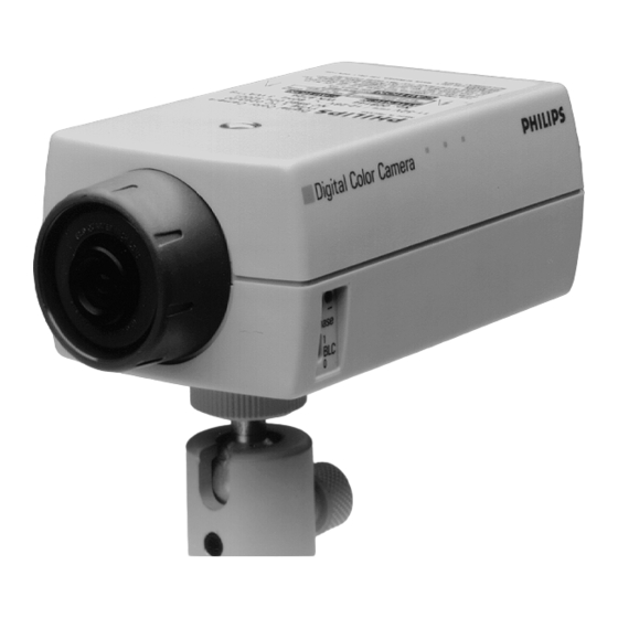
Summary of Contents for Philips LTC0240/10
- Page 1 Philips Communication & Security Systems Digital Color Cameras LTC 0240 LTC 0242 LTC 0243...
-
Page 2: Important Safeguards
IMPORTANT SAFEGUARDS 1. Read Instructions - All the safety and operating instructions should be read before the unit is operated. 2. Retain Instructions - The safety and operating instructions should be retained for future reference. 3. Heed Warnings - All warnings on the unit and in the operating instructions should be adhered to. - Page 3 12. Power-Cord Protection - Power-supply cords should be routed so that they are not likely to be walked on or pinched by items placed upon or against them, paying particular attention to cords and plugs, convenience receptacles, and the point where they exit from the appliance.
-
Page 4: Fcc & Ices Information
21. Lightning - For added protection of this unit during a lightning storm, or when it is left unattended and unused for long periods of time, unplug it from the wall outlet and disconnect the cable system. This will prevent damage to the unit due to lightning and power-line surges. - Page 5 Fig 1...
- Page 6 Fig 2...
- Page 7 mm (inches) Fig 3...
-
Page 8: Safety Precautions
Safety Precautions CAUTION: TO REDUCE THE RISK OF ELECTRICAL SHOCK, DO NOT OPEN COVERS. NO USER SERVICEABLE PARTS INSIDE. REFER SERVICING TO QUALIFIED SERVICE PERSONNEL. This label may appear on the bottom of the unit due to space limitations. The lightning flash with an arrowhead symbol, within an equilat- eral triangle, is intended to alert the user to the presence of un- insulated "dangerous voltage"... - Page 9 Digital Color Camera WARNING Before applying the power supply, check that the voltage indication on the equipment corresponds with the local supply voltage. These cameras have been designed for indoor CCTV surveillance applica- tions. LTC 024x Camera Versions Low Voltage d.c.* Low Voltage a.c.* Mains Voltage (Class II) PAL 625 lines 50 Hz...
- Page 10 UK - 3-pin mains connector When fitting a UK 3-pin mains connector the wires are connected as fol- lows: Blue Brown Lens LTC 0240 LTC 0242 LTC 0243 Lens connector - LTC 0240 only (Fig. 1 - B) The 4-pin lens socket located on the back is connected as follows: Adjustments MAINS-/LINE-LOCK (Fig.
- Page 11 Backlight Compensation BLC OFF - The camera Automatic Light Control (ALC) responds to the average content of the entire video picture. BLC ON - The camera ALC responds pre- dominantly to the center of the picture, shown by the diagram. If an object of interest falls inside the BLC area, its visibility will remain relatively constant even if the background illu- mination varies.
- Page 12 Technical Specification Sensor TV Standard Resolution Lens LTC 0240 LTC 0242 LTC 0243 Sensitivity Shutter speed Auto white balance Video output Video connector Power consumption Mains-/Line- Lock Material Dimensions Weight Environmental Temperature range: Operating: Storage Air pressure Relative humidity Shock Vibration Electro Magnetic Compatibility EMC requirement...
- Page 13 3922 988 85113 98-35 © 1998 Philips Electronics N.V. Data subject to change without notice...


Need help?
Do you have a question about the LTC0240/10 and is the answer not in the manual?
Questions and answers