Table of Contents
Advertisement
Colour Observation Camera
Table of contents
Introduction.............................................................................................................. 4
Connection and operation facilities ...................................................................... 5
Installation .............................................................................................................. 5
Camera position
Using a different lens .............................................................................................. 9
System cable .......................................................................................................... 10
Tips for maintenance ............................................................................................ 10
Introduction
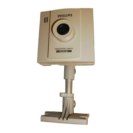
This camera is especially designed for the colour Philips Observation Systems. It combines a high sensitivity
sensor with advanced digital signal processing, resulting in a high quality camera with excellent performance
under even difficult circumstances. The camera has a standard camera mount allowing installation on, for
example, a tripod or wall bracket.
Camera accessories:
The following camera accessories are available:
• Protective camera housing for protection against dust and theft
• Weather proof housing for outside use
• Extension system cables
• Mains power adapter for providing additional power to the camera at large distances
Read these instructions, before taking your system in operation.
4
English
Page
Advertisement
Table of Contents

Summary of Contents for Philips VCM7A79/00T
-
Page 1: Table Of Contents
Tips for maintenance ... 10 Introduction This camera is especially designed for the colour Philips Observation Systems. It combines a high sensitivity sensor with advanced digital signal processing, resulting in a high quality camera with excellent performance under even difficult circumstances. The camera has a standard camera mount allowing installation on, for example, a tripod or wall bracket. -
Page 2: Connection And Operation Facilities
Connection and operation facilities Focus adjustment ring Back-focus adjustment ring Camera sound on/off Auto-iris socket Cable length compensation selector System cable socket External supply socket Installation This chapter describes the installation of the camera. For more detailed information about the installation and operation of the system monitor you should consult the monitor manuals. - Page 3 Installation 1. Take the camera, system cable and monitor to the area you want to observe (with the monitor on site, you can check whether the camera covers the required area). Remark: For outdoor use protective camera housing has to be used to protect the camera from rain and snow.
- Page 4 7. Check on the monitor whether the camera covers the required area (The best results are obtained when the camera is pointed slightly downwards and is not looking into a bright light source). Adjust focus if necessary. 8. Fasten the wall bracket (1) to the wall, or another even and firm surface.
-
Page 5: Focus Adjustment
Focus adjustment • Adjust the focus ring of the camera lens to obtain optimal image sharpness. Remark: If still no sharp object image is obtained, you should adjust the back-focus of the camera. Back-focus adjustment Caution: Back-focus adjustment is only necessary when no sharp object image is obtained with the focus adjustment ring. -
Page 6: Using A Different Lens
Using a different lens The CS-mount of the camera allows you to use other lenses. The field of view (= covered area) of an 8mm lens is half of the field of view of the 4mm lens (see figure below). The auto-iris lenses are recommended when the camera is used in environments with variable light conditions (eg. -
Page 7: System Cable
System Cable For the interconnections between the system monitor and camera 25m/75ft system cable is supplied. For an optimum picture and sound quality you should always use 4-wire dual twisted- pair cable when extending the connection. The max. allowed cable length is 300m/900ft. -
Page 8: Technical Specifications
Technical specifications Pick-up element Pixel elements 5 Resolution Gain control Lens Iris Light sensitivity Scene illumination Signal to noise ratio White balance TTL System connector (output) Microphone • Frequency range Synchronisation Power supply Power consumption System-cable length Dimensions Weight Connectors •...


Need help?
Do you have a question about the VCM7A79/00T and is the answer not in the manual?
Questions and answers