Table of Contents
Advertisement
Quick Links
Advertisement
Table of Contents

Subscribe to Our Youtube Channel
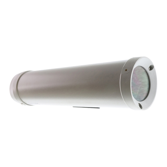
Summary of Contents for Philips LTC 9483/00
- Page 1 Unity ™ Line Housings LTC 9480, LTC 9483 Series, LTC 9488 Series...
-
Page 2: Important Safeguards
IMPORTANT SAFEGUARDS 1. Read Instructions - All the safety and operating instructions should be read before the unit is operated. 2. Retain Instructions - The safety and operating instructions should be retained for future reference. 3. Heed Warnings - All warnings on the unit and in the operating instructions should be adhered to. -
Page 3: Safety Precautions
SAFETY PRECAUTIONS CAUTION: TO REDUCE THE RISK OF ELECTRICAL SHOCK, DO NOT OPEN COVERS. NO USER SERVICEABLE PARTS INSIDE. REFER SERVICING TO QUALIFIED SERVICE PERSONNEL. This label may appear on the bottom of the unit due to space limitations. The lightning flash with an arrowhead symbol within an equilateral triangle is intended to alert the user to the presence of uninsulated "dangerous voltage"... -
Page 4: Table Of Contents
If an item appears to have been damaged in shipment, replace it properly in its carton and notify the shipper. If any items are missing, notify your Philips Communication & Security System Inc. Sales Representative or Customer Service. The shipping carton is the safest container in which the unit may be transported. -
Page 5: Model Designation
Model Designation Model Preinstalled Voltage/ Heater or Power Heater/Blower Indoor Units LTC 9480/00 24/0- Outdoor Units LTC 9483/00 ----- LTC 9488/00 ----- LTC 9483/20 Heater 24/23 LTC 9483/21 Heater/Blower 24/25 LTC 9483/50 Heater 230/23 LTC 9483/60 Heater 115/23 LTC 9483/61 Heater/Blower 115/28 LTC 9488/20... -
Page 6: Cover Removal
Cover Removal 1. Loosen the top two screws on the rear of the housing. These screws are captive and will not come out all the way. Do not remove the bottom two screws. See Figure 1. Figure 1: Loosening Captive Screws 2. -
Page 7: Camera/Lens Wiring
Mounting LTC 0330/x1, LTC 0350/x1, LTC 0430/x1, and LTC 0450/x1 fixed lens cameras in LTC 9480, LTC 9483 Series Housings 3c. Remove the mounting block from the camera by removing the two small screws that attach the foot to the camera. Use a small straight blade screw driver to remove these screws. - Page 8 Figure 7: Feed-through Wiring 2. Screw the two 3/8-in NPT fittings into the foot of the housing. 3. Pull the cabling through the fittings and into the housing. Tighten the fitting to 4.0 N-m to 4.5 N-m (35 in-lb to 40 in-lb).
-
Page 9: Video Coax Connection
Failure to do so will allow water to enter and damage all electronic parts. Be sure to securely tighten all fittings to ensure a liquid-tight seal. Failure to do so could allow water to enter the housing and damage the camera and lens. 5. -
Page 10: Fuse Replacement
Figure 10: Reinstalling the Cover 3. As the cover nears the rear cap, make sure the captive screws in the back are not blocking the cover from engaging into the rear cap. 4. Screw the two rear captive screws into the housing. 6.13 Fuse Replacement 1. -
Page 11: Exploded View
EXPLODED VIEW Parts List Drawing Number Part Description 315 3369 020 24 VAC Heater Kit (LTC 9483) 315 3369 050 230 VAC Heater Kit (LTC 9483) 315 3369 060 115 VAC Heater Kit (LTC 9483) 315 3368 020 24 VAC Heater Kit (LTC 9488) 315 3368 050 230 VAC Heater Kit (LTC 9488) 315 3368 060... - Page 12 Ó 3935 890 17812 99-41 Ó Printed In U.S.A. All Rights Reserved. Philips Philips Electronics N.V. Data subject to change without notice 1999 Philips Electronics N.V. 1999 Philips Communications & Security Systems Inc. Ò is a registered trademark of...


Need help?
Do you have a question about the LTC 9483/00 and is the answer not in the manual?
Questions and answers