
Related Manuals for Kikusui PLZ-4W Series


Summary of Contents for Kikusui PLZ-4W Series
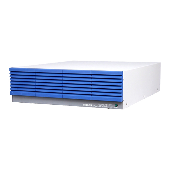
- Page 1 Part No. Z1-002-802, IB004183 Jun. 2008 OPERATION MANUAL ELECTRONIC LOAD PLZ-4W Series PLZ2004 WB...
- Page 2 If you fi nd an y incorrectly arranged or missing pages in this manual, the y will be replaced. If the manual gets lost or soiled, a ne w cop y can be pro vided for a fee. In either case, please contact Kikusui distrib utor/ agent, and pro vide the “Kikusui P art No.
- Page 3 Saf ety Symbols For the saf e use and saf e maintenance of this pr oduct, the f ollo wing symbols are used thr oughout this man ual and on the pr oduct. Under - stand the meanings of the symbols and obser ve the instructions the y indicate (the c hoice of symbols used depends on the pr oducts).
-
Page 4: Safety Precautions
Saf ety Precautions The f ollo wing saf ety precautions m ust be obser ved to a v oid fi re hazard, electrical shock, accidents, and other failures. Keep them in mind and make sure that all of them are observed properly. Users •... - Page 5 • To maintain performance and safe operation of the product, it is recommended that periodic maintenance, checking, cleaning, and calibration be performed. Service • Internal service is to be done by Kikusui service engineers. If the product must be adjusted or repaired, contact Kikusui distributor/agent. PLZ2004WB...
-
Page 6: Arrangement Of This Manual
Arrangement of this Manual This Operation Manual is made up of the following sections. Chapter 1 General Information This chapter gives an overview and describes the features of the PLZ2004WB. Chapter 2 Installation and Preparation This chapter describes the procedures of unpacking and preparation of the PLZ2004WB before use. -
Page 7: Table Of Contents
Contents Safety Symbols ____________________________________________ I Safety Precautions ________________________________________ II Arrangement of this Manual ________________________________ IV Chapter 1 General Information Chapter 2 Installation and Preparation Checking the Package Contents - - - - - - - - - - - - - - - - - - - - - - - - - - - - - 2-1 Precautions Concerning Installation Location - - - - - - - - - - - - - - - - - - - 2-2 Precautions When Moving the Unit... - Page 8 VI Contents PLZ2004W...
-
Page 9: Chapter 1 General Information
Chapter 1 General Information This chapter gives an overview and describes the features of the PLZ2004WB. About This Manual This operation manual describes the PLZ2004WB Load Booster. The PLZ2004WB is used in combination with the PLZ1004W Electronic Load. This manual mainly covers the handling precautions of the PLZ2004WB and the connection to the PLZ1004W. - Page 10 Rack mount bracket The following rack mounting brackets are available. • KRB3-TOS (for inch-rack EIA standard) • KRB150-TOS (for milli rack JIS standard) For details, contact Kikusui distributor/agent. KRB3-TOS KRB150-TOS Unit: mm Fig.1-1 Rack mount bracket installation example 1-2 General Information...
-
Page 11: Chapter 2 Installation And Preparation
When you receive the product, check that all accessories are included and that the product and accessories have not been damaged during transportation. If any of the accessories are damaged or missing, contact Kikusui distributor/agent. NOTE • It is recommended that all packing materials be saved, in case the product needs to be transported at a later date. -
Page 12: Precautions Concerning Installation Location
fire. However, operation in such environments may be possible through alteration. If you wish to use the unit in such environments, consult Kikusui distributor/agent. ■ Do not place the unit in a dusty location. Accumulation of dust can lead to electric shock or fire. -
Page 13: Precautions When Moving The Unit
■ Do not use the unit in a location subject to strong magnetic or electric fields. The unit may malfunction and cause electric shock or fire. ■ Do not use the unit near highly sensitive measuring instru- ments or transceivers. The noise generated by the unit may affect them ■... -
Page 14: Connecting The Power Cord
VAC to 250 VAC and 47 Hz to 63 Hz, respectively. Connect the power cord to the AC INPUT connector on the rear panel. Use a power cord specified by Kikusui or one that has been selected by a qual- ified engineer. -
Page 15: Grounding
Grounding WARNING • Electric shock may occur, if proper grounding is not furnished. • This product is designed as a Class I equipment (equipment furnished with electric shock protection through protective grounding in addition to the basic insulation). Be sure to connect the protective ground terminal to an appropriate earth ground. -
Page 16: Parallel Connection
Parallel Connection To carry out parallel operation, you must connect signal wires used to connect to the master unit and the load cable used to connect to the equipment under test. Use the optional flat cable for the signal wire. For details, see “Control flat cables” in chapter 1, “General Information.”... -
Page 17: Connecting The Signal Cables
CAUTION • Be sure to use the load input terminals on the rear panel on the master unit. Do not connect other equipment to the load input terminal on the front panel. • Improper connection of the J1 and J2 connectors can damage the PLZ2004WB. - Page 18 Connection to the load input terminal The load input terminal on the PLZ1004W (master unit) is not designed for large currents as in the load input terminal of the load booster. As shown in Fig. 2-5, separate the load wire from the equipment under test for the master unit and the load booster.
- Page 19 Wrap the auxiliary band between the rear panel and the bolt. The auxiliary band prevents the load input terminal cover from sliding. Wrap the band tightly to fill up the space between the panel and the bolt. Auxiliary band Wrap the load input terminal cover Load input terminal cover over the auxiliary band.
-
Page 20: Setting The Master Unit
Setting the Master Unit Turn on the power to the master unit. The power to the load booster is in sync with the power to the master unit. Select the menu setup. Press the MENU (SHIFT+SET/VSET) key. The menu appears. Select Configuration Press the CURSOR key several times until Configuration is high-... -
Page 21: Chapter 3 Names And Functions Of Parts
Chapter 3 Names and Functions of Parts This chapter describes the names and functions of switches, displays, connectors, and other parts of the front panel and rear panel. Front Panel 2000W ELECTRONIC LOAD PLZ2004WB 150V 400A POWER Fig.3-1 PLZ2004WB Front Panel [1] POWER lamp Illuminates when the power switch of the master unit is on when the load booster is connected in parallel with the master unit. -
Page 22: Rear Panel
Rear Panel WARNING TO AVOID ELECTRIC SHOCK, THE POWER CORD PROTECTIVE GROUNDING CONDUCTOR MUST BE CONNECTED TO GROUND. DO NOT REMOVE COVERS, REFER SERVICING TO QUALIFIED PERSONNEL. AC INPUT 100-240V 47-63Hz 200VA MAX Fig. 3-2 PLZ2004WB Rear panel [3] J1 and J2 connectors Connector used to connect the control signal using the optional flat cable. -
Page 23: Chapter 4 Maintenance
Chapter 4 Maintenance This chapter describes maintenance and calibration of the PLZ2004WB. WARNING • Possible electric shock. May lead to death or injury. Do not remove the external cover. Cleaning WARNING • Possible electric shock. May lead to death or injury. Be sure to unplug the power cord plug. - Page 24 Cleaning procedure Remove the louver from the panel by placing a finger on the 2nd level of the louver and pulling down the 1st level while pulling it toward you. If the louver does not come off easily, pressing down the top level of the louver will ease the work.
-
Page 25: Inspection
• Breaks in the insulation coating may cause electric shock. If a break is found, stop using it immediately. To purchase accessories, contact Kikusui distributor/agent. Calibration The PLZ2004WB is shipped from the factory after carrying out a strict calibration. - Page 26 4-4 Maintenance PLZ2004WB...
-
Page 27: Chapter 5 Specifications
Chapter 5 Specifications This chapter describes the electrical and mechanical specifications of the PLZ2004WB. Electrical Specifications Unless specified otherwise, the specifications are for the following settings and con- ditions. • Warm-up period: 30 minutes (with current flowing) • Ambient temperature: 23 °C ± 5 °C •... - Page 28 Input/output signal J1 connector 20-pin MIL connector J2 connector 20-pin MIL connector Used to connect to the master unit Used to connect to load booster n (or load booster) 1 NC 1 NC 2 NC 2 NC 3 NC 3 NC 4 SUM I MON Connect to SUM I MON of the J2 4 SUM I MON...
-
Page 29: General Specifications
General Specifications Environment Operating temperature and Temperature: 0 °C to 40 °C humidity range Humidity: 20% to 85% RH (no condensation) Storage temperature and Temperature: -25 °C to 70 °C humidity range Humidity: Less than or equal to 90% (no condensation) Input line voltage range 100 VAC to 240 VAC (90 VAC to 250 V) single phase, continuous Input frequency range... -
Page 30: Dimensions
Dimensions MAX440 MAX600 429.5 Unit: mm Fig.5-1 PLZ2004WB outline drawing 5-4 Specifications PLZ2004WB... -
Page 31: Index I
Inde x AC INPUT connector Overvoltage Category II accessories air intake air outlet POWER lamp calibration rack mount bracket Class I equipment cleaning control flat cables transportation DC INPUT dust filter earth ground grounding inspection installation J1 connector J2 connector load input terminal louver moving the unit...
Need help?
Do you have a question about the PLZ-4W Series and is the answer not in the manual?
Questions and answers