Table of Contents
Advertisement
Twin Rotor Mimo System
INSTALLATION AND COMMISSIONING
33-007-0M5
Feedback
Feedback Instruments Ltd, Park Road, Crowborough, E. Sussex, TN6 2QR, UK.
Telephone: +44 (0) 1892 653322,
Fax: +44 (0) 1892 663719.
email: feedback@fdbk.demon.co.uk
World Wide Web Homepage: http://www.fbk.com
Manual: 33-007-0M5 Ed01 980930
Printed in England by Fl Ltd, Crowborough
Feedback Part No. 1160–330070M5
Advertisement
Table of Contents

Related Manuals for feedback Twin Rotor Mimo System

Summary of Contents for feedback Twin Rotor Mimo System
- Page 1 Twin Rotor Mimo System INSTALLATION AND COMMISSIONING 33-007-0M5 Feedback Feedback Instruments Ltd, Park Road, Crowborough, E. Sussex, TN6 2QR, UK. Telephone: +44 (0) 1892 653322, Fax: +44 (0) 1892 663719. email: feedback@fdbk.demon.co.uk World Wide Web Homepage: http://www.fbk.com Manual: 33-007-0M5 Ed01 980930 Printed in England by Fl Ltd, Crowborough Feedback Part No.
- Page 2 Notes TOC 2...
- Page 3 While we provide the fullest possible user information relating to the proper use of this equipment, if there is any doubt whatsoever about any aspect, the user should contact the Product Safety Officer at Feedback Instruments Limited, Crowborough. This equipment should not be used by inexperienced users unless they are under supervision.
- Page 4 Should this equipment be used outside the classroom, laboratory study area or similar such place for which it is designed and sold then Feedback Instruments Ltd hereby states that conformity with the protection requirements of the European Community Electromagnetic Compatibility Directive (89/336/EEC) may be invalidated and could lead to prosecution.
-
Page 5: Table Of Contents
TWIN ROTOR MIMO SYSTEM Installation and Commissioning Contents TABLE OF CONTENTS INTRODUCTION 1.1 Required Equipment 1.2 Feedback Ltd supplied items MECHANICAL ASSEMBLY SWITCH AND JUMPER SETTINGS FOR THE PCL-812 CARD 3.1 Switch settings - 16 bit board 3.2 Jumper Settings 3.3 Switch SW1 settings for 8 bit full length PCL - 812 board... - Page 6 TWIN ROTOR MIMO SYSTEM 33-007-0 Contents Installation and Commissioning Notes TOC 2 33-007-0...
-
Page 7: Introduction
Introduction 1. Introduction This manual contains a description of the components of the Twin Rotor MIMO System ( TRMS ), and assembly and test procedures. It is intended to provide the means for validating the correct operation of the system, before proceeding to the more advanced functions and demonstrations using control software and MATLAB / SIMULINK. -
Page 8: Feedback Ltd Supplied Items
TWIN ROTOR MIMO SYSTEM Introduction Installation and Commissioning 1.2 FEEDBACK LTD SUPPLIED ITEMS The following items are supplied by Feedback under the following product codes 33-220 Twin Rotor Mechanical Unit with remote On/Off switch 33-945 Twin Rotor MIMO System Software pack including Advantech card... -
Page 9: Mechanical Assembly
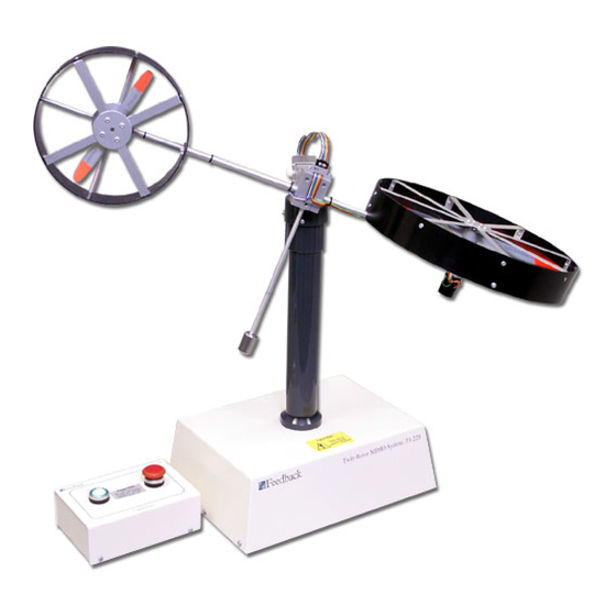
CHAPTER 2 TWIN ROTOR MIMO SYSTEM Installation and Commissioning Mechanical Assembly 2. Mechanical Assembly The MIMO Unit is dis-assembled for transit. Follow the instructions below for re-assembly and refer to Fig. 2.1. Mounting for Tower 3 x M4 screws either end... - Page 10 CHAPTER 2 TWIN ROTOR MIMO SYSTEM Mechanical Assembly Installation and Commissioning Figure 2.2 below shows the complete TRMS/MIMO assembly. 80 mm This angle ~ 28° Fig. 2.2: The complete TRMS/MIMO Assembly Note: The MIMO has two degrees of freedom - the rotors can rotate about a vertical and a horizontal axis.
-
Page 11: Switch And Jumper Settings For The Pcl-812 Card
CHAPTER 3 TWIN ROTOR MIMO SYSTEM Installation and Commissioning PCL – 812 Card Settings 3. Switch And Jumper Settings for the PCL-812 Card The PCL-812 contains components which can be damaged by static electricity. Before removing the PCL-812 board from its conductive packaging, touch your hand on a grounded metal object such as the case of your PC. -
Page 12: Switch Settings - 16 Bit Board
CHAPTER 3 TWIN ROTOR MIMO SYSTEM PCL – 812 Card Settings Installation and Commissioning 3.1 SWITCH SETTINGS - 16 BIT BOARD Switch SW1 controls the base address for I/O transfer (switches 1-6), and the CPU wait states (Switches 7-8). They should be set as follows. -
Page 13: Jumper Settings
CHAPTER 3 TWIN ROTOR MIMO SYSTEM Installation and Commissioning PCL – 812 Card Settings 3.2 JUMPER SETTINGS The Jumpers on the PCL-812 board should be set in the positions indicated below. JP1 - Trigger Source Selection JP2 - Counter Input Clock Selection... -
Page 14: Switch Sw1 Settings For 8 Bit Full Length Pcl - 812 Board
CHAPTER 3 TWIN ROTOR MIMO SYSTEM PCL – 812 Card Settings Installation and Commissioning JP8, JP9 - D/A Internal Reference, A/D Maximum Input Voltage Selection Depending on the specification and configuration of your PC you may need to change the Base Address and Wait State settings. -
Page 15: Installation Of The Pcl-812 Card And Cables
It is important to determine the addresses of any such cards as your Twin Rotor MIMO System will not function correctly if there is another card using all, or part of, the address space assigned to the PCL-812PG interface card. - Page 16 Installation and Commissioning Following the installation of the interface card into your PC, you are now ready to close the PC case and connect the ribbon cables to the 33-220 Twin Rotor MIMO System. Refer to Fig 6.2 below for details.
- Page 17 CHAPTER 4 TWIN ROTOR MIMO SYSTEM Installation and Commissioning PCL-812 Card Installation Software Installation Install the Commissioning / Test software as described in the next Chapter of this manual (Chapter 5). It is important that the area of operation is free of obstruction and that users and observers are warned to keep clear of the immediate vicinity of the system, as the twin rotors can build up a significant amount of momentum.
- Page 18 CHAPTER 4 TWIN ROTOR MIMO SYSTEM PCL-812 Card Installation Installation and Commissioning Notes 33-007-0...
-
Page 19: Commissioning And Test Software
CHAPTER 5 TWIN ROTOR MIMO SYSTEM Installation and Commissioning Commissioning and Test Software 5. Commissioning and Test Software 5.1 STARTING THE SOFTWARE Commissioning / Test software is supplied to check the operation of the Twin Rotor MIMO System, before using the MATLAB driven control software. - Page 20 CHAPTER 5 TWIN ROTOR MIMO SYSTEM Commissioning and Test Software Installation and Commissioning Click OK. The following screen appears, only if the card is not found at the factory default Base address of 544. Fig. 5.2: PCL-812 Base address Selection Use the mouse to select the base address of the PCL-812 interface card which has been set and checked in accordance with the procedure detailed in Chapter 3 of this manual.
-
Page 21: Description Of Screen Controls And Displays
Commissioning and Test Software 5.3 DESCRIPTION OF SCREEN CONTROLS AND DISPLAYS. This screen allows you to interact with the Twin Rotor MIMO System, change the speeds of the motors on the rotors by changing the applied voltages, and display the outputs from the two rotary encoders, which measure angular displacements about a horizontal and a vertical axis. - Page 22 CHAPTER 5 TWIN ROTOR MIMO SYSTEM Commissioning and Test Software Installation and Commissioning 2.6 v Shows the output voltages from the vertical and horizontal tachogenerators. 1.8 v HOT KEYS Note that as an alternative to using the mouse, the functions displayed on the screen can be activated by typing ALT + the highlighted letter displayed in reverse video on the screen.
-
Page 23: Test Sequence
CHAPTER 6 TWIN ROTOR MIMO SYSTEM Installation and Commissioning Test Sequence 6. Test Sequence When you have completed the installation of the system, execute the following test sequence to ensure that the system is functioning properly. • Start MIMOTST commissioning software, and check correct base address •... - Page 24 CHAPTER 6 TWIN ROTOR MIMO SYSTEM Test Sequence Installation and Commissioning ACTION RESULT 7. Turn the horizontal axis locking screw to stop rotation about the horizontal axis. 8. Drag the slider on the The horizontal motion motor starts to rotate horizontal motion motor clockwise viewed from the front.
Need help?
Do you have a question about the Twin Rotor Mimo System and is the answer not in the manual?
Questions and answers