Advertisement
Quick Links
MARKING OF STRIKE POSITION
1
'X ' mm
Door
Frame
Mark Door latch
front face on frame
(Line 1).
To enable the Electric strike to be located in the door frame, first
mark the position of the Door Latch front face on the door frame
with the door in the closed position, ('X ' mm).
Mark where centre of latch meets door frame:
- For new installations, mark frame where front of latch touches
the door frame at the midpoint of the latch bolt.
- For retrofit installations, remove existing strike plate and ensure
that latch fits into and is centred in existing hole.
3
24mm
Using the template as a guide, mortice out the door frame to the
required size.
Countersink holes in metal frame to accept screws.
For wider framed doors an Extension Lip may be required. Refer
to over leaf for sizes and part numbers.
ES9000 SERIES ELECTRIC STRIKE
INSTALLATION INSTRUCTIONS
'X ' mm
Mark centre of Door
latch on frame
(Line 2).
2
L i n e
Latch
Frame
Door
MORTICING REBATE
2
L A T E
E M P
S T IC
O N T
K -
T P 0
0 0
S c ri
b e
o u tl in
e
22mm
2
L in e
22mm
Hole 'A'
Metal Door Frame
Peel backing off adhesive template and centrally locate in the
marked position, lining up both the mark for the door latch front
face (Line 1) and the centre mark of the latch (Line 2).
For a metal door drill two Ø5mm holes (A) 22mm above and
below the 'x' mark on the template, for a timber door drill
two Ø3mm holes (B).
Ensure secondary bolt is not within strike cavity.
CHANGING MODE OF LOCK OPERATION
4
Power to Lock (PTL) to Power to Open (PTO) conversion.
Loosen mode change screw two turns with the supplied
2mm hex key.
Factory default setting is Power to Lock (PTL)
Move to required position as shown:
Power to Open Fig. A
Power to Lock Fig. B
Retighten mode change screw firmly.
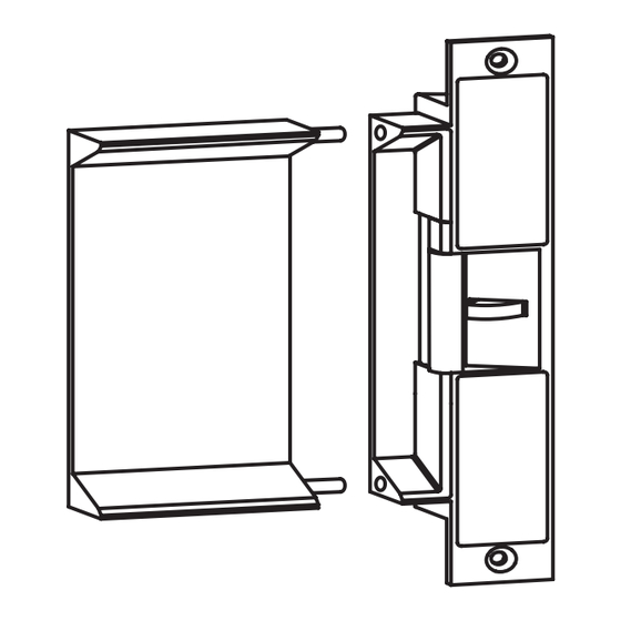
POSITIONING OF STRIKE
L A T E
S T IC
E M P
O N T
K -
T P 0
0 0
S c ri
b e
o u tl in
e
Strike
cavity
Hole 'B'
Timber Door Frame
A - Power to Open
(Fail-Secure)
Configuration
B - Power to Lock
(Fail-Safe)
Configuration
R
Advertisement

Related Manuals for Lockwood PADDE TRIMEC PRE-LOAD ES9000 Series


Summary of Contents for Lockwood PADDE TRIMEC PRE-LOAD ES9000 Series
- Page 1 ES9000 SERIES ELECTRIC STRIKE INSTALLATION INSTRUCTIONS MARKING OF STRIKE POSITION POSITIONING OF STRIKE 'X ' mm L A T E Mark centre of Door L A T E E M P S T IC S T IC E M P O N T O N T T P 0...
- Page 2 ELECTRICAL SPECIFICATION CAUTION! Incorrect supply voltage may cause damage not covered by warranty. Solenoid Monitor Wiring: Please check supply voltage with a suitable meter to ensure it is within 10-30V DC. Unpowered Current required is 250mA @12V DC to 130mA @ 24V DC N.O.
Need help?
Do you have a question about the PADDE TRIMEC PRE-LOAD ES9000 Series and is the answer not in the manual?
Questions and answers