Advertisement
Quick Links
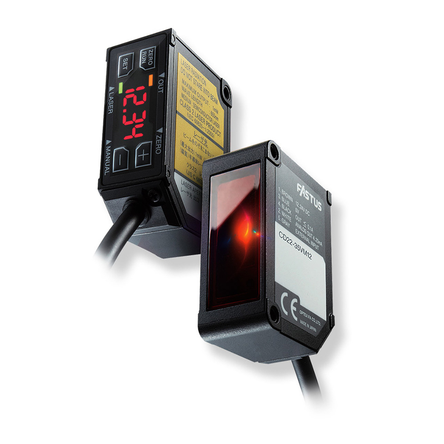
Displacement sensor
CD22 Series
CD22-15
CD22M-15
CD22-35
CD22M-15
CD22-100
CD22M-100
Instruction manual
- Thank you for purchasing CD22 series. We hope you are satisfi ed with its performance.
- Please read this manual carefully and keep it for future reference.
Indicates a possible hazard that may result in death, serious
injury, WARNINGS or serious property damage if the product is
used without observing the stated instructions.
Warning Mandatory Requirements
● The light source of this product applies the visible light semiconductor laser. Do not
allow the laser beam to enter an eye, either directly or refl ected from refl ective object. If
the laser beam enters an eye, it may cause blindness.
● This product is not an explosion proof construction. Do not use the product under fl am-
mable , explosive gas or liquid environment.
● Do not disassemble or modify the product since it is not designed to automatically stop
the laser emission when open. Disassembling or modifying at customer's end it may
cause personal injury, fi re or electric shock.
●Use of controls or adjustments or performance of procedures other than those specifi ed
herein may result in hazardous radiation exposure.
Warning Safety Precautions
● It is dangerous to wire or attach/remove the connector while the power is on. Make sure
to turn off the power before operation.
● Installing in the following places may result in malfunction:
1. A dusty or steamy place
2. A place generating corrosive gas
3. A place directly receiving scattering water or oil.
4. A place suff ered from heavy vibration or impact.
● The product is not designed for outdoor use.
● Do not use the sensor in a transient state at power on (Approx. 15min. Warm up period)
● Do not wire with the high voltage cable or the power lines. Failure to do this will cause
malfunction by induction or damage.
● Do not use the product in water.
● Operate within the rated range.
● Wipe
off dirt on the emitting/receiving parts to maintain correct detection. Also, avoid
direct impact on the product.
● Don't bend the cable when the temperature of the cable or atmosphere is below freezing.
Precautions for using laser
● Regulations in the USA
When exporting laser devices to the USA, the USA laser control, FDA
(Food and Drug Administration) is applied. This product has been already
reported to CDRH (Center for Devices and Radiological Health). For
details, contact our customer service.
Laser diode
Wave length:655nm, Max output:10mW,//9 degree type.
Bundled goods in the box
Please confi rm following goods bundled in the box.
・CD22 -
・This instruction manual
Displacement sensor
CD22 Series
CD22-15
CD22M-15
CD22-100
CD22-35
CD22M-100
CD22M-15
Instruction manual
- Thank you for purchasing CD22 series. We hope you are satisfi ed with its performance.
- Please read this manual carefully and keep it for future reference.
Indicates a possible hazard that may result in death, serious
injury, WARNINGS or serious property damage if the product is
used without observing the stated instructions.
Warning Mandatory Requirements
allow the laser beam to enter an eye, either directly or refl ected from refl ective object. If
● The light source of this product applies the visible light semiconductor laser. Do not
● This product is not an explosion proof construction. Do not use the product under fl am-
the laser beam enters an eye, it may cause blindness.
● Do not disassemble or modify the product since it is not designed to automatically stop
mable , explosive gas or liquid environment.
the laser emission when open. Disassembling or modifying at customer's end it may
cause personal injury, fi re or electric shock.
herein may result in hazardous radiation exposure.
●Use of controls or adjustments or performance of procedures other than those specifi ed
Warning Safety Precautions
to turn off the power before operation.
● It is dangerous to wire or attach/remove the connector while the power is on. Make sure
● Installing in the following places may result in malfunction:
1. A dusty or steamy place
3. A place directly receiving scattering water or oil.
2. A place generating corrosive gas
● The product is not designed for outdoor use.
4. A place suff ered from heavy vibration or impact.
● Do not use the sensor in a transient state at power on (Approx. 15min. Warm up period)
● Do not wire with the high voltage cable or the power lines. Failure to do this will cause
malfunction by induction or damage.
● Do not use the product in water.
● Operate within the rated range.
direct impact on the product.
● Wipe off dirt on the emitting/receiving parts to maintain correct detection. Also, avoid
Precautions for using laser
When exporting laser devices to the USA, the USA laser control, FDA
● Regulations in the USA
(Food and Drug Administration) is applied. This product has been already
reported to CDRH (Center for Devices and Radiological Health). For
details, contact our customer service.
Laser diode
Wave length:655nm, Max output:10mW,//9 degree type.
Bundled goods in the box
Please confi rm following goods bundled in the box.
・CD22 -
・This instruction manual
Measurement mode
CD22 has 3 measurement mode. The mode is chosen by "Teach mode".
Following output shows its ON/OFF status as "Light ON
Output can be reversed by setting "Output polarity
Acti
L on
".
".
● 1 point Teaching
will be ON.
Teaching is done at a position. When the measurement distance is closer than that position, the output
FAr
hYSt
● 2 point Teaching
put will be ON.
Teaching is done at 2 positions. While the measurement distance is between those positions, the out-
FAr
nEAr
hYSt
hYSt
● FGS2
teresis
Teaching is done at a position. When the measurement distance is closer than the distance set by "Hys-
toL
"from the position that Teaching is done, the output will be ON. It works as FGS sensor.
FGS2
toL
hYSt
hYSt
Analog Output
Analog Current or Analog Voltage type outputs Analog output according to the measurement dis-
The distance range for Analog output is set in Teaching mode or Setup mode.
tance.
approx. 24mA
(approx. 15V)
4nA
20nA
0U
10U
● Default value of each Analog output type
4nA
Current ( Voltage)
(
0U
)
- 5.000
CD22 -15
- 15.000
CD22 -35
20nA
10U
(
)
5.000
15.000
External Input
Multiple function can be set at external input. When it's set as "Teaching" or "Zero reset", The function
varies by input period as follows.
■ Teaching
input period (sec.)
What to teach (Teaching current position)
0 to 0.5 sec.
0.5 to 1.5 sec.
Do nothing
Current output type : 4mA/ Voltage output type : 0V
2.5 to 3.5 sec.
1.5 to 2.5 sec.
Near side threshold
Current output type : 20mA/ Voltage output type 10V
over 4.5 sec.
3.5 to 4.5 sec.
FGS2 threshold
Far side threshold
■ Zero reset
0 to 1,999
input ( sampling )
Zero reset
Function
over 2,000
Release Zero reset
Ramco National - Optex FA Sensors
Measurement mode
CD22 has 3 measurement mode. The mode is chosen by "Teach mode".
・Laser WARNING label
・FDA Certifi cation label
・Screws
M3 × 15...2
Connection diagram
Specifi cations
Setup
● Part number legend
● Changing mode
■ NPN type
While it's "Teach mode", "Setup mode" or "Extension mode", you can change the mode
to "Measurement mode" by pressing "ZERO/RUN" button.
Brown : +V
DC 12~24V
10%
While it's "Setup mode" or "Extension mode", the LED "MANUAL" is lit.
3.3V
: External input
● Specifi cations per measurement range
number
Part
Aluminum housing
SUS housing
CD22M-15
CD22-15
CD22M-35
CD22-35
CD22M-100
CD22-100
: 0V / Analog GND
Measurement range
Center of measurement range
15mm
±5mm
±15mm
35mm
100mm
±50mm
* : M8 connector type doesn't have
Light source
Max. output: 390 µW
Red laser Diode (wave length 655nm)
※ 3
■ PNP type
class
Laser
IEC/JIS
Suffi x nul: CLASS 1 / 2: CLASS 2 (Laser Notice No.50)
Max. output: 1mW
Brown : +V
DC 12~24V
10%
Spot size
Linearity
※ 1
0.1% of F.S.
500 * 700µm
0.1% of F.S.
450 * 800µm
600 * 700µm
0.1% of F.S.
Repeatability
※ 2
1µm
6µm
20µm
: : External input
Temperature drift (typical value)
Sampling period
±0.02% / ℃ of F.S.
500µs / 1000µs / 2000µs / 4000µs / AUTO
±0.02% / ℃ of F.S.
±0.05% / ℃ of F.S.
● Changing parameters
You can choose and adjust the parameters by pressing "+" and "-" buttons.
External Input
Indicator
Laser OFF, Teaching, Sample & Hold, One shot, Zero reset
Output indicator: Orange / Mode indicator: Red
Laser indicator: Green / Zero reset indicator: Red
The mode will be changed to "Measurement mode" by pressing "ZERO/RUN" button.
Control Output
NPN/PNP max.100mA/DC30V ((Residual voltage 1.8 V max.)
: 0V / Analog GND
Current consumption
Protection circuit
Reverse connection protection, Over current protection
70mA max. including Analog output current
* : M8 connector type doesn't have
Protection category
Operating Temp./Humid.
-10 ~ 50℃ / 35 ~ 85% RH without freasing or condensation
IP67 including connection part
■ Pins confi guration
・ M12 type
・ M8 type
Storage Temp./Humid.
Ambient illuminance
Incandescent lamp: 3,000 lx max.
-20 ~ 60℃ / 35 ~ 85%/RH
( sensor side )
Shock resistence
Vibration resistence
10 ~ 55Hz, Double amplitude 1.5mm, X,Y,Z for 2 hours
500mm/s
2
( approx. 50G) X,Y,Z 3 times each
Weight
Material
Aluminum case with M12 connector : Approx. 60g including
Case: Aluminum/SUS316L, Front lens: PPSU, Display: PET
Teach mode
SUS case with M12 connector type : Approx. 90g including
300mm cable with connector
300mm cable with connector
Aluminum case with M8 connector : Approx. 40g
SUS case with M8 connector : Approx. 70g
NEnu
Dimensions
ply voltage: 24VDC, Sampling period: 500µs, Averaging: 64, Measuring distance: Center of the range, Testing
The specifi cations are based on the condition unless otherwise designated: Ambient temperature: 23℃ , Sup-
■ M12 type
[mm]
object: White ceramic
※ 1 Defi ned with center strength 1/e
2
(13.5%) at the center. There may be leak light other than the specifi ed
※ 3 for Laser Class 2 type ( Model : CD22-100AM122 , CD22-100VM122 , CD22-100A2 , CD22-100V2)
spot size. The sensor may be aff ected when there is a highly refl ective object close to the detection area.
※ 2 512 averaging time
NodE
1Pt
● Specifi cations per output
2Pt
FGS2
Part number
CD22 -
V
CD22 -
A
CD22 -
-485
Display
Type
Analog output range
Voltage output
0 ~ 10V
※ 1
4 ~ 20mA
Current output
RS-485 type
ー
FGS2
tch
Maximum load impedance
Output impedance
100
ー
300
ー
ー
ー
Power supply
※ 1
Please keep power supply voltage over 12.0V for Voltage output type
DC12-24V ±10%
※ 1
Functions of components
to get 0-10V analog output correctly.
nEAr
tch
M12 5pin
Connector
FAr
tch
・Laser label [reserve]
・FDA Certifi cation label
・Laser WARNING label
■ M8 type
● Control panel
Display
・Screws
M3 × 15...2
・Laser label [reserve]
Connector
M8 4pin
Setup mode
Miscellaneous function
Setup mode is chosen by pressing "SET" button from "Menu". (* means default value)
ALrN
cLNP
hoLD
10U
0. 1 23
hdct
0000
hoLD
0. 0 00
0U
0. 1 23
20nA
0. 1 23
hdct
4nA
0. 1 23
Loc
rESt
YES
Loc
nEAr
0. 1 23
no
diSP
on
uLoc
FAr
0. 1 23
oFF
Extension mode
FGS2
0. 1 23
Extension mode is chosen by pressing "+" and "-" buttons at a time for 1 second.
Parameters in Extension mode must be set correctly otherwise it might not work correctly.
Please use with default setting when changing parameters is not needed. ( " * " means default setting)
NodE
FGS2
1Pt
hYSt
0. 1 23
2Pt
NtoP
NAH
toL
0. 1 23
Pt5
Pt4
inp
oFF
Pt2
Pt3
LSr
Pt1
tch
S h
onE
thrE
bASE
2Ero
P400
Attention: Not to be Used for Personnel Protection.
P100
P200
Never use these products as sensing devices for personnel protection. Do-
ing so could lead to serious injury or death. These sensors do not include
SANP
1000
500
the self-checking redundant circuitry necessary to allow their use in per-
2000
tout
off
sonnel safety applications. A sensor failure or malfunction can cause either
an energized or de-energized sensor output condition.
CD22 -100
- 50.00
4000
100N
Please consult our distributors about safety products which meet OSHA,
50.00
Auto
SaNp
ANSI and IEC standards for personnel protection.
Acti
L on
D on
inct
1
any obligations on the part of manufacture.
● Specifi cations and equipment are subject to change without
256
● For more information, questions and comments regarding
products, please contact us below.
n_P
PnP
nPn
2Ero
0. 1 23
http://www.optex-fa.com/rohs_cn/
AUG
1
8
SEnS
Auto
N__6
91 Chudoji Awata-cho Shimogyo-ku Kyoto 600-8815 Japan
64
TEL : +81-(0)75-325-2920
FAX: +81-(0)75-325-2921
512
N__1
Website : http://www.optex-fa.com
Connection diagram
■ NPN type
■ PNP type
■ Pins confi guration
( sensor side )
Dimensions
■ M12 type
■ M8 type
www.Optex-Ramco.com
Setup mode
Setup mode is chosen by pressing "SET" button from "Menu". (* means default value)
Brown : +V
DC 12~24V
3.3V
: External input
: 0V / Analog GND
* : M8 connector type doesn't have
Brown : +V
DC 12~24V
: : External input
: 0V / Analog GND
* : M8 connector type doesn't have
・ M8 type
・ M12 type
M8 4pin
Connector
Got Questions? 1-800-280-6933
Spec
● Part nu
10%
● Specific
Center o
Measure
Light sou
Laser
class
10%
Spot size
Linearity
Repeata
Sampling
Tempera
Indicator
External
Control O
Current c
Protectio
Protectio
Operatin
Storage T
Ambient
Vibration
Shock re
Material
Weight
The spec
ply volta
object: W
[mm]
※ 1 De
spot size
※ 2 512
※ 3 for
● Specific
Display
Func
M12 5pin
Connector
● Control
Display
Part
numbe
Type
Analog
Maxim
Output
Power
※ 1
AL
Advertisement

Related Manuals for Fastus CD22 Series


Summary of Contents for Fastus CD22 Series
- Page 1 Spec Connection diagram ● Part nu Displacement sensor ■ NPN type CD22 Series Brown : +V DC 12~24V CD22-15 CD22M-15 CD22-35 CD22M-15 CD22-100 CD22M-100 3.3V Instruction manual : External input - Thank you for purchasing CD22 series. We hope you are satisfi ed with its performance. - Please read this manual carefully and keep it for future reference. ● Specific Indicates a possible hazard that may result in death, serious Part numbe injury, WARNINGS or serious property damage if the product is : 0V / Analog GND Center o used without observing the stated instructions.
- Page 2 Teach mode ■1: Setup mode ● Part number legend mEnu C D 2 2 To Setup mode _- _ _ _ _ _ _ _ _ _ Laser Class ● Nul : Class 1 ー ● 2 : Class 2 +...
- Page 3 Measurement mode Setup mode Miscellaneous function CD22 has 3 measurement mode. The mode is chosen by "Teach mode". Output can be reversed by setting "Output polarity Acti ". Setup mode is chosen by pressing "SET" button from "Menu". (* means default value) ALrN cLNP hoLD Following output shows its ON/OFF status as "Light ON L on ". ● 1 point Teaching Teaching is done at a position. When the measurement distance is closer than that position, the output hdct 0000 will be ON. 0. 1 23 hoLD 0 . 0 00 0. 1 23 hdct 20nA 0. 1 23 hYSt ● 2 point Teaching Teaching is done at 2 positions. While the measurement distance is between those positions, the out- 0. 1 23 put will be ON.
- Page 4 Miscellaneous function ALrN cLNP hoLD hdct 0000 0. 0 00 hoLD hdct rESt uLoc diSP Extension mode Extension mode is chosen by pressing "+" and "-" buttons at a time for 1 second. Parameters in Extension mode must be set correctly otherwise it might not work correctly. Please use with default setting when changing parameters is not needed. ( " * " means default setting) hYSt 0 . 1 23 NtoP thrE bASE P400 Attention: Not to be Used for Personnel Protection. P200 Never use these products as sensing devices for personnel protection. Do- P100 ing so could lead to serious injury or death. These sensors do not include the self-checking redundant circuitry necessary to allow their use in per- sonnel safety applications. A sensor failure or malfunction can cause either tout an energized or de-energized sensor output condition. 100N Please consult our distributors about safety products which meet OSHA, ANSI and IEC standards for personnel protection. SaNp inct http://www.optex-fa.com/rohs_cn/ ●...