Advertisement
Quick Links
For amazing technical/application support contact Ramco today!
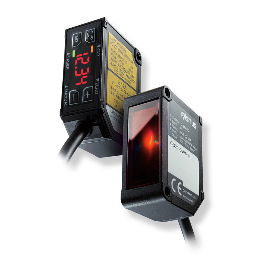
Displacement sensor
CD22 Series
Instruction manual
- Thank you for purchasing CD22 series. We hope you are satisfied with its performance.
- Please read this manual carefully and keep it for future reference.
Indicates a possible hazard that may result in death, serious
injury, WARNINGS or serious property damage if the product is
used without observing the stated instructions.
Warning
Mandatory Requirements
● The light source of this product applies the visible light semiconductor laser. Do not allow
the laser beam to enter an eye, either directly or refected from refrective object. If the laser
beam enters an eye, it may cause blindness.
●
mable , explosive gas or liquid environment.
● Do not disassemble or modify the product since it is not designed to automatically stop
the laser emission when open. Disassembling or modifying at customer's end it may
cause personal injury, fire or electric shock.
Use of controls or adjustments or performance of procedures other than those specified
●
herein may result in hazardous radiation exposure.
Warning
Safety Precautions
● It is dangerous to wire or attach/remove the connector while the power is on. Make sure
to turn off the power before operation.
● Installing in the following places may result in malfunction:
1. A dusty or steamy place
2. A place generating corrosive gas
3. A place directly receiving scattering water or oil.
4. A place suffered from heavy vibration or impact.
● The product is not designed for outdoor use.
● Do not use the sensor in a transient state at power on (Approx. 15min. Warm up period)
● Do not wire with the high voltage cable or the power lines. Failure to do this will cause
malfunction by induction or damage.
● Do not use the product in water.
● Operate within the rated range.
● Wipe off dirt on the emitting/receiving parts to maintain correct detection. Also, avoid
direct impact on the product.
● Don't bend the cable when the temperature of the cable or atmosphere is below freezing.
Precautions for using laser
● Regulations in the USA
When exporting laser devices to the USA, the USA laser control,FDA
(Food and Drug Administration) is applied. This product has been already
details, contact our customer service.
Laser diode
Included items
Before using this product, confirm that the following items are contained in the package.
・This instruction manual
・
Ramco Innovations (800) 280-6933 www.optex-ramco.com nsales@ramcoi.comn
・Laser WARNING label
・FDA Certification label
W,//9 degree type.
・Screws
M3 x 15 2 pieces
L
s a
r e
a l
b
l e
・
Color
Pin No.
Brown
1
Blue
3
Gray
5
Black
4
White
2
・ M12 type
( sensor side )
Dimensions
M12 type
Functions of components
● Control panel
ws.
Description
±
(N.C.)
・
[mm]
Advertisement

Related Manuals for Fastus CD22 Series


Summary of Contents for Fastus CD22 Series
- Page 1 For amazing technical/application support contact Ramco today! Displacement sensor Color Description Pin No. CD22 Series Brown ± Blue Gray (N.C.) Black White ・ M12 type ・ Instruction manual ( sensor side ) - Thank you for purchasing CD22 series. We hope you are satisfied with its performance. - Please read this manual carefully and keep it for future reference. Indicates a possible hazard that may result in death, serious injury, WARNINGS or serious property damage if the product is used without observing the stated instructions.
- Page 2 Teach mode Setup mode ● Part number legend mEnu To Setup mode Laser Class Nul : Class 1 : Class 2 Connector M12 : M12 Teaching mode connector 1 point Teaching modE Output oltage fG52 FGS2 : Current 4 : RS 2 point Teaching Nul : Aluminum Measurement center distance (mm)
- Page 3 Setup mode 11: Reset (Initializing) rESt Initialize the parameters to default setting eans default value) Do nothing 1: Buad rate 9. 6 bAud 12: Display setting 19. 2 diSP 38. 4 Activate the display while " ey lock" 57. 6 Desable the display while "...
- Page 4 Communication Setting Address/ DATA1 DATA2 Description Parameter (upper) (lower) Return center value of measurement Communication method Address range (only for checking model type) Transmission code Binary 15mm type Model type Data length Parameter Stop length 1bit Parity check Address Baud rate (bps) 2 point Teaching Measurement mode Parameter...
Need help?
Do you have a question about the CD22 Series and is the answer not in the manual?
Questions and answers