
Related Manuals for Siemens FN2012-A1


Summary of Contents for Siemens FN2012-A1
- Page 1 FN2012-A1 Ethernet-Switch (modular) Mounting Installation For UL portfolio Building Technologies A6V10407862_d_en_-- 2018-09-07 Siemens Industry, Inc.
-
Page 2: Legal Notice
Issued by: Siemens Industry, Inc. Building Technologies Division 8 Fernwood Road Florham Park, NJ 07932 Tel. +1 973-593-2600 www.sbt.siemens.com/FIS Edition: 2018-09-07 Document ID: A6V10407862_d_en_-- © Siemens Industry, Inc., 2015 2 | 34 Building Technologies A6V10407862_d_en_-- Siemens Industry, Inc. 2018-09-07... -
Page 3: Table Of Contents
Table of contents Ethernet switch (modular) FN2012-A1 .............. 5 Description ......................5 Installation ......................7 Installation in FS20/FS920 housing ..............7 Installation in XLS housings .................. 9 Installation of the Ethernet modules ..............10 Views ......................12 Wiring ......................14 Wiring overview .................... - Page 4 4 | 34 Building Technologies A6V10407862_d_en_-- Siemens Industry, Inc. 2018-09-07...
-
Page 5: Ethernet Switch (Modular) Fn2012-A1
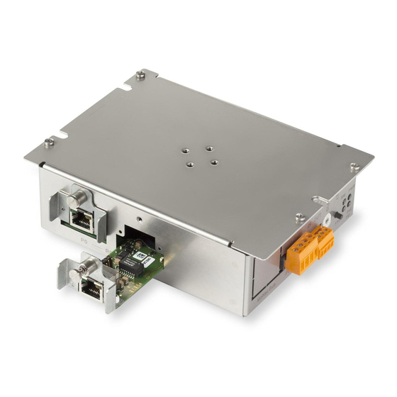
Ethernet switch (modular) FN2012-A1 Description 1 Ethernet switch (modular) FN2012-A1 1.1 Description The Ethernet switch (modular) FN2012 is intended exclusively for the operation of an Ethernet network for the physical connection to voice and VoIP components for use in fire detection. - Page 6 Ethernet switch (modular) FN2012-A1 Description Properties ● Can be installed in approved FS20/FS920 housing ● Can be installed in approved XLS housing ● 2x Ethernet ports for local Ethernet (panel-internal) ● 2x Ethernet ports for external Ethernet (increased EMC safety and ground fault supervision) ●...
-
Page 7: Installation
If the Ethernet switch (modular) is used as a repeater, it is installed as a separate component in an external housing (1HU). Figure 1: Installing the Ethernet switch (modular) in housings (2HU) 7 | 34 A6V10407862_d_en_-- Building Technologies Siemens Industry, Inc. 2018-09-07... - Page 8 2. Inserting the 3 fastening screws (3) into the side tabs (4) and screw the Ethernet switch (2) to the threaded sleeves (5) in the back box (1). 3. Wire up the Ethernet switch according to the wiring information provided below. 8 | 34 Building Technologies A6V10407862_d_en_-- Siemens Industry, Inc. 2018-09-07...
-
Page 9: Installation In Xls Housings
2. Inserting the 3 fastening screws (3) into the side tabs (4) and screw the Ethernet switch (2) to the threaded sleeves (5) in the back box (1). 3. Wire up the Ethernet switch according to the wiring information provided below. 9 | 34 A6V10407862_d_en_-- Building Technologies Siemens Industry, Inc. 2018-09-07... -
Page 10: Installation Of The Ethernet Modules
Threaded hole for fastening Positioning aid Before the Ethernet module (electric) VN2001 is installed, the jumper settings must be plugged in as appropriate for how the module will be used. 10 | 34 Building Technologies A6V10407862_d_en_-- Siemens Industry, Inc. 2018-09-07... - Page 11 4. Use the fastening screw (3) to fix the Ethernet module in the threaded hole (6). 5. Wire up the Ethernet module according to the wiring information provided below. See also 1 Jumper settings on the VN2001 [➙ 23] 11 | 34 A6V10407862_d_en_-- Building Technologies Siemens Industry, Inc. 2018-09-07...
-
Page 12: Views
Not connected Switches and keys CONFIG S302 rotary switch with 16 positions for pre-configured operating modes RESET S301 RESET key with three functions Figure 5: View of Ethernet connections FN2012 12 | 34 Building Technologies A6V10407862_d_en_-- Siemens Industry, Inc. 2018-09-07... - Page 13 Element Des. Function Connector RING port 0, socket X1 for the optional Ethernet module (optical or electric) RING port 1, socket X2 for the optional Ethernet module (optical or electric) 13 | 34 A6V10407862_d_en_-- Building Technologies Siemens Industry, Inc. 2018-09-07...
-
Page 14: Wiring
2x Ethernet external 2x Ethernet internal MoNet Ethernet FCA2031 PMI & Mainboard Panel Figure 7: Wiring of the Ethernet switch (modular) FN2012 All of the connections shown are current-limited and supervised. 14 | 34 Building Technologies A6V10407862_d_en_-- Siemens Industry, Inc. 2018-09-07... - Page 15 Not used Panel Approved Siemens panel in which the Ethernet switch (modular) is being installed The electrical Ethernet cable for the external connections P2 and P3, as well as the connections via the Ethernet module (electric) VN2001 to connections P0 and P1 must be at least 6 ft/2 m long.
-
Page 16: General Wiring Fs20/Fs920
The wiring must be routed as far away as possible from the installed components and the non-current-limited cables and fixed in place appropriately. Cable guides in the housing Current-limited and non-current-limited cables must not be routed together through the same cable entry. 16 | 34 Building Technologies A6V10407862_d_en_-- Siemens Industry, Inc. 2018-09-07... -
Page 17: General Wiring Xls
The Ethernet switch (modular) is supplied via the PSC-12 power supply, connection TB4. ● The internal Ethernet connection is established between port 4 or port 5 on the Ethernet switch (modular) and the PMI-2, connection J11. 17 | 34 A6V10407862_d_en_-- Building Technologies Siemens Industry, Inc. 2018-09-07... -
Page 18: Monet Bus Connection
Ribbon cable connection for MoNet bus Figure 11: Connecting the MoNet bus ribbon cable Connect the 1.35 m/4.43 ft long ribbon cable for the MoNet bus as shown on the κ Ethernet switch (modular). 18 | 34 Building Technologies A6V10407862_d_en_-- Siemens Industry, Inc. 2018-09-07... -
Page 19: Ethernet Switch In The Ethernet Network
PMI & mainboard. If the switch is built into another housing or device, it is supplied with power via a 24 V current-limited and supervised power supply that has been approved for use in fire detection. 19 | 34 A6V10407862_d_en_-- Building Technologies Siemens Industry, Inc. 2018-09-07... - Page 20 The minimum cable length for an electrical 10/100BaseT cable on the VN2001 is 10 ft/3 m. Shorter lengths are only permitted within the same housing, or if the connection does not need to be supervised in accordance with the UL864 standard. 20 | 34 Building Technologies A6V10407862_d_en_-- Siemens Industry, Inc. 2018-09-07...
-
Page 21: Ethernet Switch As A Repeater
Jumper settings on the VN2001 with one repeater: Switch/repeater VN2001 in port P1 VN2001 in port P0 Switch 1 Not connected Repeater Neutral position Switch 2 Ground fault supervision Not connected 21 | 34 A6V10407862_d_en_-- Building Technologies Siemens Industry, Inc. 2018-09-07... - Page 22 ● The switch carries out ground fault supervision as far as the repeater. ● If there are two repeaters, the first one transfers ground fault supervision to the second repeater. 22 | 34 Building Technologies A6V10407862_d_en_-- Siemens Industry, Inc. 2018-09-07...
-
Page 23: Jumper Settings On The Vn2001
The slots the jumpers are plugged into on the Ethernet module (electric) differ depending on how the module will be used. The table below shows the different settings for the corresponding function. X102 Figure 16: View of VN2001 with jumper strip 23 | 34 A6V10407862_d_en_-- Building Technologies Siemens Industry, Inc. 2018-09-07... - Page 24 Jumper settings on the VN2001 X102 jumper strip Jumper setting on X102 Function Ground fault supervision activated PoE activated Neutral position, function deactivated PoE for cables crossed at one end 24 | 34 Building Technologies A6V10407862_d_en_-- Siemens Industry, Inc. 2018-09-07...
-
Page 25: Pin Assignments
Supply input 1 (+DC 24 V) Common supply input 1 (DC 0 V) Not connected Not connected Admissible cable cross-section: AWG 24...AWG 12 / 0.2...2.5 mm² Connector FN2012 POWER Terminal Plug +24V Supply input 25 | 34 A6V10407862_d_en_-- Building Technologies Siemens Industry, Inc. 2018-09-07... -
Page 26: Fault' Connector Strip
Dry contact relay 2 (common, normally open) Not connected Not connected Admissible cable cross-section: AWG 24...AWG 12 / 0.2...2.5 mm² F4 F3 F2 F1 Connector Terminal Plug Cover cap (open) 26 | 34 Building Technologies A6V10407862_d_en_-- Siemens Industry, Inc. 2018-09-07... -
Page 27: Indicators
1375 1500 1625 1750 1875 Fatal FAULT Ethernet switch is generating some [ms] 875 1000 1125 1250 1375 1500 1625 1750 1875 other fault Table 2: FAULT LED flashing pattern 27 | 34 A6V10407862_d_en_-- Building Technologies Siemens Industry, Inc. 2018-09-07... - Page 28 Claim Manager Ethernet switch is acting as the manager [ms] 875 1000 1125 1250 1375 1500 1625 1750 1875 but has not been configured to perform this role 28 | 34 Building Technologies A6V10407862_d_en_-- Siemens Industry, Inc. 2018-09-07...
- Page 29 Unidirectional Data Link ● Check the cabling of all optical fiber sections Fault ● Replace each Ethernet switch in turn until you identify the defective device. Table 5: Troubleshooting 29 | 34 A6V10407862_d_en_-- Building Technologies Siemens Industry, Inc. 2018-09-07...
-
Page 30: Adjustment Elements
Press for >10 s Lights up and goes out as soon as The switch is in firmware update mode. The the switch is in update mode reset key can be released. 30 | 34 Building Technologies A6V10407862_d_en_-- Siemens Industry, Inc. 2018-09-07... - Page 31 192.168.99.243 255.255.248.0 192.168.99.244 255.255.248.0 192.168.99.245 255.255.248.0 192.168.99.246 255.255.248.0 192.168.99.247 255.255.248.0 192.168.99.248 255.255.248.0 192.168.99.249 255.255.248.0 192.168.99.250 255.255.248.0 192.168.99.251 255.255.248.0 192.168.99.252 255.255.248.0 Reserved (0.0.0.0) Reserved (255.255.255.255) Repeater mode Repeater mode 192.168.200.4 255.255.255.0 31 | 34 A6V10407862_d_en_-- Building Technologies Siemens Industry, Inc. 2018-09-07...
-
Page 32: Technical Data
120+/-3°F to 32+/-3°F Rel. humidity during operation 93+/-2% at a temperature of 90+/-3°F Protection category IP30 The length is a guide value dependent upon the loss of the optical cable 32 | 34 Building Technologies A6V10407862_d_en_-- Siemens Industry, Inc. 2018-09-07... -
Page 33: Fcc Statement
33 | 34 A6V10407862_d_en_-- Building Technologies Siemens Industry, Inc. 2018-09-07... - Page 34 Issued by © Siemens Industry, Inc., 2015 Siemens Industry, Inc. Technical specifications and availability subject to change without notice. Building Technologies Division 8 Fernwood Road Florham Park, NJ 07932 +1 973-593-2600 www.sbt.siemens.com/FIS Document ID: A6V10407862_d_en_-- SAP order no.: A5Q00060099 Edition: 2018-09-07...
Need help?
Do you have a question about the FN2012-A1 and is the answer not in the manual?
Questions and answers