Advertisement
Technote 2: Setting up MS-551 Stereo Modulators
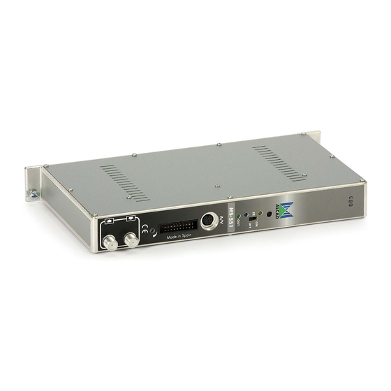
Vestigial Side Band TV Stereo Modulators generate an
analogue TV channel from the audio and video signals .MS-551
Stereo modulators comprise SAW filtering for maximum
harmonic reduction and true VSB response for adjacent channel
operation.
Launch Amplifier
Power Supply
IMPORTANT: Layout of the modules must be as shown above. Power Supply (FA-
310/312) must be located on the far left hand side and launch amplifier (PA-720)
must be the next module in the chain. Please look at the above picture.
AIM PROGRAMMER TO IR SENSOR LOCATED ON EACH
MODULATOR WHEN PROGRAMMING
Programming of Modules
Ensure the following prior to programming:
• It is necessary to connect all the modules to the support frame SP-226 (code
9120130) for the system to function.
• It is also recommended that you make the earth connection to the building
using a cable with a section of at least 4 mm.
• Ensure that you have the Alcad programmer PS-003 with firmware version
4.7 or later.
• Power supply/Control cable must be plugged into each module.
ADD OR REMOVE
wall outlet. Always disconnect the equipment, and then reconnect it to the
mains supply so that the amplifier recognises the new module. Failure to do
so can cause equipment to fail.
modules without disconnecting mains supply power from
DO NOT
Advertisement
Table of Contents

Related Manuals for Alcad MS-551


Summary of Contents for Alcad MS-551
- Page 1 • It is also recommended that you make the earth connection to the building using a cable with a section of at least 4 mm. • Ensure that you have the Alcad programmer PS-003 with firmware version 4.7 or later.
- Page 2 For optimum results installers The MS-551 modulators use an 8 pin Mini-Din cable that is available from your local ALCAD dealer. The mini DIN connection is located on the front of the modulator. Please look at picture below for example.
- Page 3 • CD-113 (cod. 9120094) Stereo, with a miniDIN to RCA connection. 1.0 Programming of the Modulator To program the modulator, place the programming switch in the ON (upward) position which can be seen from picture below. When you turn the switch in the “ON” position the programming indicator will light up.
- Page 4 You must then select the model you are trying to program. Scroll left or right using the arrows until you get screenshot below You will then need to press the up arrow and you will then see the screen “Table channels B/G CCIR“on the programmer screen. This can be seen below Press the left arrow once so that you can see the screen shot as below “Table channels frequency”.
- Page 5 AUSTRALIAN DIGITAL/ANALOGUE FREQUENCY TABLE The next screen enables the type of Audio output that is to be selected stereo or mono...
- Page 6 Once you have the desired audio output press transmit to ensure setting is sent to module, then press the down arrow to go to the next screen below. The “Audio level” screen enables manipulation of the Audio Sub-carrier from the modulator.
Need help?
Do you have a question about the MS-551 and is the answer not in the manual?
Questions and answers