Table of Contents
Advertisement
Quick Links
Com. no.
..................................................
Operator
............................................................................................................................................................
Operating place ........................................................................................................................................................
Swing door drive mechanism
ETS 73
Mounting and operating instructions
Pos.
0548-990/52g
Original
.................................
2019.10
Construction year ...................
Advertisement
Table of Contents

Related Manuals for Eco ETS 73


Summary of Contents for Eco ETS 73
- Page 1 Swing door drive mechanism ETS 73 Mounting and operating instructions Original Com. no........... Pos........Construction year ....Operator ................................Operating place ................................ 0548-990/52g 2019.10...
-
Page 2: Table Of Contents
ETS 73 Mounting and operating instructions TABLE OF CONTENTS GENERAL REMARKS ........................ 5 Target group ........................5 Where to keep these instructions .................. 5 Adresses ......................... 5 Auxiliary tools and service performances ..............6 SAFETY ............................7 Appropriate use ......................7 Safety notices ......................... - Page 3 ETS 73 Mounting and operating instructions ELECTRICAL CONNECTIONS ....................49 Power supply ....................... 49 Cable layout ......................... 51 5.2.1 Lintel mounting ..................... 51 5.2.2 Leaf mounting ....................51 External elements ......................52 Motorized lock ......................53 5.4.1 Motorised lock with direct connection to motor coil ........53 5.4.2...
- Page 4 Open position stop piece integrated in the drive mechanism ........92 13.4 Connection plate for wooden door leaf (normal rods) ..........92 13.5 Mounting plate ......................93 13.6 Mounting plate ETS 73 Mod ..................93 13.7 Continuous covering ....................94 13.8 Optional PCBs ......................95 13.8.1 Relay PCB .......................
-
Page 5: General Remarks
The present instructions have to be kept close to the installation, together with the control book- let! Adresses Distribution agent/ After-sales service Distribution ECO Schulte GmbH & Co. KG Iserlohner Landstrasse 89 D-58706 Menden Tel. +49 23 73 / 92 76-0 +49 23 73 / 92 76-40 www.eco-schulte.de... -
Page 6: Auxiliary Tools And Service Performances
ETS 73 Mounting and operating instructions 1.4 Auxiliary tools and service performances The auxiliary tools and service performances listed hereafter are available, depending on the respective situation and authorization (please ask your distribution agent): • Company portrait • Homepage • News • Info-News via E-mail •... -
Page 7: Safety
2.1 Appropriate use The swing door drive mechanism ETS 73 has been exclusively designed for operating swing doors. Any other use beyond these application limits is deemed inappropriate and inadmissible! In the event of an inappropriate use of this system, the safety of the user may be jeopar dized and/or the installation be damaged. - Page 8 • In its assembled state, the installation must answer all the safety requirements specified by the machinery directive. • The swing door drive mechanism ETS 73 may only be installed and operated in dry rooms. If this condition cannot be fulfilled, the customer must provide sufficient protection from moisture.
-
Page 9: Service
A safe and reliable function of the installation can only be guaranteed if it is operated with the original ECO Schulte GmbH & Co. KG accessories/spare parts. ECO Schulte GmbH & Co. KG decli- nes all responsibility for damages resulting from unauthorized modifications of the installation or from the use of foreign accessories/spare parts. -
Page 10: Product Description
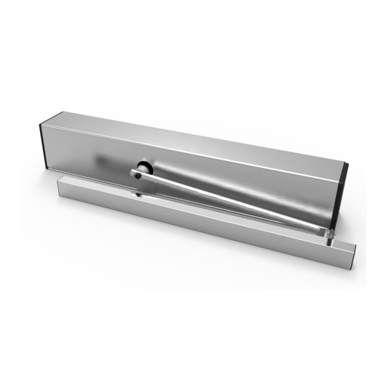
ETS 73 Mounting and operating instructions PRODUCT DESCRIPTION 3.1 General remarks The swing door drive mechanism ETS 73 opens and closes the door leaf via a rod assembly (is not shown in the illustration). Drive mechanism Drive mechanism covering Side cover Spring unit... -
Page 11: Standard Application
3.3 Inverse application The swing door drive mechanism ETS 73 is also appropriate for inversed operation. This particular function can be separately programmed for each drive mechanism. In the event of a power failu- re, the inverse application ensures that the door leaf is reliably opened. -
Page 12: Automatic Closing Sequence Control
ETS 73 Mounting and operating instructions 3.4 Automatic closing sequence control For bi-parting installations, two separate ETS 73 swing door drive mechanisms are used, which are connected via the CAN bus system. Drive mechanism 1 Master Drive mechanism 2 Slave Earlier door leaf... -
Page 13: Technical Data
ETS 73 Mounting and operating instructions 3.6 Technical data Drive mechanism Standard Power transmission Normal rods Sliding rods Dimensions drive mechanism Height 95 mm Width 690 mm Depth 120 mm Weight drive mechanism 10,5 kg Ambient temperature -15...+50 °C May only be used in dry rooms max. -
Page 14: Application Limits Without Safety Elements According To En 16005
ETS 73 Mounting and operating instructions 3.7 Application limits without safety elements according to EN 16005 Warning: In the event of swing doors installed in a non publicly accessible areas, without ins- tallation of safety elements that monitor the door leaf movement, the setting values specified hereafter for the opening speed Vo and the closing speed Vc must not be exceeded. -
Page 15: Maximum Wind-Load Capacity
ETS 73 Mounting and operating instructions 3.8 Maximum wind-load capacity Normal rods pushing function (lintel mounting) 3000 2900 2800 2700 2600 2500 2400 2300 2200 2100 2000 1000 1100 1200 1300 1400 1500 1600 Clearance width in mm Sliding rods pushing function (lintel mounting) 3000 2900 2800 2700... - Page 16 ETS 73 Mounting and operating instructions Sliding rods pushing function (leaf mounting) 3000 2900 2800 2700 2600 2500 2400 2300 2200 2100 2000 1000 1100 1200 1300 1400 1500 1600 Clearance width in mm 0548-990/52g 0548-990-51---60g_2019.10.indd Page 16 of 98...
-
Page 17: Mounting
ETS 73 Mounting and operating instructions MOUNTING 4.1 Preparation Attention: Standard application It is recommended that a door leaf stop piece be mounted by the customer. Inverse application It is imperative for the customer to install a door leaf stop piece! This stop piece prevents the door leaf from being damaged in the manual operating mode. -
Page 18: Mounting Versions
ETS 73 Mounting and operating instructions 4.2 Mounting versions 4.2.1 Rod assemblies narrow RS/RG DIN left DIN right Normal rods 0548-163/01 pushing function Normal rods 0548-163/01 pushing function Lintel mounting see chapter 4.4.1 Lintel mounting see chapter 4.4.1 Lintel depth 0...250 mm Lintel depth 0...250 mm Drive mechanism... -
Page 19: Rod Assemblies Stainless Steel
ETS 73 Mounting and operating instructions 4.2.2 Rod assemblies stainless steel DIN left DIN right Normal rods 0548-104 Normal rods 0548-104 pushing function 0548-104/01 KTL pushing function 0548-104/01 KTL Lintel mounting see chapter 4.5.1 Lintel mounting see chapter 4.5.1 Lintel depth 0...250 mm Lintel depth 0...250 mm... -
Page 20: General
ETS 73 Mounting and operating instructions 4.3 General Warning: The fastening bases must provide sufficient solidity. If necessary they have to be rein- forced by the appropriate means. Attention: The maximum admissible undulation of the fastening base is 1 mm. The drive me-... -
Page 21: Rod Assemblies Narrow Rs/Rg
ETS 73 Mounting and operating instructions 4.4 Rod assemblies narrow RS/RG 4.4.1 Normal rods RS pushing function / Lintel mounting Material: Drive mechanism 0548-030 Covering aluminium Drive mechanism 0548-031 Covering inox incl. fixing set 0548-107 Normal rods 0548-163/01 Procedure: Mark out and drill the fastening holes on the lintel and the door leaf. - Page 22 ETS 73 Mounting and operating instructions without mounting plate Options Axle extension (mm) (mm) (mm) Standard 0548-190 9...19 0548-191 9...29 0548-192 9...39 0548-193 9...49 0548-194 9...59 DIN right = as shown DIN left = mirror-inverted Chassis profile Lower edge door frame Ø20...
- Page 23 ETS 73 Mounting and operating instructions with mounting plate Options Axle extension (mm) (mm) (mm) Standard 0548-190 3...13 0548-191 3...23 0548-192 3...33 0548-193 3...43 0548-194 3...53 DIN right = as shown DIN left = mirror-inverted Fixing drive Fixing mechanism mounting plate Ø20...
- Page 24 ETS 73 Mounting and operating instructions Drive mechanism standard Inverse application 5. Close the door leaf. 5. Separate the rotating arm (C) from the rod arm (B) by loosen the screw (E). 6. Separate the rotating arm (C) from the rod arm (B) by loosen the screw (E).
- Page 25 ETS 73 Mounting and operating instructions Inverse application 1. Let the door leaf be opened by spring power. 2. Using a screwdriver, carefully prize the service cover (C) out of the gearbox housing. 3. By means of a socket wrench 1,5 mm, slightly loosen the locking screw (B) and leave the socket wrench inserted in the locking screw (B).
-
Page 26: Sliding Rods Rg Pulling Function / Lintel Mounting
ETS 73 Mounting and operating instructions 4.4.2 Sliding rods RG pulling function / Lintel mounting Material: Drive mechanism 0548-030 Covering aluminium Drive mechanism 0548-031 Covering inox incl. fixing set 0548-107 Sliding rods 0548-164/01 650 mm incl. sliding bolts 18/46 mm Procedure: Mark out and drill the fastening holes on the lintel and the door leaf. - Page 27 ETS 73 Mounting and operating instructions without mounting plate Lintel Min. width door Max. door Options Axle extension depth leaf (mm) opening (mm) (mm) (mm) (mm) (mm) without / with angle without / with Standard 26...51 FLATSCAN (°) FLATSCAN 0548-190 36...61 -30...+30...
- Page 28 ETS 73 Mounting and operating instructions with mounting plate DIBt Lintel Min. width door Max. door Options Axle extension che- depth leaf (mm) opening (mm) (mm) (mm) (mm) cked (mm) without / with angle without / with Standard 26...51 FLATSCAN (°) FLATSCAN 0548-190 36...61...
- Page 29 ETS 73 Mounting and operating instructions Drive mechanism standard Inverse application 6. Close the door leaf. 6. Mount the drive mechanism. 7. Prior to the installation of the drive unit: 7. Open the door leaf (max. 115°). Screw down the lever arm (D) on the drive unit ...
-
Page 30: Sliding Rods Rg Pushing Function / Lintel Mounting
ETS 73 Mounting and operating instructions 4.4.3 Sliding rods RG pushing function / Lintel mounting Material: Drive mechanism 0548-030 Covering aluminium Drive mechanism 0548-031 Covering inox incl. fixing set 0548-107 Sliding rods 0548-164/01 650 mm incl. sliding bolts 18/46 mm Procedure: Mark out and drill the fastening holes on the lintel and the door leaf. - Page 31 ETS 73 Mounting and operating instructions without mounting plate Lintel Min. width door Max. door ope- Options Axle extension depth leaf ning angle (mm) (mm) (mm) (mm) (mm) (°) (mm) Standard -30...+10 0548-190 9...19 11...20 0548-191 9...29 21...30 0548-192 9...39 31...50 0548-193 9...49...
- Page 32 ETS 73 Mounting and operating instructions with mounting plate DIBt Lintel Min. width door Max. door ope- Options Axle extension che- depth leaf ning angle (mm) (mm) (mm) cked (mm) (mm) (°) (mm) Standard -30...0 0548-190 3...13 1...10 0548-191 3...23 11...20...
- Page 33 ETS 73 Mounting and operating instructions Drive mechanism standard Inverse application 7. Close the door leaf. 7. Open the door leaf (max. 115°). 8. Screw down the lever arm (D) on the drive unit 8. Slide the open position stop piece (B) into the sliding Tightening moment 25 Nm.
-
Page 34: Rod Assemblies Stainless Steel
ETS 73 Mounting and operating instructions 4.5 Rod assemblies stainless steel 4.5.1 Normal rods pushing function / Lintel mounting Material: Drive mechanism 0548-030 Covering aluminium Drive mechanism 0548-031 Covering inox incl. fixing set 0548-107 Normal rods 0548-104 Normal rods KTL 0548-104/01 Procedure: Mark out and drill the fastening holes on the lintel and the door leaf. - Page 35 ETS 73 Mounting and operating instructions Drive mechanism standard Inverse application 2. If existing: 2. Mount the drive mechanism. Sub-assemble the drive-internal open position stop piece, integrated in the drive mechanism (see Option 3. Close the door leaf. instructions 0548-992/02).
-
Page 36: Sliding Rods Pulling Function / Lintel Mounting
ETS 73 Mounting and operating instructions 4.5.2 Sliding rods pulling function / Lintel mounting Material: Drive mechanism 0548-030 Covering aluminium Drive mechanism 0548-031 Covering inox incl. fixing set 0548-107 Sliding rods 0548-134 620 mm incl. sliding bolts 14/38 mm Sliding rods KTL 0548-105/01 620 mm incl. sliding bolts 14/38 mm... - Page 37 ETS 73 Mounting and operating instructions Lintel depth Min. width door Max. door ope- Rod assem- (mm) leaf (mm) ning angle blies (mm) (mm) (mm) without / with (°) (art. no.) without / with FLATSCAN FLATSCAN -30...+50 740 / 810...
- Page 38 ETS 73 Mounting and operating instructions Drive mechanism standard Inverse application 2. Close the door leaf. 2. If existing: Sub-assemble the drive-internal open position stop 3. Install the mounting profile (E) on the door leaf. piece, integrated in the drive mechanism (see Option instructions 0548-992/02).
-
Page 39: Sliding Rods Pushing Function / Lintel Mounting
ETS 73 Mounting and operating instructions 4.5.3 Sliding rods pushing function / Lintel mounting Material: Drive mechanism 0548-030 Covering aluminium Drive mechanism 0548-031 Covering inox incl. fixing set 0548-107 Sliding rods 0548-134 620 mm incl. sliding bolts 14/38 mm Sliding rods KTL 0548-105/01 620 mm incl. sliding bolts 14/38 mm... - Page 40 ETS 73 Mounting and operating instructions Lintel depth Min. width door Max. door opening Rod assem- leaf angle blies (mm) (mm) (°) (art. no.) (mm) (mm) (mm) -30...+20 0548-105 21...30 0548-105 31...40 0548-105 41...60 0548-105 61...70 0548-105 -30...+200 0548-105/02 With lintel depths >150 mm we recommend using the normal rods.
- Page 41 ETS 73 Mounting and operating instructions Drive mechanism standard Inverse application 2. Mount the drive mechanism. 2. If existing: Sub-assemble the drive-internal open position stop 3. Close the door leaf. piece, integrated in the drive mechanism (see Option instructions 0548-992/02).
-
Page 42: Sliding Rods Pushing Function / Leaf Mounting
ETS 73 Mounting and operating instructions 4.5.4 Sliding rods pushing function / Leaf mounting Material: Drive mechanism 0548-030 Covering aluminium Drive mechanism 0548-031 Covering inox incl. fixing set 0548-107 Sliding rods 0548-105/02 830 mm incl. sliding bolts 14/38 mm Procedure: Mark out and drill the fastening holes on the lintel and the door leaf. - Page 43 ETS 73 Mounting and operating instructions DIN left = as shown DIN right = mirror-inverted Upper edge door leaf Chassis profile Lintel depth Axis of rotation -30...0 0...+200 Clamping piece standard Sliding bolt 14 mm Options 0548-114 Clamping piece standard 10...18...
- Page 44 ETS 73 Mounting and operating instructions Mount the drive mechanism. Close the door leaf. Install the mounting profile (E) on the lintel. Screw down the rotating arm (B) parallel to the drive mechanism. Push the guide profile (G) over the glider (C) and hook it into the mounting profile (E).
-
Page 45: Adjusting The Pre-Stressing Of The Closing Spring
ETS 73 Mounting and operating instructions 4.6 Adjusting the pre-stressing of the closing spring Upon delivery, the closing spring is pre-stressed for a measure X* = 26 mm. To ensure a safe and optimal operation of the swing door drive mechanism, the correct pre-stressing must be adjusted for the closing spring (by means of the setting screw). - Page 46 ETS 73 Mounting and operating instructions Inverse application EN class EN 3 EN 4 EN 5 EN 6 EN 7 Width of door leaf 950 mm 1'100 mm 1'250 mm 1'400 mm 1'600 mm Normal rods Measure X * 40 mm 36 mm...
-
Page 47: Setting The Accelerating Function (Forceful Closing)
ETS 73 Mounting and operating instructions 4.7 Setting the accelerating function (forceful closing) Note: The accelerating function (forceful closing) is only activated for the standard drive mechanism. 4.7.1 Accelerating force While an installation is in the state “without mains power” or in the operating mode MANUAL, the motor acts as an attenuator, thus guaranteeing a constant closing speed until the Closed posi- tion is reached. -
Page 48: Forceful Closing Range
ETS 73 Mounting and operating instructions 4.7.2 Forceful closing range Upon delivery from the factory, the activation of the accelerating function (forceful closing) is pre- set (i.e. it intervenes approx. 5° before reaching the closed position). Under normal conditions, it will not be necessary to change the default setting! However, in cases where in the de-energized... -
Page 49: Electrical Connections
ETS 73 Mounting and operating instructions ELECTRICAL CONNECTIONS 5.1 Power supply Warning: Before working on the drive mechanism, make sure that the mains cable is voltage- free! The mains supply line including mains plug (with respective protection) has to be provided by customers. - Page 50 ETS 73 Mounting and operating instructions Program selector further away from the door hinges PE ~1 ~2 PE L' N' Strain relief PE ~1 ~2 PE L' N' 0548-990/52g 0548-990-51---60g_2019.10.indd Page 50 of 98...
-
Page 51: Cable Layout
ETS 73 Mounting and operating instructions 5.2 Cable layout 5.2.1 Lintel mounting (614) 5.2.2 Leaf mounting Socket by customers Option Flexible power supply system 0548-209 0548-990/52g 0548-990-51---60g_2019.10.indd Page 51 of 98... -
Page 52: External Elements
ETS 73 Mounting and operating instructions 5.3 External elements Mount all the required control and safety elements at their respective place. Lead the cables of the elements up to the drive mechanism (by customers). Connect the cables according to the diagram E4-0141-713_ECO (in the appendix). -
Page 53: Motorized Lock
ETS 73 Mounting and operating instructions 5.4 Motorized lock The swing door drive mechanism and its control unit are always configured as Master. All the commands are transmitted to this control unit. The latter then unlocks/locks the motorized lock. Functional performance: Opening command Impulse and permanent command transmitted to motorised lock ... -
Page 54: Motorized Lock With Own Evaluation Control
ETS 73 Mounting and operating instructions 5.4.2 Motorized lock with own evaluation control The motorized lock is equipped with an own evaluation control (either integrated or external). The swing door drive mechanism is configured as the Master unit and transmits a voltage free impulse for control unit of the motorized lock for relasing the latter. The electric power is supplied directly via the swing door drive mechanism (i.e. -
Page 55: Motorized Lock With Separate Evaluation Control/Power Pack
ETS 73 Mounting and operating instructions 5.4.3 Motorized lock with separate evaluation control/power pack The motorized lock is equipped with a separate evaluation control and a separate power pack ensuring the power supply. The swing door drive mechanism is configured as the Master and transmits a voltage free impulse to the control unit of the motorized lock for releasing the latter. -
Page 56: Commissioning
ETS 73 Mounting and operating instructions COMMISSIONING Warning: During the setting-up procedure (which must only be carried out by experts), the safety devices (radar, sensors, ...) are switched off! Before initiating the setting-up procedure, it is important to make sure that neither... - Page 57 ETS 73 Mounting and operating instructions Adjust the opening speed Vo and validate by means of OK. Adjust the closing speed Vc and validate by means of OK. If desired: Invers Program the inverse application (spring-powered opening) and vali- date it by pressing OK.
-
Page 58: Inverse Application
ETS 73 Mounting and operating instructions Note: A renewed setting-up procedure (Teach) is required if: • the spring tension has been changed • the leaf weight has been changed • the type of rod assembly has been changed • the opening angle Ao has been changed •... -
Page 59: Closing Sequence Control
ETS 73 Mounting and operating instructions 6.2 Closing sequence control For bi-parting installations, the closing sequence control determines the order in which the door leaves are opened and closed. For the opening procedure, the earlier door leaf (Master leaf) is the first one to be opened, whereas for the closing procedure the delayed door leaf (Slave leaf) is the first one to be closed. - Page 60 ETS 73 Mounting and operating instructions Function: The first door leaf to be put in motion for the opening procedure is the Master; by means of DubleD, this leaf is configured as MastrA. Its partner is the Slave, which is configured as SlaveA by means of DubleD.
- Page 61 ETS 73 Mounting and operating instructions Procedure: Connect both control units by means of the CAN cable 0383-194/07 (by plugging it into the socket X117). Note: The respective control and safety elements are connected to the corresponding drive mechanism. Take the Master drive mechanism into operation (see chapter 6).
-
Page 62: Interlock Operation
ETS 73 Mounting and operating instructions 6.3 Interlock operation Procedure: Note: Both installations must be plugged Exterior side into resp. out of the same power supply. Side A Connect both control units by means of the CAN cable (by plugging it into the socket X117). -
Page 63: Adhesive Labels
ETS 73 Mounting and operating instructions 6.4 Adhesive labels 6.4.1 Service sticker Service Attach the service sticker (outside) onto the sticker degreased surface of the drive mechanism 0460-816 covering, at a place that is easily visible for the customer..Stick the monthly sticker onto the service... -
Page 64: Mount The Drive Mechanism Covering
ETS 73 Mounting and operating instructions 6.5 Mount the drive mechanism covering Material: Covering 0548-400 Aluminium Covering accessories 0548-143 Aluminium Covering 0548-303 Stainless steel Covering accessories 0548-115 Stainless steel Procedure: Mount the covering and the accessories as shown in the illustration. 0548-364 Alu 0548-400 Alu... -
Page 65: Control
ETS 73 Mounting and operating instructions CONTROL 7.1 Main switch The drive mechanism is supplied with a built-in main switch (A). This main installation switch enables you to disconnect the power supply from the drive mechanism. The door leaf then is closed from any position by means of spring power (Invers = spring opening, unless the door leaf has not been locked). -
Page 66: Operating Modes
ETS 73 Mounting and operating instructions 7.3 Operating modes The following operating modes can be enabled by means of the program selector: AUTOMATIC Automatic opening via the opening elements inside/outside + Key. Automatic closing upon expiration of the adjustable hold-open time. -
Page 67: Adjustings
ETS 73 Mounting and operating instructions 7.4 Adjustings Joystick The parameters can be changed on the Display control unit by means of the display and the scroll joystick. The movements of the joystick have the change following effects: •... -
Page 68: Configuration (Config)
ETS 73 Mounting and operating instructions 7.4.2 Configuration (CONFIG) Parameter Description Setting range Default APuGo Triggering angle Push&Go (angle push&go) OFF, 2...10° ASES 1) Suppression point Safety Element stop (angle safety element stop). 45°...Ao 95° If Ao is changed, ASES is auomatically set to Ao. -
Page 69: Installations With Multiple Door Leaves (Double Door)
ETS 73 Mounting and operating instructions open open ASES closed closed 7.4.3 Installations with multiple door leaves (DOUBLE DOOR) Parameter Description Setting range Default Closing sequence role (Master/Slave) and interlock side (A/B) DubleD MastrA SlaveA MastrB SlaveB AoSeq Current delay angle for opening sequence control (Slave) 0..110°... -
Page 70: Menu Navigation
ETS 73 Mounting and operating instructions 7.4.4 Menu navigation 0548-990/52g 0548-990-51---60g_2019.10.indd Page 70 of 98... - Page 71 ETS 73 Mounting and operating instructions On the 1st level, the following information is shown on the display: 1st display line: The door position is represented by means of the arrows (><). Alternatively, the motion-relevant opening and safety signals are displayed. The double hash signs (##) indicate that the door is locked.
- Page 72 ETS 73 Mounting and operating instructions DIAGNOSTICS Diagnostic tools • K-I-O-R-S-E shows the inputs KEY (K), OEI (I), OEO (O), SER (R), SES (S), EMY (E). (+) stands for active, (-) for inactive. • 5.1A 95° shows the motor current and the door opening angle.
- Page 73 ETS 73 Mounting and operating instructions BLOCK/UNBLOC Lock/unlock the joystick • BLOCK Lock the joystick. For a temporary unlocking, press OK for more than 1 second. 60 seconds after the last joystick actuation, the joystick is automatically relocked. • UNBLOC Permanent unlocking of the joystick.
-
Page 74: Service
ETS 73 Mounting and operating instructions SERVICE A regular service (maintenance/checking) is absolutely indispensable in order to guarantee a safe operation and long lifetime of the installation. The service must be carried out by a expert, at least once a year, according to the following checklist. -
Page 75: Service For Pedestrian Doors
Rating plate, arrow sticker, glass sticker, etc. existing? Control booklet existing and completed? Only for redundant drive mechanisms. ECO cleans all the elements of the installation provided this is necessary for the function of the installation. A general cleaning of the installation is not planned. 0548-990/52g 0548-990-51---60g_2019.10.indd... -
Page 76: Fundamental Checking
ETS 73 Mounting and operating instructions 8.2 Fundamental checking Warning: Switch the main installation switch off on the drive mechanism! Dismount the covering of the drive mecha- nism. Check all the cable connections. Normal rods: Separate the rod arm (B) from the rotating arm (A): Pull the spherical joint (C) apart. -
Page 77: Troubleshooting
ETS 73 Mounting and operating instructions TROUBLESHOOTING Warning: Electrocution hazard! Before working on any live elements, pull out the mains plug respectively switch off the main installation switch! If a malfunction occurs which might be detrimental to the safety of the users, and which cannot be eliminated without delay, the operator must be informed and if requi- red the installation shall be taken out of operation. -
Page 78: Operating
ETS 73 Mounting and operating instructions 9.1.2 Operating Description Cause Elimination Checking time Reaction E10 01 Fullteach required Parameter Ao, Rod, Invers or Carry out a teach. Upon changing the dAxis changed. drive mechanism configuration. Minimum opening angle has not Check the locking/electric lock. -
Page 79: System
ETS 73 Mounting and operating instructions 9.1.5 System Description Cause Elimination Checking time Reaction E50 01...99 System error Unexpected hard- Switch the drive mechanism off/on. Permanent. W or H or F ware or software Carry out a Factory Reset, carry out a Software Update, E51 01...99... -
Page 80: Malfunction Without Error-No
ETS 73 Mounting and operating instructions 9.2 Malfunction without error-no. In some cases, it will be technically impossible to display an "irregular functioning" of the instal- lation by a definite error number. An alleged error may by all means also be due to "correct" cau- ses. -
Page 81: Software Update Via Usb
Mounting and operating instructions 9.3 Software update via USB A software update of the ETS 73 control unit can be easily and rapidly achieved by means of an USB memory stick. Note: Not all the USB memory sticks can be used. We thus recommend a previous testing of their function together with the ETS 73. -
Page 82: Procedure
Procedure X112 X104 X102 X116 X106 Switch off the main installation X115 X117 switch on the ETS 73. 30 V Plug the USB stick into the control unit socket X118. X118 Switch on the main installations X110 X108 switch on the ETS 73. -
Page 83: Shut-Down
ETS 73 Mounting and operating instructions SHUT-DOWN No particular measures need to be taken for de-commissioning the installation. If the swing door drive mechanism will not be used during at least 1 month, it is recommended to pull out the mains plug. -
Page 84: Disposal Of The Installation
ETS 73 Mounting and operating instructions DISPOSAL OF THE INSTALLATION An ecologically acceptable disposal of the installation is ensured if the different materials are separated and recycled. No particular measures are required for the protection of the environment. However, the relevant legal prescriptions... -
Page 85: Spare Parts
ETS 73 Mounting and operating instructions SPARE PARTS Article No. Designation Remark 0548-116 Drive module 0548-204 Switch support complete 0548-107 Fixing set 0548-358 Mounting plate Option 0548-360 Mounting plate Mod. Option 0548-106 Open stop piece integrated into the drive mechanism Option 0548-118... -
Page 86: Options
The D-BEDIX is connected to the control unit ETS 73 via a screened two-core connection cable (e.g. U72M or EIB-Y(St)Y, max. length 50 m). Only one D-BEDIX can be connected per door installation. -
Page 87: Operating Modes
ETS 73 Mounting and operating instructions 13.1.3 Operating modes With the D-BEDIX, the following operating modes can be selected by means of the corresponding symbols: AUTOMATIC Automatic operation. The installation can be locked. NIGHT The installation is locked . As opening commands, only the key-operated impulse switch is accepted. -
Page 88: Menu Level
ETS 73 Mounting and operating instructions 13.1.5 Menu level Short and simultaneous actuation of both arrow keys (=access to the menu level). Select the desired menu item bymeans of the arrow key. Confirm by means of the OK key. Display Description... -
Page 89: Setting Examples
ETS 73 Mounting and operating instructions 13.1.6 Setting examples Changing the operating mode Select the desired symbol by means of the arrow key (symbol starts flashing). Confirm with the OK key (frame/bar switch over). Preselecting the operating mode An overriding switch is active and determines the operating mode (only the selection frame is visible, the bar underlines the preselected operating mode). -
Page 90: Error Display
ETS 73 Mounting and operating instructions Parameters (hold-open timeday) Short simultaneous actuation of the arrow keys (= access to the menu level). By means of the arrow key, select TOEx. Confirm with the OK key. By means of the arrow key, change the value. -
Page 91: Kombi-D-Bedix
ETS 73 Mounting and operating instructions 13.2 KOMBI-D-BEDIX In addition to the functions of the D-BEDIX, the KOMBI-D-BEDIX contains a key-operated switch (round or profile cylinder) with the following function: Lockout of the KOMBI-D-BEDIX against unautho- rized use. Free Locked... -
Page 92: Open Position Stop Piece Integrated In The Drive Mechanism
ETS 73 Mounting and operating instructions 13.3 Open position stop piece integrated in the drive mechanism Attention: It is recommended that a stop piece be mounted by the customer. This stop piece pre- vents the door leaf from being damaged in the manual operating mode. As an option, an open position stop piece can be integrated into the drive mechanism itself. -
Page 93: Mounting Plate
Mounting and operating instructions 13.5 Mounting plate In cases where the fastening holes provided in the chassis profile of the ETS 73 cannot be used, the mounting plate 0548-358 can be used as an alternative. Attention: The mounting measures according to chapter 4 must be verified and complied with! Ø12,4 x 90°... -
Page 94: Continuous Covering
ETS 73 Mounting and operating instructions 13.7 Continuous covering For bi-parting installations, the two drive mechanisms can be optically connected by inserting an intermediate covering piece. Set with drive mechanism covering 1,9 m Alu 0548-214 Set with drive mechanism covering 1,2 m Alu... -
Page 95: Optional Pcbs
ETS 73 Mounting and operating instructions 13.8 Optional PCBs All the optional PCBs are plugged into the control unit via a universal connector. A maximum number of two optional PCBs can be combined. Attention: All optional PCBs must only be plugged into/removed from the control unit after the dive unit has been disconnected from the power supply source! 13.8.1... -
Page 96: Radio Pcb
ETS 73 Mounting and operating instructions 13.8.2 Radio PCB A radio control PCB can be plugged into the control of the drive mechanism. Using a hand-held radio transmitter/radio transmitter/radio code lock, this PCB can be programmed with a code, upon which the drive mechanism can be controlled via this element. -
Page 97: Lzr-Flatscan
ETS 73 Mounting and operating instructions 13.9 LZR-FLATSCAN In the event of swing doors, the FLATSCAN is mounted on the moving leaf, on the upper leaf cor- ners (as close as possible to the secondary closing edge). The FLATSCAN can only be used in pairs! Master and Slave are connected among each other (see wiring diagram in the appendix). -
Page 98: Appendix
ETS 73 Mounting and operating instructions APPENDIX The following documents are added as an appendix to this instructions: Wiring diagram ...................... E4-0141-713_ECO Wiring diagram Relay PCB ..................E4-0141-715_ECO Wiring diagram Flatscan LZR .................. E4-0142-149_ECO Wiring diagram motorised locks ................E4-0142-180_ECO 0548-990/52g 0548-990-51---60g_2019.10.indd...
Need help?
Do you have a question about the ETS 73 and is the answer not in the manual?
Questions and answers