
Related Manuals for Viessmann Vitomax LW M64


Summary of Contents for Viessmann Vitomax LW M64
-
Page 1: Installation Instructions
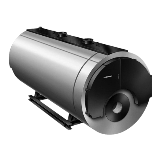
Viesmann Installation instructions for contractors Vitomax LW Type M148 Type M62 Type M64 Type M82 Type M84 Low pressure hot water boilers VITOMAX LW 5672931 GB 1/2019... -
Page 2: Safety Instructions
Work on electrical equipment may only be carried ■ out by a qualified electrician. ■ The commissioning must only be carried out by trained specialist personnel in accordance with the Viessmann operating and service instructions. Regulations to be observed ■ Pressure Equipment Directive ■ National installation regulations... -
Page 3: Table Of Contents
Preparing for installation ................ Symbols ....................■ Designation of boiler types ..............■ Intended use ..................■ Storing Viessmann shell boilers ............■ Transporting a shell boiler ..............■ Installation sequence Handling and levelling the boiler ............Recommended minimum clearances .......... -
Page 4: Installation Information Preparing For Installation
Preparing for installation Symbols The steps in connection with commissioning, inspec- Symbol Meaning tion and maintenance are found in the "Commission- Reference to other document containing ing, inspection and maintenance" section and identified further information as follows: Step in a diagram: Symbol Meaning The numbers correspond to the order in... -
Page 5: Intended Use
Use the appropriate amount of desiccant for the vol- ■ ume of the boiler. General Note ■ Store Viessmann shell boilers in closed rooms, pro- Observe the desiccant manufacturer's instructions. tected from weather influences and under dry condi- ■ Check the effectiveness of the desiccant at regular tions. -
Page 6: Transporting A Shell Boiler
Preparing for installation (cont.) Transporting a shell boiler Danger Inappropriate handling of the boiler may lead to accidents. There is a risk of injury. Only use the slinging points. Observe all the applicable regulations on accident prevention. F1/2 F1/2 Fig. 1 Options for attaching lifting gear Holes for load handling equipment ( 80 mm) -
Page 7: Installation Sequence Handling And Levelling The Boiler
Handling and levelling the boiler Recommended minimum clearances 1000 ≥ Subject to the selected control panel ≥ ≥ ≥ ≥ Tab. 1 Recommendation for dimension f Leave one boiler length (x1) of space in front of the y1/2 boiler door to extract the turbulators (if fitted) and for cleaning. -
Page 8: Anti-Vibration Supports
Handling and levelling the boiler (cont.) M84B Boiler size 6995 7545 8035 8525 8970 9410 9710 3025 3175 3300 3450 3525 3625 3675 Tab. 6 Anti-vibration supports Recommendation Installation of anti-vibration supports Use to provide vibration isolation and minimise trans- Manufacturer's installation instructions mission of structure-borne noise. - Page 9 Type M148: Moving the hinge brackets to the… (cont.) 02. Remove split pin and pull out bolt. 03. Remove eye screw. Fig. 5 04. Insert eye screw until it sits behind the joint piece. 05. Screw on the nut and slot the washer on. 06.
- Page 10 Type M148: Moving the hinge brackets to the… (cont.) 11. Remove split pin and undo nuts. 12. Pull out bolt. Fig. 8 13. Remove nuts and washers. 14. Remove eye screw. Fig. 9 15. Insert eye screw. 16. Insert bolt. 17.
- Page 11 Type M148: Moving the hinge brackets to the… (cont.) 20. Check that the boiler door is tightly sealed all the way round and adjust if required. All specified dimensions are test dimensions. Fig. 11 Fig. 12...
-
Page 12: Boiler Connections
Boiler connections M148 Boiler size Boiler flow and return For permiss. operating 6 bar 80 100 100 125 125 150 150 200 200 200 PN16 DN pressure 10 bar PN16 DN 80 100 100 125 125 150 150 200 200 200 Safety valve For permiss. - Page 13 Boiler connections (cont.) Boiler size 20 K PN25 DN Safety valve connector For permiss. operating 6 bar PN16 DN 2 x 125 pressure 10 bar PN16 DN 16 bar PN40 DN M82A Boiler size Boiler flow and return For permiss. operating pres- 6 bar PN16 DN sure...
-
Page 14: Installing The Pipework
Installing the pipework Danger Please note Risk of injury when opening pressurised boiler Unsuitable water quality can damage the boiler flue connections. shell. Do not open boiler flue connections until they Only fill the boiler with water that complies with are depressurised and have cooled down. -
Page 15: Preparing For The Control Unit Installation
Fitting the measuring and control equipment (cont.) Preparing for the control unit installation Vitocontrol boiler control unit as accessory: "Vitocontrol" technical documentation Equipment for control and limitation For boilers with Vitocontrol control panel: "Vitocontrol" technical documentation Connections on the flue gas side Danger Leaks can result in poisoning through escaping gas. -
Page 16: Fitting The Sight Glass
Connections on the flue gas side (cont.) Note on condensate drain ■ Condensate will form in the flue system. The return of this condensate must be prevented on site. Take appropriate measures, e.g. install a condensate trap. ■ Seal the condensate drain connectors (KOA) if they are not used. -
Page 17: Adjusting The Burner
Installing the burner (cont.) 3. If required, fill the annular gap between burner head and thermal insulation with heat resistant filler material (standard delivery). Note Thermal insulation blocks and loose thermal insu- lation are supplied either inside the reversing chambers of the boiler doors or inside the flame tube. - Page 18 Adjusting the burner (cont.) Boiler size Flame tube length mm 1500 1680 1860 2090 2250 2450 2650 2900 3300 3470 3700 Burner connections Max. flame head ■ Minimum flame ■ head length Combustion chamber volume Relative to flame tube length a 0.55 0.70 0.94...
- Page 19 Adjusting the burner (cont.) Boiler size Max. flame head ■ Minimum flame ■ head length Combustion chamber volume (average value) Flame tube 1.33 1.33 1.65 1.65 2.07 2.07 2.70 2.70 3.79 3.79 4.97 4.97 ■ Relative to flame tube ■ length a and reversing chamber depth b 1.58 1.58 1.93 1.93 2.38 2.38 3.07 3.07 4.24 4.24 5.49...
- Page 20 Adjusting the burner (cont.) Boiler size Combustion chamber volume (min. values) Flame tube 5.82 7.44 9.24 11.32 13.74 16.42 18.52 ■ Flame tube and reversing cham- ■ ber depth 6.37 8.08 9.99 12.17 14.71 17.52 19.72 Max. pressure drop on the flue gas side For natural gas mbar...
- Page 21 Adjusting the burner (cont.) Boiler size For natural gas mbar 11.2 12.4 14.6 ■ For EL fuel oil mbar 10.1 11.2 13.2 ■ Max. pressure drop on the flue gas side, 120 °C For natural gas mbar 11.2 12.4 14.6 ■...
- Page 22 Adjusting the burner (cont.) Boiler size For natural gas mbar 11.9 14.2 13.3 13.9 15.7 17.4 18.0 ■ For EL fuel oil mbar 10.4 12.5 11.7 10.4 10.8 10.4 ■ Fig. 17 Illustration applies to M148 Flame tube length Max. flame head diameter d1 Smooth pipe, min.
-
Page 23: Commissioning And Adjustment
(cont.) Flame tube temperature monitoring (FTM) In line with the requirements of EN 12953-3, flame tube temperature monitoring (FTM) is necessary under the following conditions: ■ Internal flame tube diameter for smooth pipes or average flame tube diameter for corrugated pipes >... - Page 24 Represented by Manufacturer Viessmann Ltd Viessmann Industriekessel Mittenwalde GmbH Hortonwood 30 Berliner Chaussee 3 TF1 7YP Telford D-15479 Mittenwalde Telephone: +441952 675000 Telephone: +49 33764 83-0 Telefax: +441952 675040 Telefax: +49 33764 83-202 www.viessmann.co.uk www.viessmann.com...
Need help?
Do you have a question about the Vitomax LW M64 and is the answer not in the manual?
Questions and answers