
Related Manuals for Trio Avionics Pro Pilot


Summary of Contents for Trio Avionics Pro Pilot
- Page 1 o Pi ilot eration n and Instal lation n Manu o Avion nics Corp poration Version n 4.1...
- Page 2 Notice: This manual uses illustrations that generally show the Pro Pilot model that mounts in a standard 3-1/8” round cutout in the instrument panel. However, all functions are duplicated in the stack mount version of the Pro Pilot. The instructions herein are valid for both systems with the following exceptions: ...
-
Page 3: Table Of Contents
Table of Contents Pro Pilot Control Head Diagram ....................7 Chapter 1 Horizontal Navigation Overview (HNAV) ..............8 GPS Requirements ..........................8 Operation ..............................8 Basic H NAV Operation Modes ....................... 8 Track Mode (TRK) ..........................9 ... - Page 4 Chapter 10 Fuel Management System Operation ..............46 Display Screens ............................. 46 Chapter 11 Configuration Menu ..................... 48 Using the Configuration Menus ......................48 Settings Available In the Configuration Menu ..................48 Minimum Airspeed Setup........................49 Trio Pro Pilot Manual 4.1...
- Page 5 Chapter 16 In Flight Adjustment of Vertical Gain ..............70 Altitude Hold Gain Tuning ........................70 Vertical Speed Gain Tuning ........................70 Chapter 17 Trim and Auto-Trim ....................71 Manual Elevator Trim ..........................71 Trio Pro Pilot Manual 4.1...
- Page 6 Alarms ..............................80 Chapter 20 Wiring Diagram ..................... 81 Chapter 21 ARINC 429 ..............Error! Bookmark not defined. ARINC 429 WIRING ..........................81 Installation 1 ............................82 Installation 2 ............................82 Trio Pro Pilot Manual 4.1...
-
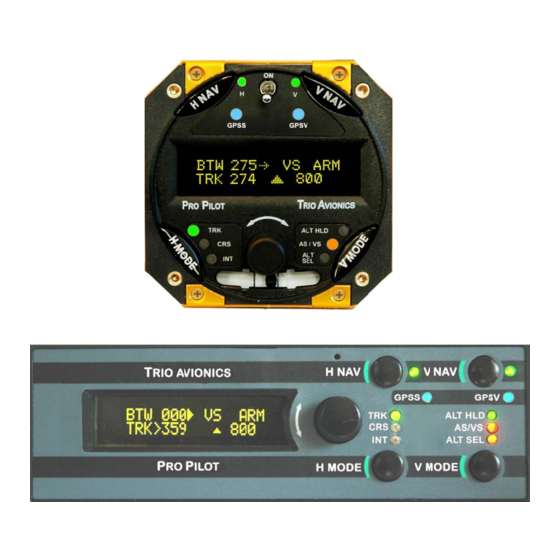
Page 7: Pro Pilot Control Head Diagram
Pro Pilot Control Head Diagram H NAV Servo V NAV Servo On/Off Switch H NAV Servo V NAV Servo On/Off On/Off Display Screen H MODE V MODE LEDs LEDs H MODE V MODE Pushbutton Pushbutton Rotary Encoder And Pushbutton Slip-Skid... -
Page 8: Chapter 1 Horizontal Navigation Overview (Hnav)
Operat tion While the e Pro Pilot is a an excellent “ “wing leveler,” ” its greatest s strength is fo llowing an ac ctive flight plan from a G PS source. -
Page 9: Track Mode (Trk)
Pilot commands CRS mode Autopilot intercepts original course Original GPS course line Hint: An alternative method of using the CRS mode is in conjunction with the Pilot Controlled Steering (PCS) mode of operation (see pages 30 & 31). Trio Pro Pilot Manual 4.1... -
Page 10: Intercept Mode (Int)
In the Intercept (INT) mode, the intercept angle to the original track may also be changed by rotating the encoder. The intercept angle will change in the direction that the encoder is rotated (as above). The Pro Pilot will automatically switch from the INT mode to the TRK mode as it crosses the intercept boundary. -
Page 11: Chapter 2 Vertical Navigation Overview (Vnav)
Vertical Navigation Overview (VNAV) The V NAV function of the Pro Pilot controls the pitch axis of the aircraft. It provides commands to the pitch servo that attaches to the elevator control system. The V NAV system uses a rate gyro, pressure sensors, airspeed sensors and accelerometers as primary references in controlling the pitch attitude of the aircraft. -
Page 12: Vertical Climb/Descent
Vertical Climb/Descent The Pro Pilot also allows the pilot to select a desired climb or descent rate (i.e. VS (vertical speed), in ft. per minute). Press the V MODE button again and: Set the desired climb or descent rate by rotating the encoder knob. -
Page 13: Chapter 3 Control And Display Overview
If no flight plan or “GOTO” waypoint has been selected in the GPS receiver, a “NO FLTPLN” message will appear and the course mode (CRS) is automatically selected (CRS LED illuminated). All servo power is initially off on power up and the Pro Pilot is disconnected from the aircraft control system. -
Page 14: H Mode And V Mode Buttons
H MOD DE and V M MODE but ttons The H MO ODE switch c controls the se election of the e TRK (track) ), CRS (cours se) and INT (i ntercept) mod des. With GPS S data presen nt, the default t mode during g power up is TRK. -
Page 15: Roll (H Nav) & Pitch (V Nav) Servo Activation
(and its pushbutton) will control when it is operated. When the arrow points to the left, the encoder will control the H MODE functions. When the arrow points to the right, the encoder will control the V MODE functions. Trio Pro Pilot Manual 4.1... -
Page 16: H Mode Encoder Functions
Rotating the encoder changes the commanded course in one-degree increments per “click” of the encoder. Rotating the encoder quickly changes the course in larger increments. Rotating the encoder counterclockwise alters the Trio Pro Pilot Manual 4.1... -
Page 17: Drift Correction (No Gps Mode Only)
If the GPS data to the Pro Pilot is unavailable, as indicated by a NO GPS warning, the encoder knob switch provides a method to turn the airplane to a new heading or stabilize the aircraft in a straight and level attitude. -
Page 18: Chapter 4 Preflight Power Up
A prefligh ht check on th he Pro Pilot at t this point wo ould be to eng gage the serv vo by pressing g the H NAV pushbutto... -
Page 19: Chapter 5 Information Fields
Power up Display When the Pro Pilot is powered on a logo display is present showing the firmware revision operating in the unit. (This can be field programmed to present a personalized screen at power on). Initial Logo Screen... -
Page 20: Normal Power Up Display, Gps Active
No H MODE LEDs will be illuminated until valid GPS data is available. Normal Power Up Display, GPS Active On power up, once the BARO SET has been performed, the Pro Pilot defaults to the H MODE display and the TRK mode of operation when valid GPS data is available. -
Page 21: Cross Track Error Field (Xtk)
TOP value is 0.00 (no offset). Groundspeed (GS) The GS (groundspeed) field indicates the aircraft speed over the ground in knots as provided by the host GPS system. This field has a maximum value of 999 knots per hour. Trio Pro Pilot Manual 4.1... -
Page 22: Estimated Time En-Route, Hh:mm (Ete)
2.5 second rate. Additionally, it will also show the status of the altitude control functions when they are engaged. This can be useful for sequentially monitoring all of the parameters put out by the GPS without having to select each parameter manually. Trio Pro Pilot Manual 4.1... -
Page 23: Gps Data Anomalies
GPS data stream is greater than 999 miles. Tracking functions are not affected by this condition. TRN? The TRN? warning is displayed in this field when the Pro Pilot detects a negative closing velocity (going away from the “TO” waypoint). -
Page 24: Chapter 6 Horizontal Operation
CRS will show the current ground track (heading) the plane was traveling when the mode is entered. The Pro Pilot will turn the plane to keep the track (TRK) and the course (CRS) the same value. Trio Pro Pilot Manual 4.1... -
Page 25: Intercept A Course (Int)
Autopilot flies INT mode to intercept GPS course Autopilot in INT As the aircraft nears the GPS course line the autopilot automatically switches to TRK Intercept Boundary Variable distance depending on speed to allow smooth intercept GPS course line Trio Pro Pilot Manual 4.1... -
Page 26: Forcing A Track Offset Position (Top)
With the advent of highly accurate GPS navigation and couOLED autopilots, aircraft are tracking more and more closely to the airway centerlines on designated airways (the Pro Pilot can easily hold the course centerline within 50 to 100 feet in smooth air). This creates the real possibility of overtaking or head-on encounters with other aircraft that are also tracking the airway centerline, especially during climb and descent when normal altitude separation is not in effect. -
Page 27: Initiating An Automatic Course Reversal
“----“(dashed lines) or may enter the NO FPLAN mode when the condition is detected. This is usually a condition that clears after another GPS sample or two is transmitted to the Pro Pilot. No pilot action is required. Normal TRK mode tracking computations are inhibited until the GPS data integrity is restored. -
Page 28: Chapter 7 Horizontal Flight Examples
One of the design features of the Pro Pilot is its ability to identify the desired track line (DTK) and fly to it regardless of the direction the airplane is heading when the autopilot is engaged. In an extreme... -
Page 29: Course Mode Example
The Pro Pilot servo is still engaged so the aircraft is being controlled in the “wing leveler” mode (aircraft roll stabilization). Without the GPS signal, the Pro Pilot solid-state gyro lacks a precise external reference and after several minutes may begin a slow change in heading due to gyro drift. -
Page 30: Intercept Mode Example
Progressing toward the DTK, as the IDS value approaches 0.0 the Pro Pilot switches automatically from the INT mode to the TRK mode when the aircraft is 1.0 miles right of the DTK. The Pro Pilot now is turning the airplane back to the right slightly and the XTK is approaching 0.00. The Pro Pilot will now re- establish the airplane back on the DTK headed directly toward the programmed waypoint. -
Page 31: Horizontal Use Of Pilot Command Steering (Pcs)
This allows the pilot to manually orient the aircraft to the desired course and re-engage the servo when the button is released. NOTE: The PCS function also works with the altitude control portion of the Pro Pilot. This is discussed in detail later in this manual. -
Page 32: Chapter 8 Vertical Operation
NOTE: This function is used only for slight changes in altitude, such as adjusting for a change in barometric pressure on a cross country flight. After adjusting the primary aircraft altimeter, the Pro Pilot may be slightly off altitude. Minor altitude adjustments will be made at about 100 fpm. If the required altitude correction is more... -
Page 33: Setting Vertical Speed (Set Vs)
NOTE: In the PCS mode the vertical rate change must be at least 200 FPM or the Pro Pilot will enter ALT HLD upon releasing the PCS (remote disconnect) button. If the rate is greater than 200 fpm it will maintain the climb/descent that it senses when the button is released. -
Page 34: Altitude Pre-Select Function (Alt Sel)
If the Pro Pilot is commanding a climb to an assigned altitude of 10,000 ft and a controller asks the pilot to temporarily hold at 6,000 ft., the pilot may press the encoder button upon reaching 6,000 ft and the aircraft will hold at that altitude. -
Page 35: Entering The Current Altitude
5 foot increments, and it should be set to be as close to the actual airfield elevation as possible, in feet. This will assure that the internal Pro Pilot system altimeter will agree closely with the aircraft altimeter that has also been corrected to airfield elevation. -
Page 36: Entering A Target Altitude
(specified in the CONFIGURATION menu) will be automatically used. The display screen will briefly show the BARO SET screen so the pilot can check the Pro Pilot altimeter against the aircraft altimeter. If the autopilot altimeter does not agree with the aircraft primary altimeter, adjust it to agree by rotating the encoder knob. -
Page 37: Pausing The Climb Example
6,500 feet. At that point, the Pro Pilot will enter the ALT HLD mode and the green ALT HLD LED will illuminate to inform the pilot that the aircraft is holding at the current altitude. The AS/VS LED and the ALT SEL LED will stop flashing, but remain illuminated (to indicate that the altitude pre-select system is “armed”). - Page 38 VS SET and ALT SEL registers (they are now “armed” and ready to execute). The Pro Pilot is now properly set for the flight. The GPS has a flight plan and the climb rate and target altitude have been entered.
-
Page 39: Vertical Use Of Pilot Command Steering
PCS AH disconnect button has been installed. As previously described, it will put the Pro Pilot into the CRS mode and track the course that the aircraft is on when the button is released. Trio Pro Pilot Manual 4.1... - Page 40 (including PCS), this should be employed only when the user has an overriding need for separate control. In this case, it will be necessary to press EACH button to disconnect the respective servo in an emergency situation. Trio Pro Pilot Manual 4.1...
-
Page 41: Chapter 9 Gpss And Gpsv Operation
ARINC 429 data stream provided by some GPS receivers and EFIS systems. When ARINC signals are available and the Pro Pilot is in the Track (TRK) mode, the autopilot follows the roll commands (GPSS) and vertical commands (GPSV) issued by the originating GPS receiver or EFIS. -
Page 42: Operation Using Certified Waas Gps Receivers
The blue GPSS LED must be illuminated (indicating a valid ARINC 429 signal is available) and the autopilot is in the Track (TRK) mode. When the GPSS option is installed the Pro Pilot (while in the TRK mode) will always default to the GPSS mode when valid data is present. -
Page 43: Approaches
Approaches The approach will normally begin with the Pro Pilot in the ALT HLD (Altitude Hold) mode, although the autopilot VS mode or externally (EFIS) generated vertical navigation may be active. When the vertical data signal becomes valid, the blue GPSV LED will blink and the autopilot will be forced automatically to the ALT HLD mode. -
Page 44: Efis Gpss And Gpsv Guidance
It is common to have a handheld backup GPS receiver for use in the event that the primary receiver fails. In the event that the primary GPS or EFIS failure, the Pro Pilot can be quickly connected to the alternate signal source by use of a simple switch. ... - Page 45 Pro Pilot commands a “bend over” maneuver. The aircraft pitches down and begins to descend. The pilot immediately retards the throttle to remain at approach speed. The Pro Pilot will now direct the aircraft to remain on the lateral/vertical descent path to the airport. Trio Pro Pilot Manual 4.1...
-
Page 46: Chapter 10 Fuel Management System Operation
Chapter 10 Fuel Management System Operation The fuel management option for the Pro Pilot allows the pilot to view multiple fuel parameters. It provides a means to accurately measure fuel flow (in gallons or liters), fuel remaining and fuel used. It employs the GPS data to compute available range and time remaining. - Page 47 If the switch is held until the countdown reaches “0”, the fuel USED display will be reset to “0” when the FUEL USED = ZERO display appears. If the button is released before the display reads FUEL USED = ZERO, the fuel USED will remain unchanged. Trio Pro Pilot Manual 4.1...
-
Page 48: Chapter 11 Configuration Menu
Chapter 11 Configuration Menu The Pro Pilot provides a quick and easy method to set up certain parameters - some that are normally only changed during installation and some that are commonly accessed in flight. These are divided into two different menus, the “Configuration Settings Menu” and the “Preferences Settings Menu”. -
Page 49: Minimum Airspeed Setup
Minimum Airspeed Setup The Pro Pilot is capable of commanding the aircraft to climb and descend at rates up to 2000 feet per minute. It is therefore necessary to assure that the system cannot stall or over-speed the aircraft, even if a pilot enters a command that would precipitate such an event. -
Page 50: Maximum Airspeed Setup
Depending upon how the servos were mounted, the proper direction of rotation of the crank arm must be assured. VNAV SERVO SET menu screen allows setting the direction of rotation of the V NAV servo. Initially the screen will appear Trio Pro Pilot Manual 4.1... -
Page 51: Initial Setup Of The Horizontal Navigation Servo
The HNAV SERVO SET procedure is complete and the encoder can now be used to select another menu screen. Once these servo directions are set, the result is stored in non-volatile memory and need not be adjusted again. Trio Pro Pilot Manual 4.1... -
Page 52: Selecting Airspeed Or Vertical Speed For Pcs
Pilot has a means whereby the users can adjust the maximum rate of turn to their personal satisfaction. When shipped, the Pro Pilot is defaulted to an “automatic” mode where the actual turn rate is automatically adjusted based on groundspeed (as measured by your GPS) to limit the bank angle to approximately 15 to 20 degrees. -
Page 53: Circle Last Waypoint Setting
If the option is set to NO, the Pro Pilot will track directly outbound from the last waypoint in a flight plan, or the GOTO waypoint. The waypoint identifier will be placed in the lower left display line upon waypoint passage and will flash for 10 seconds to indicate passage. -
Page 54: Set Default Vertical Speed Rate
The VNAV SERVO DB procedure is complete. The encoder may be used to select another screen. Autopilot Disconnect Mode The Pro Pilot is designed to accommodate either separate V NAV and H NAV remote autopilot disconnect switches or the use of a single switch to control both functions. This menu allows the selection of using either switch to separately activate the disconnect function separately for the respective axis, or have either switch activate the disconnect function for both axes. -
Page 55: Restore Defaults
Restore Defaults Several of the variables used to optimize Pro Pilot performance including the servo zero and direction settings are captured to EEPROM (non volatile memory) during initial setup. Further, tracking gains that are set for differing flight conditions are also maintained in system EEPROM. -
Page 56: Custom Startup Display Screen
There are two lines of 16 characters each available for custom programming. The screen may show a Trio Avionics logo and firmware number, but this may be changed by the user. Typically, most Pro Pilot customers place their name on the top line of the display and the aircraft model and tail number on the second line. -
Page 57: Chapter 12 Autopilot Preferences Menu
This display screen that is shown on this menu item will depend upon which display module has been installed in the Pro Pilot – OLED or LCD. The BACKLIGHT SET applies to both the LCD and OLED models and controls the backlighting of the indicators, LED’s and buttons. -
Page 58: Backlight Set And Contrast Set (Lcd Display Only)
250 miles. All distance measurements are based on nautical miles so it is recommended the host GPS receiver be programmed to measure the distance in nautical miles vs. statute miles or kilometers. Trio Pro Pilot Manual 4.1... -
Page 59: Accumulated Total Distance, Total Flight Time
3. Rotate the encoder to change the selection. 4. Press and release the H MODE button. The VNAV SERVO DB procedure is complete and the encoder can now be used to select another menu screen. Trio Pro Pilot Manual 4.1... -
Page 60: Vertical Trim Motor Speed / Direction
“up” trim and counter-clockwise should induce “down” trim. NOTE: The trim direction selection is locked if the aircraft is in a flight condition to prevent reversing this setting in flight. Ensure this setting is accomplished on the ground prior to flight. Trio Pro Pilot Manual 4.1... -
Page 61: Trim Setting Example
When adjusting the trim values it will be noted that the firmware has been designed to prevent any “crossover” in the settings. That is, the HAS can never be lower than the LAS, and vice versa. The same is true for the TL and TH settings. Trio Pro Pilot Manual 4.1... -
Page 62: Chapter 13 Fuel Preferences Menu
Adjusting K FACTOR The K FACTOR determines the accuracy of the fuel readings. The fuel flow transducers are characterized at the factory and the Pro Pilot will be set to the calibrated number, as shown here. Trio Pro Pilot Manual 4.1... -
Page 63: Setting Maximum Fuel Level
The LOW FUEL ALARM sets the fuel level at which the alarm will occur. This should typically be a value that will allow at least 45 minutes of continued flight. Setting this value to “0” will disable the alarm. Trio Pro Pilot Manual 4.1... -
Page 64: Changing Units (Gal Or Liters)
The selection is enabled by pressing the HMODE button which places an arrow next to the variable field. Rotating or pressing the ENCODER changes the selection. The selection is exited by pressing the HMODE button which erases the arrow and returns the encoder function to display selection. Fuel Sensor Connections Trio Pro Pilot Manual 4.1... -
Page 65: Chapter 14
The Pro Pilot allows the pilot to adjust three system parameters to achieve optimum horizontal navigation performance. Adjustment may be needed if the aircraft wanders more that +/- 1 or 2 degrees in the CRS mode, or in the TRK mode, if the XTK value displayed on the autopilot tends to exceed .03nm for long... -
Page 66: Vertical Navigation Gain
The V NAV system gain settings optimize the Pro Pilot altitude control system vertical tracking performance. This adjustment allows the Pro Pilot to be tailored to your individual airplane. The factory setting is a nominal value which should give good performance in most airplanes. However, to achieve best performance in your airplane the VNAV GAIN SETS adjustment should be optimized. -
Page 67: Changing Vertical Navigation Gains
5. 5. Press and release the H MODE button. The setup of the vertical navigation gains is complete and the encoder can now be used to select another menu screen. Trio Pro Pilot Manual 4.1... -
Page 68: Chapter 15 In Flight Adjustment Of Horizontal Gain
6. Observe tracking performance. If the oscillation increases return to step 2 and lower the CRS setting by two counts (original count minus one). 7. Repeat steps 2 to 6 until best tracking is obtained. Normally the Pro Pilot will hold the ground track within +/- 1 degree in smooth air You should then adjust the TRK gain for best performance while in the Track mode. -
Page 69: Setting Pull-In Gain
Setting the Overall Horizontal Servo Gain The H NAV system gain setting optimizes the overall Pro Pilot altitude control system horizontal tracking performance. This adjustment allows the Pro Pilot to be tailored to your individual airplane. The factory setting is a nominal value which should give good performance in most airplanes. -
Page 70: Chapter 16 In Flight Adjustment Of Vertical Gain
7. If the gain is set too high, there may be excessive excursions when engaging the VS mode while in a high rate of ascent/descent climb/dive. Trio Pro Pilot Manual 4.1... -
Page 71: Chapter 17 Trim And Auto-Trim
(AS/VS mode), improper trim may prevent it from achieving the proper climb or descent rate. The Pro Pilot will issue trim alerts to the pilot. If the elevator servo is equipped with the Auto-Trim option it will automatically operate the existing aircraft electric trim to remove trim errors. -
Page 72: Trim Motors
It is a common complaint that electric trim operation is often “too fast” and difficult to adjust properly. To address this, the Pro Pilot offers an effective means to adjust the speed at which the elevator trim motor runs. Adjusting the trim speed is covered in the PREFERENCES MENU – Chapter 13 The drive to the trim motor originates within the Trio Gold Standard (GS) servo. -
Page 73: Servo Installation And Setup
apter 1 Serv Servo Installatio on and Se etup The serv o unit incorpo orates importa ant safety fea atures: The internal g ears are pulle ed into the en ngaged positio on by an elec ctric solenoid. When the g ears are not engag ged, the outpu... - Page 74 In such a case the P Pro Pilot must progra mmed to reve erse the drive e signal. In the e event unusu ual pitch change...
-
Page 75: Chapter 18 The Servos
In the event the servo rotation is insufficient, the servo mechanical stops may be removed. Contact Trio Avionics if this appears to be necessary. Servo Mounting Hardware The following picture shows the electrical and mechanical installation kit that is provided for the servos. -
Page 76: Positioning The Servo Crank Arm
The serv o mounting lo ocation must b be strong and d rigid. If, for exam ple, you need d to mount the e servo on the e skin of an airplane, it will be nece essary to use e additional br racing or a “doubler”... -
Page 77: Setting Servo Override Force (Slip Clutch)
Be sure that the rod end bearing s never jam due to misal lignment as the pushrod d angle is var ried by differ rent combina ations of con ntrol system input. Push the control st tick (or contro ol wheel) in al ll four corners t o test this. - Page 78 The serv o Torque Con ntrol nut (the a adjustment n ut inside the s servo on the output shaft) sets the over rride force - th e force you w will feel at the stick when th he servo clutc ch begins to s slip.
- Page 79 Ideal level flight should occur near the 7500 center but small deviations are acceptable. Note: The Radio Shack switches specified are for reference only. Radio Shack changes their parts and suppliers often. They, or other suppliers, will have equivalent switches. Trio Pro Pilot Manual 4.1...
-
Page 80: Chapter 19 Alerts, Warnings And Alarms
NO FLT PLN – GPS is available but no flight plan or GOTO has been entered. The Pro Pilot will enter the Course (CRS) mode and will fly a pilot selected course over the ground. -
Page 81: Chapter 20 Wiring Diagram
Chapter 20 Wiring Diagram Trio Pro Pilot Manual 4.1... -
Page 82: Chapter 21 Arinc 429
ARINC 429 ARINC 429 WIRING It is recommended that the ARINC 429 and RS232 data lines be wired to the Pro Pilot through a 3 pole switch (toggle or rotary) generally available at various electronics supply companies. This will allow the selection of a backup GPS receiver in the event that the primary GPS receiver or EFIS becomes inoperative. - Page 83 This diagram clearly shows that the ARINC connections to the EFIS are not connected when the backup GPS receiver is chosen as the data source. NOTE: The diagrams above show just two examples of many possible equipment configurations. You may get additional information about other arrangements by contacting Trio Avionics. Trio Pro Pilot Manual 4.1...
Need help?
Do you have a question about the Pro Pilot and is the answer not in the manual?
Questions and answers
Do you need to connect Pitot and static lines to the unit as well if connected to a GNS650