Table of Contents
Advertisement
Advertisement
Table of Contents

Related Manuals for Trio Avionics EZ PILOT


Summary of Contents for Trio Avionics EZ PILOT
- Page 1 EZ PILOT Operation and Installation Manual Trio Avionics Corporation Rev 1.9...
- Page 2 Each homebuilt aircraft is individual in its construction, maintenance and flying characteristics. Therefore, while Trio Avionics has tested the product in a variety of aircraft, we do not represent or warrant that it is appropriate or suitable for use in your particular aircraft. Only you can make that determination and ultimately only you are responsible for its safe installation and use.
-
Page 3: Table Of Contents
4.3 Max Turn Rate selection..................15 4.4 IO = Dim or Mode? Screen..................16 4.5 Circle Last WPT? Screen ..................16 4.6 Turn Rate Display selection (EZ Pilot II only)............17 4.7 Custom Screen Setup .....................17 4.8 Software Configuration and Serial Number.............17 Ground Operation and Flight Example ..............17 5.1 Power Up and Initial Settings ..................17... - Page 4 7.7 In Flight Adjustment of Servo Neutral ..............30 7.8 System Optimization, Flight Time, Distance Counters and Totalizers....31 7.8.1 System Optimization ................31 7.8.2 Flight Time, Distance and Totalizer Counters (EZ Pilot II only)....33 7.8.2.1 Flight Time and Distance Counters .........33 7.8.2.2 Flight Time and Distance Totalizer Displays......34 Electrical Requirements ....................34...
-
Page 5: Introduction
While the EZ Pilot is inherently simple to use, this manual will serve as a guide to understanding its basic functions and employing its many advanced features. The EZ Pilot is so feature-rich that mastering it all might seem intimidating at first. -
Page 6: General Information
The EZ Pilot is a single axis autopilot that controls the roll axis for aircraft attitude correction (wing leveling) and provides area navigation using signals provided by an external GPS receiver. It is composed of two units, the control/display unit and the roll servo. -
Page 7: Course Mode (Crs)
In both the CRS and INT modes the ground track to be followed may be selected by the pilot, using either the L/R switch or the PCS steering mode of operation The EZ Pilot will automatically switch from the INT mode to the TRK mode as it nears the intercept boundary. -
Page 8: Control And Display Unit
Please paragraph 3.2.12 for operation instructions for this feature. Also, the MODE switch function may be connected to an external switch (in lieu of the display dimming function) to provide a remote method of changing the EZ Pilot mode setting. See paragraph 4.0 for additional details. -
Page 9: Servo Power Switch
INT mode the pilot may transition to the TRK mode, or through TRK to CRS mode, by pressing the MODE switch.) 3.1.3 Servo Power Switch The servo power switch controls power application to the EZ Pilot servo. When the SERVO LED is unlighted servo power is interrupted. This power interruption disconnects the EZ Pilot completely from the control system. -
Page 10: Left Or Right (L/R) Switch
6 - Setup Screen Entry If the DISPLAY button is pressed when power is applied, the EZ Pilot will go into the SETUP mode function. In this mode the following screens and operating parameters can be changed: •... -
Page 11: Display Information
If the GPS data to the EZ Pilot is unavailable, as indicated by a NO GPS warning, the L-R switch provides a method to turn the airplane to a new heading or stabilize the aircraft in a straight and level attitude. -
Page 12: Gps Active, Normal Power-Up Display
In the event the GPS signal is lost during normal area navigation the "NO GPS" screen will be made active and the EZ Pilot will go into the wing leveler mode following a “straight and level” course on the last commanded groundtrack. In this mode, manual corrections to the dead reckoning track can be made using the electronic trim feature. -
Page 13: Trk (Groundtrack Field)
or left of the desired track (DTK). The maximum value in this field is 9.99 miles. A positioning symbol, immediately preceding the numerical data, indicates the "fly to" direction required to null this error. If this symbol has its apex to the left (<), the autopilot will fly to the left to eliminate the error. -
Page 14: Ete (Estimated Time En-Route, Mm:ss)
[------- ™™----] pilot when this field is selected. On the EZ Pilot II the pilot has the setup option of using either the small rate of turn display, or the large rate of turn display. The limit on this rate is approximately ±4.5 degrees per second full scale. -
Page 15: Trn
The TRN? warning is displayed in this TRK 025 TRN? field when the EZ Pilot detects a negative closing velocity (going away from the “TO” waypoint). This usually occurs when a waypoint greater than ± 90 degrees from the current waypoint is selected. No pilot action is required. -
Page 16: Int (Intercept) Mode
To help avoid such encounters, the EZ Pilot incorporates a feature heretofore found only in high end Flight Management Systems – Track Offset Position (TOP). -
Page 17: Automatic Course Reversal
The TOP function is deactivated by setting the TOP field to 0.0 using the L-R switch, or by simply cycling power to the EZ Pilot using the POWER switch. When activated, note that the arrow on BTW♦175 TOP>0.3 the XTK changes from an outline arrow TRK>176... -
Page 18: Variable Display Field - Upper Line
6. Selection to circle a last waypoint or proceed outbound from a last waypoint. 7. Selection of a large or small format rate electronic rate of turn indicator (EZ Pilot II only) 8. Setup of a custom startup screen 9. -
Page 19: Contrast Setting (Lcd Model Only)
In faster aircraft this steeper bank may be uncomfortable to some pilots and, indeed, may exceed the capability of an altitude hold system to maintain altitude properly in the turn. To remedy this, the EZ Pilot has a means whereby the users can adjust the maximum rate of turn to their personal satisfaction. -
Page 20: Io = Dim Or Mode? Screen
10 seconds to indicate passage. If the option is set to YES, the EZ pilot will turn the aircraft to effectively “home” to this last waypoint. Both modes remain in their respective states until the mode of the EZ Pilot... -
Page 21: Turn Rate Display Selection (Ez Pilot Ii Only)
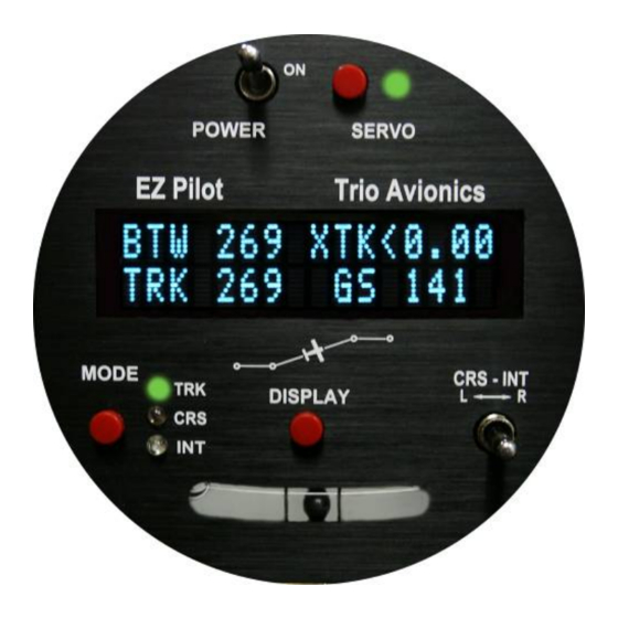
Power Up and Initial Settings On power up the EZ Pilot will display the logo screen. Note that the TRK LED is illuminated and the SERVO power is off (SERVO LED is not illuminated). The aircraft roll control (ailerons) should... - Page 22 A preflight check on the EZ Pilot at this point would be to engage the servo by pressing the SERVO POWER pushbutton momentarily and noting that the SERVO POWER LED illuminates.
-
Page 23: Flying To A Courseline Or Goto Waypoint
Note that the SERVO LED is now on and the autopilot has control of the aircraft. One of the design features of the EZ Pilot is its ability to find the desired course (DTK) and track to it regardless of where the airplane is heading when the autopilot is engaged. In an extreme... -
Page 24: Crs Mode Operation
7 seconds without signal the EZ Pilot displays the NO GPS message. Since the EZ Pilot is no longer able to provide the navigation function, the L-R switch can be used to control the aircraft turn rate. The EZ Pilot servo is still engaged so the aircraft is being controlled in the “wing leveler” mode (aircraft roll stabilization). -
Page 25: Int Mode Operation
2. Going directly back to the TRK mode causes the EZ Pilot to more gradually curve back to the DTK. Alternatively, the pilot may choose to enter a “Direct” command into the host GPS system, thus proceeding directly to the next waypoint rather than intercepting the original desired track (DTK). - Page 26 When the remote button is pressed initially, the Servo LED will extinguish normally, and the servo will disconnect, giving the pilot full control of the aircraft. After the button is held down for 5 seconds or more, the Servo LED will begin to flash, indicating that the servo will re-engage when the button is released.
-
Page 27: Installing The Control Head
If you do not get a proper display (once your GPS is turned on and has a clear view of the sky) check the wiring connections between the GPS unit and the EZ Pilot. The signal input requires a data input and a ground, and these must be wired as shown in the wiring diagram (Section 8.6). - Page 28 NO GPS will be displayed until this is accomplished. Some other GPS receivers output only a few of the parameters needed for autopilot operation which the EZ pilot will recognize by entering the NO FPLAN mode. Other receivers (KING KLN-XX models, for example) will not output a valid data link signal until a certain groundspeed (usually a few knots or more) has been attained.
-
Page 29: Servo
• The servo is engaged and disengaged by pressing the SERVO button on the EZ Pilot control head. There is also a provision to accommodate a remote SERVO DISCONNECT switch on the control stick (or other remote location). Installation of a... -
Page 30: Servo Mounting Hardware
Changing the crank arm mounting by 180 degrees will essentially reverse the direction of travel for the servo arm. In such a case the EZ Pilot control head must be programmed to reverse the drive signal. -
Page 31: Selecting A Site For The Servo
7.3 Selecting a Site for the Servo For most aircraft, it’s relatively easy to find a suitable site for locating the crank arm servo. The length of the pushrod and, to some extent, the angle it makes with the driven element are user selectable. -
Page 32: Install The Servo Pushrod
(see Note). Don’t worry about being exactly correct – the servo neutral position will later be positioned (on the ground and in flight) using the electronics in the EZ Pilot control head. Note: The neutral position for your ailerons will be dependent upon how precisely your flying surfaces are aligned. -
Page 33: Adjustment Of Servo Rotation Direction And Servo Neutral
The EZ Pilot incorporates an electronic method to “zero” the servo once it has been properly installed. This setting is then stored in the autopilot permanent memory, thus eliminating the need to perform repetitive mechanical adjustments to achieve an accurate neutral position. -
Page 34: Servo Direction Reversal
7.6.3 Servo Direction Reversal To reverse servo rotation, press the MODE switch one time until the arrow cursor points at the NORM to the right of the SERVO readout. Move the L-R switch either direction to change the NORM in line 2 to read REV; then, press the mode switch several times to scroll through the remaining setup screens and return to the NO GPS display. -
Page 35: System Optimization, Flight Time, Distance Counters And Totalizers
Press the “DISPLAY” button and hold it in for 6 seconds. After six seconds the flight time (EZ Pilot II only) and /or calibration screens will be displayed. If the flight time screen is displayed, momentarily press the DISPLAY button until the below screen is on the display... - Page 36 7. Observe tracking performance. If the oscillation increases return to step 3 and lower the FINE CRS QLT setting by two counts (original count minus one) 8. Repeat steps 3 to 7 until best tracking is obtained. Normally the EZ Pilot will hold the groundtrack within +/- 1 degree in smooth air You should then adjust the FINE TRK QLT for best performance while in the Track mode.
-
Page 37: Flight Time, Distance And Totalizer Counters (Ez Pilot Ii Only)
7.8.2 Flight Time, Distance and Totalizer Counters (EZ Pilot II only) The EZ Pilot II contains flight time and flight and distance counters and Flight time and distance totalizers on two screens within the calibration displays menu. 7.8.2.1 Flight Time and Distance Counters... -
Page 38: Flight Time And Distance Totalizer Displays
8.1 Primary Input Power The EZ Pilot requires an input power on pin 13 of 10 to 14 VDC at 1 amp and servo power on pin 19 or 18 of approximately 1 amp. The EZ Pilot is internally fused and requires wire from a circuit breaker capable of supplying approximately 3 amps. -
Page 39: Wiring Diagram
These signals should be run in a shielded cable along with the appropriate ground signal. Ground the cable shield at the EZ Pilot end and to a servo mounting screw at the servo end of the shield. Power ground wiring should originate at the airframe ground point. -
Page 40: Glossary Of Terms
Specification for data transfer protocol between systems SPD? Speed tolerance error indicator Track Offset Position Vacuum Florescent Display – The EZ Pilot display Wing Leveler Holds wings level without reference to navigation signals "TO" waypoint identifier Cross Track Error – measure of deviation from DTK 10.0...
Need help?
Do you have a question about the EZ PILOT and is the answer not in the manual?
Questions and answers