
Related Manuals for IMC CANSAS


Summary of Contents for IMC CANSAS
- Page 1 CANSAS Doc. Rev. 2.0 R1 - 2016-05-24 Getting Started © 2016 imc Meßsysteme GmbH imc Meßsysteme GmbH • Voltastraße 5 • 13355 Berlin • Germany...
- Page 2 GPL Sources Some components of our hardware use software, that is licensed under GNU General Public License (GPL). If you would like a copy of the GPL source code contained in this product please contact the imc Hotline. © 2016 imc Meßsysteme GmbH...
-
Page 3: Table Of Contents
3.3.6 Modules with Autosport (AS) terminals ..................54 3.3.7 CANSAS-IGN ..........................56 3.3.8 CANSAS-SENT ..........................57 3.3.9 µ-CANSAS-H-B1 ..........................58 4 Last Changes ....................59 Index ......................... 60 © 2016 imc Meßsysteme GmbH imc CANSAS - Getting Started, Doc. Rev. 2.0 R1 - 2016-05-24... -
Page 4: General
If you contact us you would help us, if you know the serial number of your devices and the version info of the software. This documentation should also be on hand. Thank you! © 2016 imc Meßsysteme GmbH imc CANSAS - Getting Started, Doc. Rev. 2.0 R1 - 2016-05-24... -
Page 5: Product Improvement / Change Requests
Products not satisfying these requirements may only be used with special approval of the regulating body in the country where operated. All signal lines connected to imc CANSAS must be shielded and the shielding must be grounded. Note The EMC tests were carried out using shielded and grounded input and output cables with the exception of the power cord. - Page 6 The measurement system has been carefully designed, assembled and routinely tested in accordance with the safety regulations specified in the included certificate of conformity and has left imc in perfect operating condition. To maintain this condition and to ensure continued danger-free operation, the user should pay particular attention to the remarks and warnings made in this chapter.
-
Page 7: Important Information
The device has been carefully designed, assembled and routinely tested in accordance with the pertinent safety regulations and has left imc in perfect operating condition. To maintain this condition and to ensure continued danger-free operation, the user should pay particular attention to the remarks and warnings made in this chapter. - Page 8 Note that a imc CANSAS module must be configured before being taken into operation! 1.2.1.5 Guarantee Each device is subjected to a 24-hour "burn-in" before leaving imc. This procedure is capable of recognizing almost all cases of early failure. This does not, however, guarantee that a component will not fail after longer operation.
- Page 9 Always arrange your cables and signal leads in a safe fashion. Think prevention! Never connect or disconnect signal leads during thunderstorms. © 2016 imc Meßsysteme GmbH imc CANSAS - Getting Started, Doc. Rev. 2.0 R1 - 2016-05-24...
- Page 10 General 1.2.1.7 General Safety Certain basic rules of safety are always to be followed, even with 'safe' devices such as imc CANSAS. Unintended and/ or inappropriate usage of the device can be dangerous for the operator and/or surrounding persons and, in the worst case, can damage the test object or imc CANSAS itself. We strongly discourage the user from making any modifications to the measurement system whatsoever.
-
Page 11: System Requirements
Windows Vista (32 Bit) as of SP1 Windows XP (32 Bit) as of SP3 Minimum requirements for the PC 1 GB RAM 100 MB free hard disk drive (NTFS format) © 2016 imc Meßsysteme GmbH imc CANSAS - Getting Started, Doc. Rev. 2.0 R1 - 2016-05-24... -
Page 12: Startup
The functionality is provided by the manufacturer of the interface card or adapter. Please check the internet page of the manufacturer for driver updates also. At present for Windows 64 bit, interfaces for imc CANSAS are supported by imc and KVASER. © 2016 imc Meßsysteme GmbH... -
Page 13: Kvaser Interface Cards
Interface cards 2.1.1 KVASER interface cards imc CANSAS works with the KVASER -driver without problems for XP 32/64, Win7-32/64 and for Win 8/8.1. After the driver has been installed, the computer must be re-started. Some FAQs about this subject can... -
Page 14: Imc Interface Adapter
Startup 2.1.2 imc interface adapter The imc CANSAS configuration software can use a USB adapter by imc for access to the CAN-Bus. Installation of the driver is accomplished by means of Window's Plug’n’Play functionality. The driver is located under \Driver\Imc on the CD. The interface can be used on all Windows operating systems which are USB-supported. - Page 15 If problems arise despite proper installation of the USB-driver as described, you can get a readout of the version via Settings / Control panel /imc CAN/USB. This is useful, for instance, in order to inform our hotline of the problem.
-
Page 16: Faq For The Kvaser Interface
How you set up the Kvaser Leaf SemiPro HS interface for the imc CANSAS is described in the FAQ below. · I ordered an imc USB Interface and I received a Kvaser Leaf SemiPro HS Interface for my imc CANSAS. Is this a mistake? No. -
Page 17: Installation Of Imc Cansas Software
Interface cards 2.2 Installation of imc CANSAS software The software included for installing the imc CANSAS-module is on CD-ROM. The software is started by running the file "Setup.exe". The supported operating systems are listed here The installation process includes updating of the following drivers: ·... - Page 18 Startup The next dialog is for selecting program components to install. The imc CANSAS Program files must be retained as active since they are essential for configuring imc CANSAS. The component Report Export formats only needs to be installed if a imc CANSAS report on module configurations is to be saved in an extraneous format, such as in the form of an Excel file.
- Page 19 The last dialog announces successful installation. If, however, the "Common Controls" are too old for the imc CANSAS software, the installation continues with the Microsoft installation of the common controls. This may make it necessary to reboot the computer.
-
Page 20: Attachment Mechanism Of The Imc Cansasfit Modules
When used in a controlled, dry environment, this should cause no problems. In order for an imc CANSASfit module (or a group of modules attached in a substack) to be protected against foreign objects and moisture, please take the following steps:... - Page 21 CAN- CAN- CAN- Interface Interface Interface CAN-Bus passive CAN-Interface Hinweis The maximum amount of modules of a substack of modules should not pass 10! © 2016 imc Meßsysteme GmbH imc CANSAS - Getting Started, Doc. Rev. 2.0 R1 - 2016-05-24...
-
Page 22: Connections
2.4.4 Checking connections A dialog called from the menu item in the imc CANSAS interface's ‘EXTRAS’ menu lets you make settings for the CAN-Bus access and for interface parameters. Details are available in Chapter "Operation" - Extras/ Interface and in the booklet or diskette about the interface-card. -
Page 23: Pin Configuration
Hardware Version 2: Valid for all UNI8, P8, DO16R, C8 and all -L- modules. For all other modules, please check in the software under General/ Version/ Hardware whether this is the version. Generally it only is for modules shipped since late-2003. © 2016 imc Meßsysteme GmbH imc CANSAS - Getting Started, Doc. Rev. 2.0 R1 - 2016-05-24... - Page 24 3.1.1.2 Notes for the use of CANcabs Problem: Pins 4 and 9 are used in imc CANSAS for Reset and OneWire EEPROM. When a CANcabs extra cable from any of the companies Vector, dSPACE or KVASER is used, it results in duplicate pin assignment, since these pins are also used in those cases.
- Page 25 RL: reserved, may not be connected 3.1.1.3 Specification of components used In imc CANSAS, the following components are used for the CAN-connection. Use this as a reference for the purpose of especially critical applications, e.g. in connection with bit-timing. CAN-Controller:...
-
Page 26: 19" Rack
RACKs are equipped with an integrated slot recognition. There is an EPROM for each slot integrated in the Backplane of the RACK. The imc CANSAS software is able to interpret the content of this EPROM. Using multiple RACKs it is possible to define for each RACK a level number ("X", see slot: level (tier) / position). -
Page 27: Cansas-Sl With Lemo
3.1.3 CANSAS-SL with LEMO The following overview shows the pin configuration of the CAN-bus sockets (CAN IN and CAN OUT) of the imc CANSAS-SL housings. The differences to the standard imc CANSAS modules are described here. 3.1.3.1 CAN-Bus pin configuration and contact wiring 10-pin LEMO (HGA.1B.310) -
Page 28: Μ-Cansas With Autosport Or Lemo
Pin configuration 3.1.4 µ-CANSAS with Autosport or LEMO Below is the pin configuration of the imc µ-CANSAS modules’ CAN-Bus connector. Connections of -AS modules are made via 6-pin Autosport terminals of the type AS208-35SA (CAN IN) and AS208-35PA (CAN OUT). Special tools exist for the purpose of assembling the Autosport connectors. More information is available here. - Page 29 Signal Use in imc CANSAS +CAN_SUPPLY dominant high bus imc CANSAS-specific: line + imc CANSAS supply +9…+50 V. The module is supplied via the pins +CAN_SUPPLY and –SUPPLY. -SUPPLY imc CANSAS-specific: - imc CANSAS power supply (minus contact: 0V). CAN_HIGH...
- Page 30 3.1.4.2 Cables for µ-CANSAS For connecting your imc µ-CANSAS modules, pre-configured cables are available. The connection schematics below are to help you select the necessary components. Like the imc µ-CANSAS modules, the imc µ-CANSAS cables are designed for use in extreme temperature conditions.
- Page 31 Type 2 CAN connection cable: From 6-pin female AS608-35SA on device side to 9-pin DSUB-socket and 4- pin Phoenix socket; shielded, 1,5 m. Temperature range: -15 °C … 60 °C. For direct connection of imc µ- CANSAS-xx-AS(T) and µ-HUB4-AS (µimc CANSAS connected via male CAN-connector, if connected at CAN IN socket [right side]) to the imc CAN-interface and an external power supply.
- Page 32 Type 1 CAN connection cable: From 6-pin female AS608-35SA on device side to 9-pin DSUB-socket; shielded, 1,5 m. Temperature range: -40 °C … 120 °C. For direct connection of imc µ-CANSAS-x1-AST, imc µ-CANSAS-x4-AS(T) and µ-HUB4-AS (imc µ-CANSAS connected via male CAN-terminal, if connected at CAN IN socket [right side]) to the imc CAN-interface, if the module is supplied via the CAN-Bus.
-
Page 33: Cansasfit With Lemo
Note · Per default imc CANSASfit modules come without an internal terminator resistor. · Pin 3 and pin 4 are absolutely necessary for transmission on the CAN-Bus, as well as the CAN- Bus ground. According to specifications, the differential signals require a reference, for which reason a CAN-Bus ground connection is also needed. -
Page 34: Power Supply
· The connectors at the Phoenix-terminal and those for the CAN-bus are not connected internally but are separated from each other by diodes. Therefore, make sure that the imc CANSAS module is supplied with power via only one of the two possible ways! ·... -
Page 35: Cansas-Sl
· The connectors at the 6-pin LEMO socket and those for the CAN-bus are not connected internally but are separated from each other by diodes. Therefore, make sure that the imc CANSAS module is supplied with power via only one of the two possible ways! ·... -
Page 36: Μ-Cansas
Also make note of the information presented above on the CAN-Bus’ wiring. · imc devices' CAN-Bus terminals are not rated for the supply of imc CANSAS modules, but under certain circumstances they can be modified at imc for this purpose. If interested, please contact our Customer Support. -
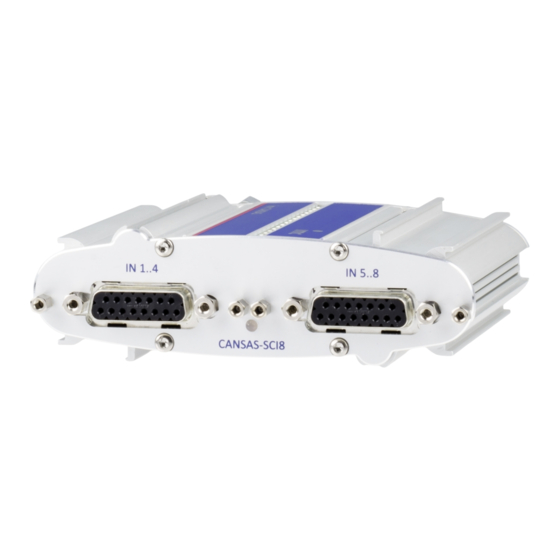
Page 37: Signal Connection
In such cases, the values of the technical specifications may not be reached. 3.3.1 Standard modules with DSUB-15 The illustration below shows the view of the imc CANSAS module from the inputs' side: Note Don't loosen screws crossed out in red! These secure the device housing. - Page 38 2. Audible click when the lid snaps in the front of the DSUB pod 3. Insert the bend protection 4. The pressure nut must be screwed back on 5. The lid screws can be tightened © 2016 imc Meßsysteme GmbH imc CANSAS - Getting Started, Doc. Rev. 2.0 R1 - 2016-05-24...
- Page 39 []: if SEN SUPPLY with ±15V option, then this pin = -15V []:1/4 Bridge with UNI8, DCB8 * if SEN SUPPLY with ±15V option, then this pin 6 = reference ** not CAN/C8 © 2016 imc Meßsysteme GmbH imc CANSAS - Getting Started, Doc. Rev. 2.0 R1 - 2016-05-24...
- Page 40 ** OPDRN is reserved and is not to be connected. ***ACC/DSUB-REL4 should only be used as replacement for CAN/DSUB-STD (RELAIS). Note that OFF and ON are swapped. © 2016 imc Meßsysteme GmbH imc CANSAS - Getting Started, Doc. Rev. 2.0 R1 - 2016-05-24...
- Page 41 Signal connection 3.3.1.2 TEDS plugs ** not for imc CANSAS © 2016 imc Meßsysteme GmbH imc CANSAS - Getting Started, Doc. Rev. 2.0 R1 - 2016-05-24...
- Page 42 CHASSIS CHASSIS CHASSIS CHASSIS CHASSIS Index at CON1 only For CAN/DSUB-STD(RELAIS), ACC/DSUB-REL4 could be used as replacement. Note that OFF and ON are swapped. © 2016 imc Meßsysteme GmbH imc CANSAS - Getting Started, Doc. Rev. 2.0 R1 - 2016-05-24...
-
Page 43: Modules With Dsub-9 Connectors
* - Sensor supply voltages available with optional sensor supply module imc CANSAS -L-DO8R-V, -L-DI16-V, -L-DAC8-V, -L-PWM8-V ITT VEAM -L-DO8R-V -L-DI16-V -L-DAC8-V L-PWM8-V PWM Open Drain PWM TTL CHASSIS CHASSIS CHASSIS CHASSIS © 2016 imc Meßsysteme GmbH imc CANSAS - Getting Started, Doc. Rev. 2.0 R1 - 2016-05-24... -
Page 44: Modules With Lemo Connectors
Pin configuration 3.3.4 Modules with LEMO connectors The imc CANSAS modules of the housing model SL which are equipped with LEMO connectors have certain limitations regarding measurement possibilities. The exact limitations are stated in the general technical specs of the respective module in the chapter General technical specs. With these modules, a separate LEMO connector is available for each channel. - Page 45 +IN_60V with divider (MR: 2 to 60 V) +SUPPLY +SUPPLY -SUPPLY -SUPPLY (GND) n.c. n.c. -SENSE +IN_1V without divider +SENSE (MR: 0.1 to 1 V) © 2016 imc Meßsysteme GmbH imc CANSAS - Getting Started, Doc. Rev. 2.0 R1 - 2016-05-24...
- Page 46 -IN4 / Ni -IN8 / Ni view on the LEMO.2P socket LEMO Pin Signal 1 and 5 / Material +IN / NiCr -IN / Ni © 2016 imc Meßsysteme GmbH imc CANSAS - Getting Started, Doc. Rev. 2.0 R1 - 2016-05-24...
-
Page 47: Modules With Phoenix Terminal Block
+IN 15 -IN 7 -IN 15 +IN 8 +IN 16 -IN 8 -IN 16 LEVEL 1 LEVEL 1 DGND DGND CHASSIS CHASSIS CHASSIS CHASSIS © 2016 imc Meßsysteme GmbH imc CANSAS - Getting Started, Doc. Rev. 2.0 R1 - 2016-05-24... - Page 48 Supply * 5 VDC 5 VDC Supply * Ground * Ground * CHASSIS CHASSIS CHASSIS CHASSIS * updated pin configuration, starting from July 2011 © 2016 imc Meßsysteme GmbH imc CANSAS - Getting Started, Doc. Rev. 2.0 R1 - 2016-05-24...
- Page 49 5 V 2 GND 1 LCOM 1/CHASSIS LCOM 2/CHASSIS GND 2 3.3.5.5 CANSAS-L-DO8R-Ph connection socket OFF1 OFF2 OFF3 OFF4 OFF5 OFF6 OFF7 OFF8 CHASSIS CHASSIS CHASSIS © 2016 imc Meßsysteme GmbH imc CANSAS - Getting Started, Doc. Rev. 2.0 R1 - 2016-05-24...
- Page 50 Note · There is a possibility for certain function configurations to cause an electrostatic discharge (ESD) directly at the connection terminals. This can lead to asynchronous operation (crash) of the imc CANSAS-L-HVCI8. This will not cause any damage. · A brief interruption of the power supply causes the module to restart (correctly).
- Page 51 Pin configuration of the Phoenix strip terminal for imc µ-CANSAS-T1-AS Phoenix MPT0,5/8 Signal reserved -IN_COM reserved 8-pin Phoenix strip terminal reserved reserved 8-Pin Phoenix MPT0,5/8 reserved Contact inserts with screw connections reserved © 2016 imc Meßsysteme GmbH imc CANSAS - Getting Started, Doc. Rev. 2.0 R1 - 2016-05-24...
- Page 52 Pin configuration 3.3.5.8.1 Connection instructions Within a imc µ-CANSAS module there is a Phoenix strip terminal (model: MPT0.5/8) for connecting sig- nals. This strip terminal is located on a connector junction which can be detached from the front of the module.
- Page 53 Step 8: Once the housing face is placed flush on the housing, the module can be closed tight with the Torx screws. © 2016 imc Meßsysteme GmbH imc CANSAS - Getting Started, Doc. Rev. 2.0 R1 - 2016-05-24...
-
Page 54: Modules With Autosport (As) Terminals
Pin configuration 3.3.6 Modules with Autosport (AS) terminals Pin configuration of the Autosport terminal type AS212-35SN for imc µ-CANSAS-V4-AS AS212-35SN Signal +IN_60V_CH1 (MB: 2..60V) +IN_1V_CH1 (MB: 0,1..1V) +SUPPLY_CH1 +SUPPLY_CH2 -SUPPLY_CH2 +SUPPLY_CH3 n.c. -SUPPLY_CH4 +IN_60V_CH4 (MB: 2 .. 60V) +IN_1V_CH4 (MB: 0,1 .. 1V) +IN_60V_CH3 (MB: 2 .. - Page 55 Signal connection Pin configuration of the Autosport terminal type AS214-35SN for imc µ-CANSAS-B4-AS AS214-35SN Signal +Sense_CH4 +SUPPLY_CH4 HB_CH4 -IN_COM_CH4 HB_CH3 -IN_COM_CH3 n.c. n.c. HB_CH2 -IN_COM_CH2 -IN_COM_CH1 HB_CH1 +Sense_CH1 +SUPPLY_CH1 +Sense_CH2 +SUPPLY_CH2 +Sense_CH3 +SUPPLY_CH3 -SUPPLY_CH3 -SUPPLY_CH4 n.c. +IN_1V_CH4 +IN_1V_CH3 +IN_1V_CH2 37-pin Autosport terminal n.c.
-
Page 56: Cansas-Ign
10 Digital Ground 0 V 11 Digital Ground 0 V 12 Digital Ground 0 V 13 Ground 0 V 14 not connected 15 Analog Ground 0 V © 2016 imc Meßsysteme GmbH imc CANSAS - Getting Started, Doc. Rev. 2.0 R1 - 2016-05-24... -
Page 57: Cansas-Sent
SIG Signal Input 7 GND Input 3 GND Input 7 V Supply (5 V) Input 4 V Supply (5 V) Input 8 Not used Not used © 2016 imc Meßsysteme GmbH imc CANSAS - Getting Started, Doc. Rev. 2.0 R1 - 2016-05-24... -
Page 58: Μ-Cansas-H-B1
12 -SENSE Note Each terminal block will be coded by imc ex-factory in a way that each block can only be connected to the corresponding plug (female). This makes sure that a incorrect connection is not possible at all. The coding of this terminal block is done by imc! ©... -
Page 59: Last Changes
Amendments and bug-fix in Doc. Version 1.9 Chapter Amendments - status 2014-06-20 ITT VEAM pin modules with special pin configuration are not mentioned in this manual any more configuration © 2016 imc Meßsysteme GmbH imc CANSAS - Getting Started, Doc. Rev. 2.0 R1 - 2016-05-24... -
Page 60: Index
DSUB-15 CAN-Bus CAN-Bus at SL housings connection for the PC ElektroG connection to CANSAS CANboardXL CANboardXL pxi- CAN-Bus cable FCC-Note cable at SL housings © 2016 imc Meßsysteme GmbH imc CANSAS - Getting Started, Doc. Rev. 2.0 R1 - 2016-05-24... - Page 61 KVASER µ-CANSAS KVASER (FAQ) SL housing Product improvement PWM8 L-DI16-Ph ITT VEAM terminal Phoenix terminal block LEMO connector pin configuration Quality Management © 2016 imc Meßsysteme GmbH imc CANSAS - Getting Started, Doc. Rev. 2.0 R1 - 2016-05-24...
- Page 62 HCI8 HVCI8 Terminal IGN transporting CANSAS troubleshooting UNI8 LEMO plug Vector Warranty WEEE Restriction of Hazardous Substances wiring CAN-Bus CAN-Bus at SL housings © 2016 imc Meßsysteme GmbH imc CANSAS - Getting Started, Doc. Rev. 2.0 R1 - 2016-05-24...
Need help?
Do you have a question about the CANSAS and is the answer not in the manual?
Questions and answers