
Subscribe to Our Youtube Channel
Related Manuals for IMC CAEMAX DX


Summary of Contents for IMC CAEMAX DX
- Page 1 Manual Telemetry System CAEMAX Technologie GmbH Phone: 089 – 61 30 49 - 0 Bunzlauer Platz 1 info@caemax.de Fax: 089 – 61 30 49 - 57 D-80992 München www.caemax.de...
-
Page 2: Table Of Contents
Telemetry System Manual Vers. 2.7 Table of Contents Introduction ......................... 5 Abbreviations ..........................5 System Overview .........................5 Application ............................6 Packing ............................7 Technical Components ....................8 Signal Conditioning Transmitter (D -SCT) ...................8 2.1.1 Voltage Inputs for Small Level Signal (Strain Gauges, Thermo couple, etc.) ........9 2.1.2 Inputs for high-level signal (voltage measurement)................ - Page 3 Telemetry System Manual Vers. 2.7 3.10.2 Configure Online Display ........................40 3.10.3 Start and Stop Measurement ......................41 3.10.4 Start Measurement Automatically (Auto Measure Start) ..............42 Configuration Menu ..................... 43 Menu tree ..........................43 Settings............................45 Menu: Device Base RCI ......................... 45 4.2.1 Menu: Device ...
- Page 4 Telemetry System Manual Vers. 2.7 Custom Systems ....................75 RPM measurement option......................75 8.1.1 System Overview ..........................75 8.1.2 Terminal Assignment of modified RCI ....................75 8.1.3 Incremental Angle Sensor ........................76 8.1.4 Operating Instructions ......................... 77 8.1.5 Instructions for Commissioning and Maintenance ................77 Settings............................
-
Page 5: Introduction
Telemetry System Manual Vers. 2.7 Introduction We compliment you on the purchase of your new digital multi-channel telemetry system D The D is a state-of-the-art telemetry system for measurement technology. We recommend you to acquaint yourself with the basics of the system before installing it or putting it into operation. -
Page 6: Application
Telemetry System Manual Vers. 2.7 Figure 1: System Overview Application The telemetry system D can be used to receive, transfer and process electronically measured variables. No liability will be accepted by the manufacturer when the system is not used as intended. The system is designed for the signal processing of strain gauges, thermo couples (- 200+1000°C) and analog voltage inputs (0...... -
Page 7: Packing
Telemetry System Manual Vers. 2.7 Packing The complete system will be delivered in one case. Contents: Receiver Control Interface (RCI) Signal Conditioning Transmitter (SCT) Ethernet cable Rod antennas Power supply Manual Optional: planar antennas Optional: ring stator Optional: assembly material for rotor application Figure 2: Case Contents... -
Page 8: Technical Components
Telemetry System Manual Vers. 2.7 Technical Components Signal Conditioning Transmitter (D -SCT) Figure 3: Rotor Electronics (SCT) RF- transmitter: Freely programmable channel in the 868 MHz ISM band (optionally 2.4GHz) Transmission power: Max. + 10dBm, will be adjusted as required and according to the national restrictions (LBT procedures included) Data transfer: Package transfer with error detection... -
Page 9: Voltage Inputs For Small Level Signal (Strain Gauges, Thermo Couple, Etc.)
Telemetry System Manual Vers. 2.7 2.1.1 Voltage Inputs for Small Level Signal (Strain Gauges, Thermo couple, etc.) Either two differential voltage inputs to connect up to two full bridges or thermocouples, or to connect four half-bridge inputs with internal half-bridge completion. Input ranges: ±... -
Page 10: Additional Channels For Sct Temperature And Supply Voltage
Telemetry System Manual Vers. 2.7 2.1.3 Additional Channels for SCT Temperature and Supply Voltage The extra channel of the SCT for temperature is also used as a reference for thermo couple sensors. -30°C – +100°C Measurement range: Resolution: 12 bit Sampling rate: 25 Hz The internal measurement of supply voltage can be used to monitor the battery voltage or to... -
Page 11: Terminal Assignment Sct
Telemetry System Manual Vers. 2.7 Terminal assignment SCT 9 10 11 12 13 14 label function label function Inductive-Power 1 Ch2 Bridge Input + DC-Power Plus Ch1 Bridge Input - Inductive-Power 2 Ch1 Bridge Input + DC-Power Ground Ch 4 High Level SE+ Excitation - GND Analog-Ground Excitation +... -
Page 12: Strain Gauge: Half Bridge
Telemetry System Manual Vers. 2.7 2.2.2 Strain Gauge: Half Bridge Pad 6 second path is added in the DX Channel 1 R+ R Pad 5 Pad 10 Pad 6 second path is added in the DX Channel 2 R+ R Pad 5 Pad 9 Pad 6... -
Page 13: Thermo Couples Differential
Telemetry System Manual Vers. 2.7 2.2.3 Thermo couples Differential Pad 10 Channel 1 Pad 9 Thermo element Channel 2 2.2.4 Thermo couples Single Ended Channel 1 Channel 2 Channel 3 Pad 7 Channel 4 Pad 12 Thermo element... -
Page 14: High Level Voltage Differential
Telemetry System Manual Vers. 2.7 2.2.5 High Level Voltage Differential Channel 5 2.2.6 High Level Voltage Single Ended Channel 6... -
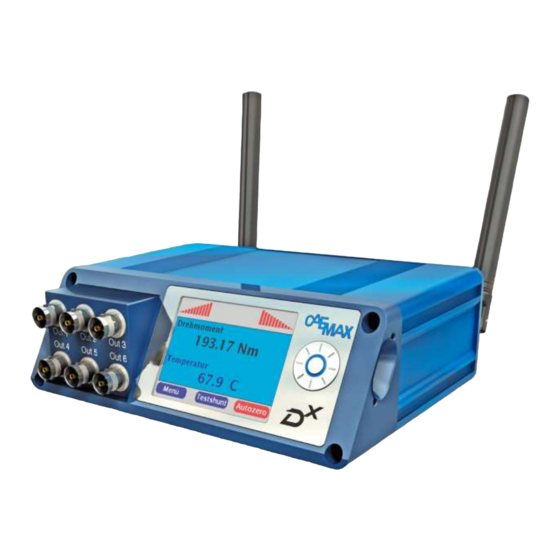
Page 15: Receiver Control Interface (Rci)
Telemetry System Manual Vers. 2.7 Receiver Control Interface (RCI) Figure 4: RCI front 2.3.1 Technical data Display: 2,83 inches IPS-display (In-Plane Switching) Resolution: 320 x 240 px Contrast: 10000:1 (TFT max. 400:1) Perspective: ±85° no preferred view angle (TFT approx. ±70°) Input interface: Rotary multi-selector with five keys Analog outputs:... -
Page 16: Connections
Telemetry System Manual Vers. 2.7 Synchronization: synchronized sampling and adjusted transmission frequencies of up to four D -SCT units, resulting in a synchronous data stream 9 – 36 volts DC Voltage supply: Input power < 5W (without inductive energy supply of the transmitters) Temperature range: -20°C - +65°C Dimensions:... - Page 17 Telemetry System Manual Vers. 2.7 2.3.2.1 Pin Assignment of D-Sub CAN Connector (9 pol) Figure 6: pin assignment of D-Sub CAN connector CiA name function not used CAN_L CAN_L, dominant low CAN_GND not used not used not used CAN_H CAN_H, dominant high not used not used...
-
Page 18: Quickstart
Telemetry System Manual Vers. 2.7 Quickstart Connect the D Connect the D RCI to a power source. Therefore, use the DC-Inputs (9-36V DC) or connect the included power cable to the mains voltage. To configure the D via PC, connect the PC and D with the included Ethernet cable. - Page 19 Telemetry System Manual Vers. 2.7 Figure 7: Network and Sharing Center To do this with Windows 7, open the Network and Sharing Center and click on LAN- Connection. In the LAN connection dialog, select Properties (Administrator privileges required!). Figure 8: LAN connection status Select Internet protocol Version 4 (TCP/IPv4) and click on Properties.
- Page 20 Telemetry System Manual Vers. 2.7 Figure 9: LAN connection properties Now select Use the following IP address, type in the desired IP address and confirm with OK. Figure 10: IP address If you don’t succeed in connecting to the D , please check your firewall settings.
- Page 21 Telemetry System Manual Vers. 2.7 Now open any web browser and type in the D network address (factory settings: 192.168.0.212). Figure 11: D menu You are now able to conveniently configure the D using your PC. Please note: The following steps (3.5 to 3.10) can be done either with the RCI scroll wheel or with your web browser.
-
Page 22: Add A New Sct
Telemetry System Manual Vers. 2.7 Add a New SCT 3.5.1 Create a New Device Switch on the SCT to be added to the RCI. All other SCTs must be switched off. Select Devices →New Device in the D menu. You have now created a new object Device X. Figure 12: Add a new SCT Please note: For more than one SCT to be added, create multiple new devices by selecting Devices →New Device multiple times. - Page 23 Telemetry System Manual Vers. 2.7 Figure 13: SCT setup In case the search has been successful, confirm the Device found! message with OK. Figure 14: Message ‘Device found!’ Now assign a Logical Number from 1-4 to the device, with each SCT being assigned a different number.
- Page 24 Telemetry System Manual Vers. 2.7 When operating only one SCT, assign it to Logical Number 1. The SCT may now use the whole transmission window (sections 1-4). When operating two SCTs, assign the first SCT to Logical Number 1, the second to Logical Number 3.
-
Page 25: Channel Configuration
Telemetry System Manual Vers. 2.7 Channel Configuration After you have added one or more SCTs to your telemetry system, the corresponding channels have to be created and programmed. 3.6.1 Generate a New Channel Connect the sensors to the D (see connecting diagram in section 2.2). Open Channels →... -
Page 26: Programming Of Channels
Telemetry System Manual Vers. 2.7 3.6.2 Programming of Channels After you have added one or more SCTs to your telemetry system, you proceed with programming at least one corresponding channel. To create a new channel, follow the instructions in section 3.6.1. Select the menu item Channels →... -
Page 27: Define A Sample Rate
Telemetry System Manual Vers. 2.7 3.6.3 Define a Sample Rate Each channel of one D system is assigned the same sample rate (except additional channels Reference Temp. and Supply Voltage). If you intend to change the sample rate of the D telemetry system, each SCT has to be reprogrammed individually. - Page 28 Telemetry System Manual Vers. 2.7 Number of SCTs max. n. of channels/SCT max. sample rate [Hz] 4600 2200 1400 1000 3600 1800 1200 3 or 4 1000 For example: when configuring 2 SCTs and the first SCT has 3 channels in use while the second only has 1.
- Page 29 Telemetry System Manual Vers. 2.7 Figure 19: Programming of sample rate Please note: Make sure the SCT is switched on (i.e. supplied with power) and radio transmission from RCI to SCT is undisturbed. Otherwise, the SCT can’t be programmed successfully. Confirm the message Program done! with OK.
-
Page 30: Configure Full Bridges / Half Bridges
Telemetry System Manual Vers. 2.7 3.6.4 Configure Full Bridges / Half Bridges Make sure the desired channel has been assigned the correct signal mode (see section 3.6.1). Open the desired channel by selecting Channels→Channel X. 3.6.4.1 Calibration In the Calibration section, enter a two-point calibration line in the fields Sample 1 and Sample 2. - Page 31 Telemetry System Manual Vers. 2.7 Figure 20: Strain gauge channel configuration...
-
Page 32: Configure Thermocouples (Differential Or Single Ended)
Telemetry System Manual Vers. 2.7 3.6.5 Configure Thermocouples (differential or single ended) Open the desired channel by selecting Channels → Channel X. 3.6.5.1 Calibration In the Calibration section, enter a two-point calibration line in the Sample 1 and Sample 2 fields. Define physical unit of output in the Units field. 3.6.5.2 Measurement Range Enter upper and lower bound of desired measurement range in the fields Range min: and Range max. -
Page 33: Configure High Level Voltage Inputs
Telemetry System Manual Vers. 2.7 3.6.6 Configure High Level Voltage Inputs Open the desired channel by selecting Channels → Channel X. 3.6.6.1 Calibration In the Calibration section, enter a two-point calibration line in the Sample 1 and Sample 2 fields. Define physical unit of output in the field Units. 3.6.6.2 Autozero Check the Autozero box if you do not want to adjust selected channel. -
Page 34: Configure Can Output
Telemetry System Manual Vers. 2.7 Configure CAN Output For each measurement timepoint, one or several CAN messages are transmitted, with each message containing up to four 16-bit measurement values. 3.7.1 Create/Delete CAN Message Select CAN-Setup → New Msg. in the menu. Select the active checkbox for this message to be transmitted in measuring mode. -
Page 35: Edit/Save Can Preferences
Telemetry System Manual Vers. 2.7 3.7.2 Edit/Save CAN Preferences 3.7.2.1 CAN-Bus Preferences Select CAN-Setup → General. In the Bitrate field, select bit rate of CAN bus (standard: 500 kBaud). Check the Ignore Acknowledge box to deactivate the CAN acknowledge function. If desired, type in a data compression factor in the field Send Rate: Sample Rate. - Page 36 Telemetry System Manual Vers. 2.7 3.7.2.3 Download .dbc File To download the .dbc file via Ethernet, select the menu item Download. Please note: This menu item is only displayed in your browser, not in the RCI. Select the .dbc file from the file list (default name: DX_CAN.dbc). Figure 25: Download .dbc file If there is no network connection established, remove the SD card of the D and insert it to...
-
Page 37: Configure Analog Output
Telemetry System Manual Vers. 2.7 Configure Analog Output Any measurement data channel of the D can be assigned to one of the 6 analog outputs. Select Output → Output X. Figure 26: Analog output configuration With Source, select the data channel to be displayed. Check the min/max = -10 V/+10 V box to set the upper/lower bounds of the measurement range (see 3.6.4.3) to -10 V/+10 Volts. -
Page 38: Save And Export Settings
Telemetry System Manual Vers. 2.7 Save and Export Settings The current configuration can be saved as a .dxp file. When loading the file, the configuration you have saved is restored. When booting the D , the DEFAULT.dxp configuration file is automatically loaded. If you save a configuration with DEFAULT.dxp as file name, it is immediately loaded when restarting the D 3.9.1 Save Configuration (create .dxp File) -
Page 39: Download .Dxp File
Telemetry System Manual Vers. 2.7 3.9.3 Download .DXP File To download the .dxp file via Ethernet, select the menu item Download in your browser. Please note: This menu item is only displayed in your browser and not in the RCI. Click on the file to be downloaded from the file list to import it. -
Page 40: Configure Online Display
Telemetry System Manual Vers. 2.7 3.10.2 Configure Online Display In measurement mode, the current measurement values are displayed on the screen. For this purpose, up to six display windows can be configured. Select the sub-item Display X from the Measure item. Select which channels you want to be displayed, from the dropdown menu. -
Page 41: Start And Stop Measurement
Telemetry System Manual Vers. 2.7 3.10.3 Start and Stop Measurement Select the sub-item Start in the menu item Measure. The D now switches to measurement mode. 3.10.3.1 Switch between Online Displays In your web browser, you may click on Page to switch between the six online displays. On the RCI, press the ‘up’... -
Page 42: Start Measurement Automatically (Auto Measure Start)
Telemetry System Manual Vers. 2.7 3.10.4 Start Measurement Automatically (Auto Measure Start) With these functions, the D automatically switches to measurement mode after booting. It is not necessary to start the measurement manually with Measure → Start. Select Options. Activate the Auto Measure Start checkbox. When configuring with a web browser, confirm your input with the Set button to resume it to the D Figure 30: D... -
Page 43: X Configuration Menu
Telemetry System Manual Vers. 2.7 Configuration Menu In this section, all functions of the D configuration menu are described in detail. Menu tree... - Page 44 Telemetry System Manual Vers. 2.7 Menu tree (continued)
-
Page 45: Settings
Telemetry System Manual Vers. 2.7 Settings 4.2.1 Menu: Device Base RCI Version: Information about the RCI version Radio frequency: You can set the required radio frequency through a drop-down menu. If you use several RCIs within a transmission area, they must be programmed with different frequencies. -
Page 46: Menu: Device Device1
Telemetry System Manual Vers. 2.7 4.2.2 Menu: Device Device1 Serial number: This number is used for addressing the SCT. Only this device is addressed when programming. Search: This function is used to search for the respective frequency according to the SCT. The “serial number” and the "logical number" are determined and entered into the field. -
Page 47: Menu: Device New Device
Telemetry System Manual Vers. 2.7 The settings (“radio frequency” and “logical number”) are transmitted Program: to the SCT with the serial number registered under “serial number”. Then a reset of the transmitter module is required. To do this, please disconnect the SCT power supply for at least 5 seconds. IMPORTANT: Make sure that the SCT is sufficiently supplied while programming and that no other SCT operates with the same frequency. -
Page 48: Menu: Channels Modes
Telemetry System Manual Vers. 2.7 4.2.4 Menu: Channels Modes Channel 1: Select the measuring mode for each respective channel. The following settings are available: Full bridge (strain gauges) Half bridge (strain gauges) with integrated bridge completion DC differential DC single ended Thermo differential Thermo single ended When a channel is used as a full bridge or in differential mode, the... -
Page 49: Menu: Channels Channel X
Telemetry System Manual Vers. 2.7 4.2.5 Menu: Channels Channel x Name: Enter a channel name with a maximum of 16 characters Units phys.: Enter the desired measuring unit Sample 1, Two-point calibration line for conversion of electrical signal (e.g. mV/V with bridges) to physical magnitude. -
Page 50: Menu: Outputs Output X
Telemetry System Manual Vers. 2.7 4.2.6 Menu: Outputs Output x Source: Choose the channel to be output. min/max: If this box is ticked the detected maximum signal range of this channel is converted into an analog signal. The output range is +/-10 Volt. -
Page 51: Menu: Can-Setup General
Telemetry System Manual Vers. 2.7 4.2.7 Menu: CAN-Setup General Bitrate: Select the transmission rate for the CAN-Bus. Extended Identifier: When ticked a 29-bit extended identifier is used, otherwise an 11-bit identifer is used. The RCI transmits data without the sender’s acknowledgement Ignore acknowledge: of receipt. -
Page 52: Menu: Can Setup Rem. Ctrl
Telemetry System Manual Vers. 2.7 4.2.8 Menu: CAN Setup Rem. Ctrl This function allows other devices to remotely activate “Autozero” or “Shunt test” on your system. Enter the desired CAN-Id for the "Autozero Message" in decimal or hexadecimal. (Autozero Message) Enter the desired CAN-Id for the "Shunt Message"... -
Page 53: Menu: Can-Setup Message X
Telemetry System Manual Vers. 2.7 4.2.9 Menu: CAN-Setup Message x Enter the desired CAN-ID of the message in decimal or hexadecimal. hex: Switch the CAN-Id between decimal and hexadecimal. active: Activate the message. The message will be sent via the CAN only if this box has been ticked. -
Page 54: Menu: Ethernet
Telemetry System Manual Vers. 2.7 4.2.11 Menu: Ethernet Ethernet-connection is set to “active” activate: IMPORTANT: As soon as the Ethernet-connection is set to “active” on the RCI, anyone having access to the network can configure the RCI. IP-Address: Set the IP address. The computer must be in the same segment. In this case (see figure above): 192.168.000.xxx. -
Page 55: Menu: Measure Start
Telemetry System Manual Vers. 2.7 4.2.13 Menu: Measure Start Indicates which display you are using. You can switch between displays by pressing up and down on the scrollwheel. dbm display: An indicator shows the signal strength as decimal or bar graph. Display type can be chosen in “Options ... -
Page 56: Menu: Options
Telemetry System Manual Vers. 2.7 4.2.14 Menu: Options Screen Saver Timeout: Time in seconds after which the screen saver is switched Date: Enter date in mm/dd/yyyy format. Time: Enter time in hh:mm:ss format Auto Measure Start: When ticked, the D RCI automatically switches to measurement mode after booting. -
Page 57: Menu: Load/Save
Telemetry System Manual Vers. 2.7 4.2.15 Menu: Load/Save File Name: Select the file name to be loaded or saved. The parameter file “DEFAULT.dxp” is loaded automatically when the system is booting. You can select existing filenames or enter a new file name. -
Page 58: Energy Supply Of Scts
Telemetry System Manual Vers. 2.7 Energy Supply of SCTs As telemetry transmitters are often placed on rotating devices, energy supply of transmitters is a challenging task. With the D telemetry system, there are several possibilities to solve this problem: supply by battery/rechargeable battery ... -
Page 59: Battery Supply
Telemetry System Manual Vers. 2.7 Battery Supply can be supplied with commercial 9 V batteries. Operating time is 3-6 hrs – dependent The D on sensors connected. Connect the positive pole of the battery to DC Power Plus, the negative to DC Power Ground (see section 2.2). -
Page 60: Technical Data
Telemetry System Manual Vers. 2.7 5.4.2 Technical Data Dimensions ca. 84x54x37mm w/o copper wire Diameter of copper wire ca. 8mm Weight ca. 324 g w/o copper wire -10°C … +85°C Temperature range 0 … 70 mm Transmission distance 30 … 1000 mm Diameter of primary coil Ratio secondary/primary coil >... - Page 61 Telemetry System Manual Vers. 2.7 Shape the copper band/copper tube to a ring as shown in Figure 32 and shorten it to the appropriate length. After a check-up of length and shape, drill a hole at each end of the copper band to fix it with 2 M5x6 screws to the stator housing (refer to Figure 33).
- Page 62 Telemetry System Manual Vers. 2.7 Figure 33: copper tube with holes Please note: The lower the distance between the primary coil and the secondary coil, the better the efficiency of the energy transfer. However, when installing take into account the height of the secondary coil and insulation layer, as well as any possible movements and unbalances to the shaft.
- Page 63 Telemetry System Manual Vers. 2.7 Figure 34: tightening of the stator ring Plug in the power cable of the ring stator and connect it to a 9 ...36 V DC power source. Please note: The DC connector of the D RCI is not designed to supply a ring stator or stator head while the RCI AC power supply is connected! ...
- Page 64 Telemetry System Manual Vers. 2.7 Figure 35: Adjusting the stator power via potentiometer screw For more detailed troubleshooting instructions, please refer to section 10.1.
-
Page 65: Stator Head
Telemetry System Manual Vers. 2.7 Stator Head The CAEMAX stator head provides noncontact energy supply of D transmitters (SCTs) by inductive coupling: An alternating magnetic field from the stator head induces voltage in the secondary coil on the device. This induced voltage is used for supply of the D transmitter unit (SCT). - Page 66 Telemetry System Manual Vers. 2.7 Please note: The operating point, i.e. the optimum frequency of the alternating electrical field, is automatically set and readjusted by the stator electronics. The operating point of the system is dependent on a variety of factors. If the stator is put into operation for the first time, the determination of the optimum frequency may take several minutes.
-
Page 67: Installation
Telemetry System Manual Vers. 2.7 Installation General Information The transducer (sensor), the DX -SCT and the transformer winding should be mounted close to each other. In order to obtain accurate measurement results, the connection wires between sensor and SCT have to be twisted in pairs, the signal lines In+ twisted with In- and the sensor supply cables +5 V twisted with GND. -
Page 68: Installation Of The Sct On A Rotating Device
Telemetry System Manual Vers. 2.7 Installation of the SCT on a Rotating Device After the sensors have been connected to the SCT, it can be fastened to the rotating device. Figure 36: Shaft with SCT When attaching the SCT, make sure that it is supported on the shaft. If necessary, a suitable substructure must be constructed. -
Page 69: Installation Of Secondary Coil For Inductive Power Supply
Telemetry System Manual Vers. 2.7 Installation of Secondary Coil for Inductive Power Supply Measurements on rotating shafts are a standard application of the D telemetry system. All steps for attaching a secondary winding on the shaft are shown below. The required materials can be ordered at CAEMAX (D mounting kit). -
Page 70: Step By Step Instructions
Telemetry System Manual Vers. 2.7 6.5.2 Step by Step Instructions 1. Wrap the shaft with insulating tape. Figure 38: insulation of the shaft The insulated surface has to cover a larger area than the Mu-metal to be applied subsequently in order to prevent short-circuit between the Mu-metal and the shaft. 2. - Page 71 Telemetry System Manual Vers. 2.7 5. Insulate the second mu-metal layer completely (see step 1). 6. Apply a first layer of heat resistant tape. 7. Apply the secondary copper winding centrally to the insulated mu-metal (see figure 40). Please note: Leave a gap of approx. 1mm between both ends of the copper band. If the ends of the secondary coil (copper band) contact, the device will not be supplied with energy.
- Page 72 Telemetry System Manual Vers. 2.7 The strands should be soldered as flat as possible to the copper band. Sensor cables and connection cables should not cross. Wrap the secondary coil with 3 layers of heat- resistant adhesive tape to prevent overheating. For measurements on high speed or high temperature shafts, CAEMAX offers special solutions (half shells, special casings, etc.) For further questions and instructions concerning your individual situation, please contact...
-
Page 73: Accessories
Telemetry System Manual Vers. 2.7 Accessories Casings for D Transmitter Units We offer a variety of different types of casings for SCT mounting and protection, which can be customized in size and shape for your application. 7.1.1 SCT casing with Breakout Cable Figure 43: SCT casing with breakout cable Technical data: dimensions 72mm x 55mm x 10mm... -
Page 74: D X Antennas
Telemetry System Manual Vers. 2.7 cable 8 x 24AWG (sensors) shielding connected to EX- black brown orange yellow green blue purple Antennas For trouble-free signal transmission in different applications, select from a variety of antenna types. 7.2.1 Planar Antenna Cable length approx. 5 m (optional 7 … 10m), SMA connector Universal mounting possibilities Dimensions: 72mm x 55mm x 10mm POM material... -
Page 75: Side Mirror Antenna
Telemetry System Manual Vers. 2.7 7.2.2 Side Mirror Antenna For driving tests on public roads, the measurement system should be constructed as unobtrusively as possible. With the supplied rubber strap holder, the antenna can be attached quickly and easily to the side mirrors of the vehicle. Figure 45: D side mirror antenna Satellites... -
Page 76: X Custom Systems
Telemetry System Manual Vers. 2.7 Custom Systems RPM measurement option 8.1.1 System Overview The system consists of a modified receiver unit (RCI) and one or more transmitter units (see section 2.2). For RPM measurement, the included incremental angle sensor is used. With the RPM measurement option, the menu navigation differs in some points from the standard menu described in section 4.1. -
Page 77: Incremental Angle Sensor
Telemetry System Manual Vers. 2.7 8.1.3 Incremental Angle Sensor Figure 48: Incremental angle sensor Technical Specification Diameter: 100 mm Number of increments: 8000 max. measurable rotational ± 5999 rpm speed: System accuracy: ± 0.1° -10°C … +70°C Working temperature: Vibration resistance: 10 g/50 Hz Supply voltage stator head: 24V/DC, supply via RCI... -
Page 78: Operating Instructions
Telemetry System Manual Vers. 2.7 8.1.4 Operating Instructions Please note: Due to system modifications, only one satellite receiver can be used in your telemetry system, with the other D-SUB 15 connector being used to connect the incremental angle sensor. 8.1.5 Instructions for Commissioning and Maintenance Please note: When installing the stator head, take care to be compliant with the specified clearance dimensions (see figure below). -
Page 79: Settings
Telemetry System Manual Vers. 2.7 Settings The menu of the D special system for measuring rotational speed is identical to the D standard menu (see section 4.1) in large parts. All the different menu items are described below. 8.2.1 Menu: Channels → Local/RCI → Selection Angle: Angle of rotation (fixed channel assignment) Rot. -
Page 80: Menu: Channels → Local/Rci → Dx_Angle
Telemetry System Manual Vers. 2.7 8.2.2 Menu: Channels → Local/RCI → DX_Angle Name: Channel name Sample 1 Two-point calibration of channel Sample 2: Please note: no input required here due to factory calibration Range min Minimum output value (fix -1473.560°) Range max: Maximum output value (fix +1473.560°)) Sample Rate:... -
Page 81: Menu: Channels → Local/Rci → Rot. Speed
Telemetry System Manual Vers. 2.7 8.2.3 Menu: Channels → Local/RCI → Rot. Speed Name: Channel name Sample 1 Two-point calibration of channel Sample 2: Please note: no input required here due to factory calibration Range min minimal value ( -5999.97 rpm fixed) Range max: maximal value ( 5999.97 rpm fixed) Sample Rate:... -
Page 82: Menu: Channels → Local/Rci → Rot.power
Telemetry System Manual Vers. 2.7 8.2.4 Menu: Channels → Local/RCI → Rot.Power Name: Channel name Sample 1 Two-point calibration of output. Sample 2: Please note: no input required here due to factory calibration Range min Minimum measurement value (calculated from channels Rot.Speed and Channel_1) Range max: Maximum measurement value (calculated from channels Rot.Speed... -
Page 83: Maintenance And Storage
Telemetry System Manual Vers. 2.7 Maintenance and Storage Cleaning and Maintenance Due to its construction, the telemetry system is protected against contamination of its electronic parts. Contaminations of the case can be removed with non-agressive agents like isopropyl alcohol when the device is switched off. Due to constructional design of D transmitter and receiver, there is no maintenance required, if cables are protected from mechanical stress. -
Page 84: Questions & Answers
Telemetry System Manual Vers. 2.7 10 Questions & Answers 10.1 Inductive Power Supply: Troubleshooting... - Page 85 Telemetry System Manual Vers. 2.7...
- Page 86 Telemetry System Manual Vers. 2.7...
-
Page 87: Integration Of Scts
Telemetry System Manual Vers. 2.7 10.2 Integration of SCTs If problems with your telemetry systems occur, it can be necessary to reintegrate the SCTs. In that case, please regard the following instructions. 1. Turn the D RCI on. 2. With Devices → Device X, delete all registered devices with the Delete button. 3. -
Page 88: Unstable Signal, When Connecting More Than One Sct
Telemetry System Manual Vers. 2.7 15. Switch on SCT 3 and proceed with the transmitter connection as described in 3-8. However, select a different transmission frequency (e.g., = 870 MHz). freq2 16. Switch on SCT4 and proceed as described in section 10. Select the same transmission frequency as for SCT3 (e.g., = 870 MHz). -
Page 89: D Xrci Firmware Update
Telemetry System Manual Vers. 2.7 10.5 D RCI Firmware Update 10.5.1 Checking firmware status You can see the firmware status of your D telemetry system in the Options menu under Firmware Version. 10.5.2 Download new firmware The latest firmware version can be found in the download area of the CAEMAX homepage http://www.caemax.de/support/downloads/ Please note that you must register to download software on our homepage. - Page 90 Telemetry System Manual Vers. 2.7 Figure 50: Firmware upload In the Select File to Upload section, select the FIRMWARE.hex file from the Browse button and click Upload. The file is now written to the root directory of the SD card. Now switch the D off and on again (see section 3.3).
-
Page 91: Eg Declaration Of Conformity (After En Iso/Iec 17050-1:2010)
Telemetry System Manual Vers. 2.7 11 EG Declaration of Conformity (after EN ISO/IEC 17050-1:2010) The manufacturer CAEMAX Technologie GmbH Bunzlauer Platz 1 D-80992 München Declares that the following product: Product name : telemetry Type -RCI / D -SCT Serial number : DX-RCI-xxxxx / DX-SCT-xx-xxx is in conformity with the following provisions: ... -
Page 92: Formulas
Telemetry System Manual Vers. 2.7 12 Formulas 12.1 Sensitivity of torsion measuring points The following formulas are valid for a steel shaft, a full bridge and a k factor of 2.0 for the strain gauge. = Sensitivity in mV/V = Sensitivity in mV/V STEEL = Maximum torque in Nm TMAX...
Need help?
Do you have a question about the CAEMAX DX and is the answer not in the manual?
Questions and answers