Vetus RimDrive RD160 Installation Manual
Hide thumbs
Also See for RimDrive RD160:
- Installation instructions manual (158 pages) ,
- Installation manual (152 pages) ,
- Operation manual (48 pages)
Table of Contents

Related Manuals for Vetus RimDrive RD160


Summary of Contents for Vetus RimDrive RD160
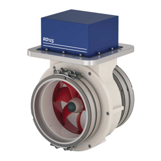
- Page 1 NEDERLANDS ENGLISH Installatieinstructies Installation manual Installation manual RimDrive RD125 / RD160 125 kgf / 160 kgf - ø 250 mm Copyright © 2016 Vetus b.v. Schiedam Holland 020574.01...
-
Page 2: Table Of Contents
Battery capacity ......34 Raadpleeg de eigenaarshandleiding voor Bediening, Onderhoud, Consult the owner’s manual for Operation, Maintenance, Trouble Storingen en Technische gegevens.’ shooting and Technical data. Preliminary vetus® Installation instructions thruster RIM DRIVE 250 mm 020574.01... -
Page 3: Veiligheid
NEDERLANDS Veiligheid Inleiding Deze handleiding geeft richtlijnen voor de inbouw van de Vetus Waarschuwingsaanduidingen boegschroef en/of hekschroef type ‘RimDrive’ . In deze handleiding worden in verband met veiligheid de volgende waarschuwingsaanduidingen gebruikt: Bij toepassing als boegschroef wordt de ‘RimDrive’ altijd in een tun- nelbuis ingebouwd. -
Page 4: Opstelling Van De Tunnelbuis
Indien een tunnelbuis voor een hekschroef wordt toegepast dient deze tunnelbuis zover mogelijk naar achteren in het schip te wor- den geïnstalleerd. Preliminary vetus® Installation instructions thruster RIM DRIVE 250 mm 020574.01... -
Page 5: Opstelling Boegschroef In Tunnelbuis
De ‘RimDrive’ kan in verschillende standen worden ingebouwd, van horizontaal tot ver- tikaal naar boven. 180º De aansluitkast dient steeds boven het maxi- male niveau van het bilge-water te worden opgesteld. Max. niveau bilge-water Preliminary vetus® Installation instructions thruster RIM DRIVE 250 mm 020574.01... -
Page 6: Overgang Van Tunnelbuis Naar Scheepsromp
L = 1 x D ... 3 x D vorm van de boeggolf. α α : min. 0º max. 15º Boegschroef ‘RD ..’ [mm] [mm] RD125 RD160 250 ... 750 Preliminary vetus® Installation instructions thruster RIM DRIVE 250 mm 020574.01... -
Page 7: Spijlen In De Tunnelbuis-Openingen
De spijlen moeten een zekere overlapping te hebben. 250 mm De spijlen moeten zodanig zijn opgesteld dat ze loodrecht staan op de te verwachten golfvorm. α α : min. 0º max. 15º Preliminary vetus® Installation instructions thruster RIM DRIVE 250 mm 020574.01... -
Page 8: Aanbrengen Van De Tunnelbuis
én op de juiste afstand van elkaar. Gebruik alleen de klembanden om de af- standshouders vast te zetten! et op Gebruik de rubber moffen en de kunststof schaaldelen niet! Preliminary vetus® Installation instructions thruster RIM DRIVE 250 mm 020574.01... -
Page 9: Een (1) Enkele Tunnelbuis
‘epoxyverf’ of 2-componenten polyu- rethaanverf. Controleer of de afstand tussen de tunnel- • Breng hierna eventueel een anti-fou- 248 - 250 mm buiseinden correct is: 248 - 250 mm. ling aan. Preliminary vetus® Installation instructions thruster RIM DRIVE 250 mm 020574.01... - Page 10 In verband met de toleraties op de tunnel- buizen kan een verschil in diameter tussen de tunnelbuis en de Rimdrive voorkomen. Gebruik de smalle rubbermoffen om dit ver- schil op te vangen. Preliminary vetus® Installation instructions thruster RIM DRIVE 250 mm 020574.01...
- Page 11 Breng een deugdelijke ondersteuning onder ≥ 250 mm de RimDrive aan in bij: - Een tunnelbuislengte van meer dan 250 mm van RimDrive tot aan de romp. - Snelvarende c.q. planerende schepen. Preliminary vetus® Installation instructions thruster RIM DRIVE 250 mm 020574.01...
-
Page 12: Bescherming Van De Boegschroef Tegen Corrosie
Min. 250 mm optredende kracht van het water tijdens de normale vaart op te kunnen nemen. Laat de ‘RimDrive’ bij voorkeur niet onder het vlak uitsteken. Preliminary vetus® Installation instructions thruster RIM DRIVE 250 mm 020574.01... -
Page 13: Elektrische Installatie
: 55 Ah, 70 Ah, 90 Ah, 108 Ah, De Vetus gesloten onderhoudsvrije accu’s type ‘SMF’ en ‘AGM’ zijn hiervoor bij uitstek geschikt. 120 Ah, 143 Ah, 165 Ah, 200 Ah en 225 Ah. -
Page 14: Laadvoorziening
In de ‘plus-kabel’ moet naast de hoofdscha- Voor alle zekeringen kunnen wij ook een kelaar en het hoofdrelais ook een zekering zekeringhouder leveren, Vetus art. code: worden opgenomen van 200 A . Vetus art. ZEHC100 code: ZE200. De zekering beschermt de boegschroef te- gen overbelasting en tevens het boordnet tegen kortsluiting. -
Page 15: Hoofdstroomkabels (Accukabels)
Voordat het deksel weer terug wordt geplaatst moet het zakje silica- gel uit de verpakking worden genomen en in de aansluitkast worden gelegd. Aantasting van de regelaar door condens wordt hiermee voorkomen. Preliminary vetus® Installation instructions thruster RIM DRIVE 250 mm 020574.01... -
Page 16: Boegschroefbedieningen
• Druk op een van de panelen de HOUD-schakelaar in, met de joy- stick in de middenstand, en houdt deze gedurende 5 seconden ingedrukt tot een pieptoon klinkt. Preliminary vetus® Installation instructions thruster RIM DRIVE 250 mm 020574.01... -
Page 17: Safety
ENGLISH Safety Introduction These manual give guidelines for fitting the Vetus bow and/or stern Warning indications thruster model ‘RimDrive’ . The following warning indications are used in this manual in the con- text of safety: When used as a bow thruster, the ‘RimDrive’ is always mounted in a tunnel. -
Page 18: Positioning Of Thrust Tunnel
If a tunnel for a stern thruster is used then po- sition this thrust tunnel as close as possible near the stern of the boat. Preliminary vetus® Installation instructions thruster RIM DRIVE 250 mm 020574.01... -
Page 19: Positioning Of The Bow Thruster In The Thrust-Tunnel
The ‘RimDrive’ can be installed in various po- sitions from horizontal to vertically upwards. 180º The connection box must always be posi- tioned above the maximum level of the bilge water. Max. bilge water level Preliminary vetus® Installation instructions thruster RIM DRIVE 250 mm 020574.01... -
Page 20: Connection Of Thrust Tunnel To Ship's Hull
α α : min. 0º max. 15º Thruster ‘RD ..’ [mm] (inches) [mm] (inches) RD125 RD160 ”) 250 ... 750 (10 ... 30”) Preliminary vetus® Installation instructions thruster RIM DRIVE 250 mm 020574.01... -
Page 21: Grid Bars In The Tunnel Openings
The bars must overlap a certain amount. 250 mm (10”) The bars must be installed so that they stand perpendicular to the expected wave form. α α : min. 0º max. 15º Preliminary vetus® Installation instructions thruster RIM DRIVE 250 mm 020574.01... -
Page 22: Installation Of The Thrust Tunnel
Use only the clamping straps to secure the strips! Do not use the rubber sleeves and the plas- tic slabs! Preliminary vetus® Installation instructions thruster RIM DRIVE 250 mm 020574.01... -
Page 23: Tunnel In One (1) Part
‘epoxy paint’ or 2-component polyure- thane paint. • Then apply anti-fouling treatment if Check that the distance between the tunnel 248 - 250 mm required. ends is correct: 248-250 mm. ” - 9 ”) Preliminary vetus® Installation instructions thruster RIM DRIVE 250 mm 020574.01... - Page 24 A difference in diameter between the tunnel tube and the Rimdrive may occur due to tol- erances on the tunnel tubes. Use the narrow rubber sleeves to overcome this difference. Preliminary vetus® Installation instructions thruster RIM DRIVE 250 mm 020574.01...
- Page 25 Apply a proper support under the RimDrive ≥ 250 mm (10”) in case of: - A tunnel tube length of more than 250 mm from RimDrive to hull. - High speed or planing vessels. Preliminary vetus® Installation instructions thruster RIM DRIVE 250 mm 020574.01...
-
Page 26: Protection Of The Bow Thruster Against Corrosion
Min. 250 mm tions. It is preferred to not have the ‘RimDrive’ (10”) protrude below the bilge. Preliminary vetus® Installation instructions thruster RIM DRIVE 250 mm 020574.01... -
Page 27: Electrical Installation
We recommend Vetus maintenance-free batteries, which are avail- The Vetus ‘SMF’ and ‘AGM’ maintenance-free batteries are ideally suit- able in the following capacities: 55 Ah, 70 Ah, 90 Ah, 108 Ah, 120 Ah, ed to this application. -
Page 28: Charging Facility
The main switch must be fitted to the ‘posi- The BATSW250 is also available in a 2-pole tive cable’ . version, Vetus art. code BATSW250T. The Vetus battery switch type BATSW250 is a suitable switch. 10.4 Main relay, see diagram page 32 - 2 -... -
Page 29: Main Power Cables (Battery Cables)
Before the lid is put back the sachet of silica gel must be taken out of the package and placed inside the terminal box. Affect of the controller by condensation is so prevented. Preliminary vetus® Installation instructions thruster RIM DRIVE 250 mm 020574.01... -
Page 30: Bow Thruster Controls
• With the joystick in the centre position, press and hold the HOLD button on one of the panels for 5 seconds until you hear a peep sound. Preliminary vetus® Installation instructions thruster RIM DRIVE 250 mm 020574.01... -
Page 31: Hoofdafmetingen
76 (3“) 88 (3 “) 62 (2 “) Made in Holland Interface RimDrive Control For 48 V DC RimDrive RDIF Model No.: Serial No.: Reset Panel A Panel B Thruster Controller Preliminary vetus® Installation instructions thruster RIM DRIVE 250 mm 020574.01... -
Page 32: Elektrisch Schema
Main relay 3 Hoofdzekering Main fuse 4 Stuurstroomzekering Control current fuse 5 Steker Plug 6 Thruster Thruster 7 Interface Interface 8 Bedieningspaneel Control panel 9 Accu Battery 10 Laadaansluiting Charge connection Preliminary vetus® Installation instructions thruster RIM DRIVE 250 mm 020574.01... - Page 33 For 48 V DC RimDrive RDIF Model No.: RJ45P01Y Serial No.: RJ45P01Y Reset Panel A Panel B Thruster Controller RJ45P05Y RJ45P10Y 10 m Art. code RDICAB06 RDICAB10 10 m RDICAB15 15 m • aa Preliminary vetus® Installation instructions thruster RIM DRIVE 250 mm 020574.01...
-
Page 34: Accucapaciteit
BCI 4D - 1050 BCI 4D - 1050 BCI 4D - 1050 4 x BCI 31 - 750 8 x 165 Ah - 12 V 8 x BCI 4D - 1050 Preliminary vetus® Installation instructions thruster RIM DRIVE 250 mm 020574.01... -
Page 35: Declaration Of Conformity
EN 55011 EN 61000 2014/30/EU 93/68/EEC Schiedam, 16 03 2016 Ing. P.H. le Pair Vetus B.V. Fokkerstraat 571 3125 BD Schiedam The Netherlands Preliminary vetus® Installation instructions thruster RIM DRIVE 250 mm 020574.01... - Page 36 FOKKERSTRAAT 3125 SCHIEDAM HOLLAND TEL.: 4377700 TELEFAX: +31 10 4372673 - 4621286 - E-MAIL: sales@vetus.nl - INTERNET: http://www.vetus.com Printed in the Netherlands 020574.01 2016-06...
Need help?
Do you have a question about the RimDrive RD160 and is the answer not in the manual?
Questions and answers