Advertisement
Quick Links
Light My Bricks
Installation Instructions for Light My Bricks LED Lighting Kits
Sep 14 · 34 min read ·
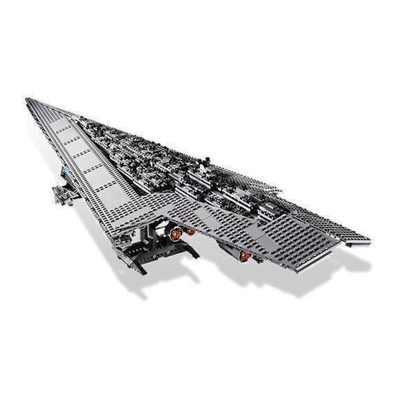
Light My Bricks: LEGO Super Star
Destroyer 10221 Lighting Kit
The following page is the instructions for the Light My Bricks LEGO Super
Star Destroyer (10221) LED light kit.
To ensure a trouble-free installation of your light kit, please read and
follow each step carefully.
Please note: This page lists instructions for the
LED light kit only. If you are wishing to purchase
the Light My Bricks LEGO Super Star Destroyer
(10221) LED light kit , please click here to view
the product page
Unlisted
. . .
Advertisement

Related Manuals for LIGHT MY BRICKS LEGO Super Star Destroyer 10221 Lighting Kit


Summary of Contents for LIGHT MY BRICKS LEGO Super Star Destroyer 10221 Lighting Kit
- Page 1 Light My Bricks: LEGO Super Star Destroyer 10221 Lighting Kit The following page is the instructions for the Light My Bricks LEGO Super Star Destroyer (10221) LED light kit. To ensure a trouble-free installation of your light kit, please read and follow each step carefully.
-
Page 2: Package Contents
Package Contents: 1x White Strip Light • 8x Blue Strip Lights • 13x White 30cm Bit Lights • 14x Blue 30cm Bit Lights • 4x Cool White 30cm Bit Lights • 1x 6-Port Expansion Board • 2x 8-Port Expansion Boards •... - Page 3 CAUTION: Forcing LEGO® to connect over a cable can result in damaging the cable and light. Connecting cable connectors to Expansion Boards Take extra care when inserting connectors to ports of Expansion Boards. Connectors can be inserted only one way. With the expansion board facing up, look for the soldered “=”...
- Page 4 Incorrectly inserting the connector can can result in bent pins inside the port or possible overheating of the expansion board when connected. Connecting cable connectors to Strip Lights Take extra care when inserting connectors to ports on the Strip Lights. Connectors can be inserted only one way.
- Page 5 When installing Bit Lights under LEGO® pieces, ensure they are placed the correct way up (Yellow LED component exposed). You can either place them directly on top of LEGO® studs or in between..OK, Let’s Begin! . . . 1.) Start by disconnecting the two long roof sections that run along each side of the Star Destroyer...
- Page 6 Turn the ship around so we can access the back, then disconnect the centre jet section followed by the two side jet sections.
- Page 7 2.) Take the centre jet section and follow the images below to disconnect sections so that we can disconnect the jets.
- Page 9 3.) Follow the below images to disassemble the jet section 4.) Take a the left jet and then turn it over so we can access the back. Take a White 30cm Bit Light and thread it down one of the bottom holes and then out to the right.
- Page 10 Thread the Bit Light all the way through and then bend it slightly toward the centre in between the four holes. Secure the Bit Light in place by reconnecting the trans orange piece over the top.
- Page 11 5.) Take the right jet and then repeat the same process used for the left jet to install another White 30cm Bit Light to it. 6.) Take the centre jet and install another White 30cm Bit Light the same way we did for the left and right jets.
- Page 12 Turn the jet over and reconnect the 2x3 plate we removed earlier underneath ensuring the cable is laid in between studs.
- Page 13 7.) Reconnect the three jets together then group the three cables and thread them inside the space behind before reconnecting to the main jet section.
- Page 14 Reconnect surrounding pieces which we removed back at step 2. 8.) Disconnect the left set of jets from the main section and then followthe images below to disassemble it.
- Page 15 Turn the below piece over to access the back then install another White 30cm Bit Light the same way we did for the previous jets.
- Page 16 Reconnect this piece back to the rest and then reconnect surrounding pieces.
- Page 17 9.) Take the following 2x2 round brick and turn it over to access thebase of it. Take another White 30cm Bit Light and thread it through the centre hole all the way through. Slightly bend the Bit Light so that it is directly facing upward before pushing it down and reconnecting the trans orange plate over the top.
- Page 18 Turn the piece over and reconnect the dark grey round plate ensuring the cable is laid in between the studs.
- Page 19 Reconnect this piece by pushing it back onto the technic bar. Do this very carefully to ensure the cable does not break. Reconnect surrounding pieces we removed earlier Turn this section over and then lay the cable underneath the 1x4 plate as per below then reconnect this section back to the main centre section.
- Page 20 10.) Disconnect the right set of jets and then install another 2x White 30cm Bit Lights to it the same way we did for the left set of jets (Step 8–9)
- Page 23 Reconnect the right jets back to the main centre jet section.
- Page 24 11.) We will now move onto installing lights to the left jet section. Take this section and disconnect and disassemble the jets as per below images.
- Page 25 Turn this section over and remove the 2x3 brick from underneath. 12.) Install a White 30cm Bit Light by threading it through the bottom hole of the main section and securing it by reconnecting the trans orange piece over the top as per below:...
- Page 26 Turn this section over and reconnect the 2x3 brick underneath ensuring the cable is placed in between studs...
- Page 27 13.) Install another 2x White 30cm Bit Lights to the remaining jets in this section following the same method used for the jets in step 9. Slightly bend the Bit Light so that it is directly facing upward before pushing it down and reconnecting the trans orange plate over the top. Important Note: Allow some excess cable inside the hole of the round brick for the technic bar to push through the back.
- Page 28 Turn the piece over and reconnect the dark grey round plate ensuring the cable is laid in between the studs.
- Page 29 Reconnect each jet section by pushing each one back onto the technic bar behind. Do this very carefully to ensure the cable does not break. 14.) Reconnect the jets back to the left section and then turn it overand lay the three cables underneath the 1x6 tile along the back. Ensure the cables are laid in between studs.
- Page 31 15.) Repeat previous steps 11–14 to install another 3x White 30cm Bit Lights to the jets on the right section.
- Page 34 16.) Reconnect the left and right jet sections and then pull out the three cables from each side at the front as per below...
- Page 35 Reconnect the main centre jet section and bring the cables out to the left side.
- Page 36 Take the seven cables from the centre jet section and connect them to an 8-Port Expansion Board. Take a 5cm Connecting Cable and connect one end to the remaining port on the expansion board and the other end to one of the OUT ports on the Multi E ects Board (side with 2 ports) Tuck the expansion board and seven cables neatly inside the left side of the ship as per below 17.) Remove the top section that covers the control room area then...
- Page 38 Bring the three cables from the left jet section together and pull them up along the back across the control room. Reconnect sections we removed earlier over the top.
- Page 39 Turn the ship over to the right side and do the same for the cables from the right jet section.
- Page 41 18.) Take another 8-Port Expansion Board and connect all six cables to it (three cables from each side jet section) Take a 15cm Connecting Cable and connect it to a spare port on the expansion board.
- Page 42 Turn the ship back around to the left side and then connect the other end of the 15cm connecting cable to the other OUT port on the Multi E ects Board. 19.) Take the AA Battery Pack and insert 3x AA batteries to it. Place the battery pack on top of the ship and connect the battery pack cable to the IN port on the multi e ects board.
- Page 43 Con gure your desired e ect as well as the speed of the e ect by icking the switch and turning the speed wheel. The e ect chosen in our product video was the ‘pulse’ e ect. To con gure this e ect, ick the switch to the far left and turn the speed wheel all the way to the left as shown below.
- Page 44 Remove the following sections along the left side again and neatly place all cables underneath before reconnecting the sections over the top.
- Page 45 20.) We will now install seven lights along each side of the ship. Starting toward the back, remove the following LEGO grill tile.
- Page 46 Take a Blue 30cm Bit Light and with the cable facing up, place it over the left stud as per below. Secure it in place by connecting a provided LEGO Trans Clear Plate 1x1 over the top.
- Page 47 Hide the cable by laying it underneath the following 2x4 tile ensuring the cable is laid in between studs. 21.) Install another Blue 30cm Bit Light to the next grill tile along the left side of the ship except this time, install the light to the stud on the left rather than in lieu of the grill plate.
- Page 48 Hide the cable underneath the following tile ensuring the cable is laid in between studs.
- Page 49 22.) Repeat previous step to install another 5x Blue 30cm Bit Lights to the left side of the remaining grill plates along the side. Secure them all in place using one of the 5x provided LEGO Trans Clear Plate 1x1 and hide the cables underneath the tiles above each light.
- Page 51 23.) Take the back three blue bit light cables as well as the other end ofthe 15cm connecting cable from the multi e ects board (Step 19) and connect them to the rst few ports on a 12-Port Expansion Board Take a 50cm Connecting Cable and connect it to the far left port on the 12-port expansion board.
- Page 52 24.) Take the remaining four blue bit light cables toward the top of the ship and connect them to the 12-Port Expansion Board near by.
- Page 53 Take the AA Battery pack and connect the battery pack cable to the 12port Expansion Board. Turn the battery pack ON to test all the blue lights are working OK. They should be illuminated along with the back jet lights however, they should be static (steady ON). 25.) Turn the ship over to the other side and then follow steps 20–22 to install another 7x Blue 30cm Bit Lights along the right side of the ship.
- Page 55 26.) Remove the following sections on the right side of the ship.
- Page 56 Take the back three blue bit light cables and connect them to the 12Port Expansion Board near the control room area. Group the three cables together and secure them along the back side of the control room. Reconnect sections we removed earlier over the top.
- Page 57 27.) Take the four remaining blue bit light cables toward the top rightside of the ship and connect them to the next ports along on the 12port expansion board above.
- Page 58 Turn the Battery Pack ON to verify all lights along the two sides are working OK...
- Page 59 28.) Turn the ship back over to the left side and neaten up cables. Startby grouping together the four cables at the front of the ship (two from each side). Fold and twist them around each other several times so they all come together.
- Page 60 Take the next two cables along the each side and then fold and twist them together before tucking them into the spaces below.
- Page 62 29.) Tidy up excess cables inside the control room area by grouping them together, folding and twisting them around each other the same way we did for the cables toward the front of the ship.
- Page 63 30.) Take a White Strip Light and connect a 5cm Connecting Cable to one side. Connect the other end of the connecting cable to a spare port on the 12-port expansion board in the control room area. Using the strip light’s adhesive backing, stick the strip light down on the the oor of the control room toward the front area as per below...
- Page 64 31.) We will now install some lights to the top of the star destroyer.First disconnect the following two dark grey round plates from the top toward the back of the ship.
- Page 65 Disconnect the section underneath as per below...
- Page 66 32.) Take a Cool White 30cm Bit Light and with the cable facing toward the control room, place it over the left stud where we disconnected one of the dark grey round plates from. Secure it in place by connecting a provided LEGO Trans Clear Round Plate 1x1 over the top, then hide the cable underneath the LEGO grill tile as shown below.
- Page 67 33.) Install another Cool White 30cm Bit Light to the right stud where we removed the other dark grey round plate from. Secure it in place using another provided LEGO Trans Clear Round Plate 1x1 then hide the cable underneath the grill tile.
- Page 68 34.) Lay the two cables down in between studs before reconnecting thesection we removed earlier...
- Page 69 Bring both cables down the left side of the star destroyer then remove the following side sections again 35.) Connect the two cables to a 6-Port Expansion Board. Take another 15cm Connecting Cable and connect it to the far end port on the expansion board.
- Page 70 Connect the other end of the 15cm connecting cable to a spare port on the 12-Port Expansion Board in the control room area.
- Page 71 Lay all cables neatly along the back side of the control room (right side) and then reconnect sections we removed earlier over the top. Turn the battery pack ON to ensure all lights are working OK.
- Page 72 36.) We will now install lights to the back of the small star destroyer. Take this section and turn it over to the back. Flip it over to allow us to disconnect and disassemble the following pieces.
- Page 73 37.) Take a Cool White 30cm Bit Light and place it over the top of one of the round plates. Secure it in place by reconnecting a trans light blue plate over the top. Take another Cool White 30cm Bit Light and place it over the top of the tile with stud.
- Page 74 Install the remaining Cool White 30cm Bit Light to the other dark grey round plate and secure it in place by reconnecting the trans light blue plate over the top 38.) Reconnect the three pieces back to the dark grey 1x4 brickensuring all cables are facing down.
- Page 75 Reconnect the 1x4 brick to the small star destroyer, then reconnect the remaining piece ensuring the cables are laid in between studs. Group the three cables together close to the ship and then twist and wind them together so that they come together. Continue to twist/wind the cables around each other all the way to the top so that they all form one larger cable.
- Page 76 Thread the cables in between the two trans clear bars and then pull the cable up all the way through. Turn the ship back over and then reconnect it to the left side of the super star destroyer toward the middle.
- Page 77 39.) Bring the cables over toward the back and then connect all three to the 6-port Expansion Board from step 35. Turn the battery pack ON to verify all lights are working OK...
- Page 78 40.) Take the roof of the control room area we removed earlier and then push the AA battery pack into the space underneath ensuring the ON/OFF switch is accessible. Neaten up cables underneath before securely reconnecting the roof back on top of the control room. 41.) We will now install strip lights along each roof section of the ship.
- Page 79 Take 4x Blue Strip Lights and stick three of them to the base of 3x Provided LEGO plate 1x6 Take a 15cm Connecting Cable and connect it to one of the strip lights that are stuck to a LEGO plate. Take another 3x 15cm Connecting Cables and connect the remaining strip lights together ensuring the strip light that is not stuck to a LEGO plate is on the very end.
- Page 80 Using the adhesive backing on the end strip light, stick it down toward the right side of the roof section in the following position. Ensure the other components are on the left side.
- Page 81 Mount the next two strip lights using the LEGO plate it is stuck to underneath the roof section in the following positions. Mount the fourth strip light in the following position and then ensure all cables in between strip lights are tucked upward.
- Page 82 42.) We will now install Blue Strip Lights underneath the right roof section, the same way as we did for the left roof section. Take the right roof and then turn it over so that we can access underneath.
- Page 83 Follow the same method used in previous step to install another 4x Blue Strip Lights underneath the right roof. Take a 15cm Connecting Cable and connect it to one of the strip lights that are stuck to a LEGO plate. Take another 3x 15cm Connecting Cables and connect the remaining strip lights together ensuring the strip light that is not stuck to a LEGO plate is on the very end.
- Page 84 Stick / Mount the strip lights in the following positions...
- Page 86 43.) Take the entire right roof and turn it over. Carefully reconnect it to the top of the star destroyer by rst sliding the front end of the roof onto the light grey bar at the very front of the ship and then clip the 6 sections to the red clips underneath.
- Page 87 Take the other end of the 15cm cable at the front of the roof and connect it to a spare port on the 12-port expansion board below.
- Page 88 44.) Take the entire left roof section bring it over the top of the star destroyer. Take the other end of the 15cm connecting cable from the rst blue strip light and connect it to a spare port on the 12-port expansion board underneath.
- Page 89 Reconnect the last remaining section we removed at the very start..This nally completes installation of the Super Star Destroyer Light Kit. ENJOY! Thank you for purchasing this Light My Bricks product! . . .
Need help?
Do you have a question about the LEGO Super Star Destroyer 10221 Lighting Kit and is the answer not in the manual?
Questions and answers