Table of Contents
Advertisement
E3496
REV G 01/01/20
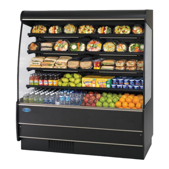
RSSM360, RSSD360, RSSM460, RSSD460,
RSSM560, RSSD560, RSSM660, RSSD660,
RSSM378, RSSD378, RSSM478, RSSD478,
RSSM578, RSSD578, RSSM678, RSSD678,
FEDERAL INDUSTRIES
Toll Free 1(800) 356-4206
Self-Contained & Remote Models
Includes Drop-In & NSSM
INSTALLATION & OPERATION
INSTRUCTIONS
KEEP THIS MANUAL FOR FUTURE REFERENCE
Engineering and technical data are subject to change without notice.
215 FEDERAL AVE
WI Phone (608) 424-3331
Belleville, WI 53508
Fax: (608) 424-3234
Advertisement
Table of Contents


Need help?
Do you have a question about the RSSM360 and is the answer not in the manual?
Questions and answers
Cómo serial temperatura