Table of Contents
Advertisement
Quick Links
Advertisement
Table of Contents

Subscribe to Our Youtube Channel
Related Manuals for BAYKON MX08


Summary of Contents for BAYKON MX08
- Page 1 MX08 Multichannel System Technical Manual...
-
Page 3: Table Of Contents
Calibration with test weights ..............40 5.3.2.4. eCal Electronic Calibration ................ 41 5.4. MX08 AD Status ....................42 5.5. Error Table......................43 5.6. Diagnostic Tests ....................44 MX08 DP Display ....................45 MX08 Multichannel Weighing System, Technical Manual, Rev. 2.5 Page 1 of 144... - Page 4 11.4.2. Ethernet Parameters on EtherX ............... 97 11.4.3. Ethernet Information ..................98 11.5. Modbus TCP/IP Data Structure ................98 11.6. Error Table......................106 11.7. Diagnostic Tests ....................107 MX08 Multichannel Weighing System, Technical Manual, Rev. 2.5 Page 2 of 144...
- Page 5 MX08 PL Setup ....................135 14.4.1. Powerlink Information ..................136 14.5. Powerlink Data Structure ................... 137 14.6. Error Table......................142 14.7. Diagnostic Tests ....................142 FAQ ........................144 MX08 Multichannel Weighing System, Technical Manual, Rev. 2.5 Page 3 of 144...
- Page 6 BAYKON reserves the right to revise this manual and alter its content without notification at any time. Neither BAYKON nor its affiliates shall be liable to the purchaser of this product or third parties for damages, losses, costs, or expenses incurred by purchaser or third parties as...
-
Page 7: Safety Instructions
OR DISCONNECTIONS ARE MADE. FAILURE TO OBSERVE THESE PRECAUTIONS COULD RESULT IN DAMAGE TO OR DESTRUCTION OF THE EQUIPMENT OR BODILY HARM. CAUTION OBSERVE PRECAUTIONS FOR HANDLING ELECTROSTATIC SENSITIVE DEVICES. MX08 Multichannel Weighing System, Technical Manual, Rev. 2.5 Page 5 of 144... -
Page 8: Declaration Of Conformity
EC Directive: Applicable Standards: Low Voltage Directive (LVD): (2014/35/EU) EN 60950-1:2008 Electromagnetic Compatibility (EMC): (2014/30/EU) EN 61326-1:2013 Baykon, January 2010 Sedat AYDEMİR Quality Assurance Manager MX08 Multichannel Weighing System, Technical Manual, Rev. 2.5 Page 6 of 144... -
Page 9: Introduction
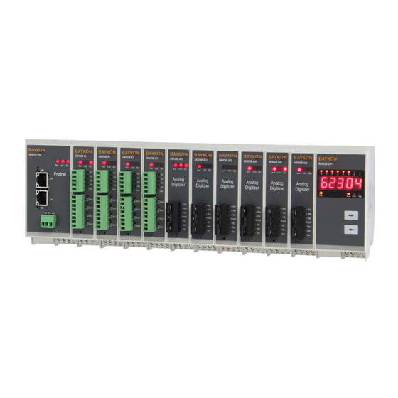
Input / Output unit and various gateways. MX08 family instruments are mounted on the DIN rail in the control cabinet and communicate each other by internal data bus which is named N-Bus. - Page 10 One of the most powerful instruments in this family is MX08 AD Analog Digitizer. It converts the low level strain gage load cell analog signal to high resolution and accurate digital signal.
-
Page 11: Key Features And Specifications
11 to 28 VDC max. 100 mA Environment and Enclosure: Operation temp.: -10 °C to +40 °C; 85% RH max, non-condensing Enclosure Polyamide, mounting in standard DIN rails, IP20 MX08 Multichannel Weighing System, Technical Manual, Rev. 2.5 Page 9 of 144... - Page 12 11 to 28 VDC max. 300 mA Environment and Enclosure: Operation temp.: -10 °C to +40 °C; 85% RH max, non-condensing Enclosure Polyamide, mounting in standard DIN rails, IP20 MX08 Multichannel Weighing System, Technical Manual, Rev. 2.5 Page 10 of 144...
- Page 13 11 to 28 VDC max. 100 mA Environment and Enclosure: Operation temp.: -10 °C to +40 °C; 85% RH max, non-condensing Enclosure Polyamide, mounting in standard DIN rails, IP20 MX08 Multichannel Weighing System, Technical Manual, Rev. 2.5 Page 11 of 144...
- Page 14 11 to 28 VDC max. 100 mA Environment and Enclosure: Operation temp.: -10 °C to +40 °C; 85% RH max, non-condensing Enclosure Polyamide, mounting in standard DIN rails, IP20 MX08 Multichannel Weighing System, Technical Manual, Rev. 2.5 Page 12 of 144...
-
Page 15: Housing
2.3. Housing MX08 housings are IP20, polyamide and easily mounting on NS 37/7 or NS 35/15 standard DIN rail. Drawings of the housing are seen below. 22,5 mm 45 mm 99 mm View A View B Side view √ √... -
Page 16: Accessories
The following accessories are supplied with the instrument or can be purchased separately. 2.4.1. Accessories supplied with the instrument The following accessories are supplied together with the MX08 instruments. If any part is missed, please contact to your supplier. 4-pos and 5mm pitch light gray plug for power connection... -
Page 17: Installation
Warning: Please care the following warnings for designing the control cabinet which will increase your system reliability. The control cabinet should be designed so that MX08 AD Analog Digitizer can operate safely. The panel should be placed clean area, not getting direct sun light if possible, with a temperature between -10 ºC and +40 ºC, humidity not exceeding 85% non-condensing. -
Page 18: Electrical Connections
Figure 2.2 - Din rail installation 3.3. Electrical Connections Warning: Please always remember that MX08 AD instruments are very low voltage measuring instruments. Your control cabinet design and proper installation increases reliability and performance of the instrument. Please do not forget that the instrument must be powered off before inserting or removing any peripheral connector. -
Page 19: Load Cell Connector
If you have junction box in your system, use 6 wire cable between MX08 AD and the junction box, and short circuit these pins at junction box for better performance. -
Page 20: Field Bus Connection
Warning: Connect the shield to the reference ground or shield pin of the power connector. 3.5. Digital I/O Connections MX08 IO unit has the input and output connectors on the front of the instrument. I/O connection diagram is shown in Figure 2.5. The outputs are free contact and the inputs are opto isolated. -
Page 21: Commissioning
Before power on the instrument, please make the required mechanical and electrical installations. After power on, you have to program your MX08 system before field bus interfacing. Install xFace to your PC as described in Section 3 Programming. xFace software is used for programming, calibration and testing of MX08 system. - Page 22 • After finishing the installation, the Setup Wizard will inform you the software is installed successfully and than click to “OK” button. Figure 3.4 – xFace installation step 4 MX08 Multichannel Weighing System, Technical Manual, Rev. 2.5 Page 20 of 144...
-
Page 23: Connection To Xface
After running xFace, select the instrument model you use. Select PC com port at connection settings menu in the tools tab and click the connect icon. The traffic lights of connect icon turns from red to green light when the communication is built between MX08 gateway instrument and your PC. -
Page 24: N-Bus Addressing Via Xface
Addressing Input/Output Instruments to N-Bus: First, click ‘Read’ button to read N- MAC numbers and addresses. Give an address to each MX08 IO. Then click ‘Write’ button to save the addressing settings. If the addressing MX08 IOs to N-Bus is completed successfully, I/O Status tab will be activated. -
Page 25: Gateway Setup
4.5. GSD/GSDML/EDS/ESI/XDD Configuration By default, Profibus, Profinet, EtherNet/IP, EtherCAT and Powerlink data structures of MX08 includes 8 pcs MX08 AD and 8 pcs MX08 IO. This is full configuration. MX08 Multichannel Weighing System, Technical Manual, Rev. 2.5 Page 23 of 144... - Page 26 Figure 3.9 - Full system GSD configuration Clicking “GSD/GSDML Configuration” in “Tool” menu opens the below window. Select quantity of MX08 AD and MX08 IO in your system and click to “Write new GSD/GSDML file”. This property would help to the PLC programmers to save time.
-
Page 27: Analog Digitizer Programming And Calibration
This will increase your weighing system performance by applying proper programming and calibration. MX08 AD Analog Digitizers shall be programmed in this sequence, if there is any analog digitizer in the system. First select the scale number you will program by pressing the scale selection buttons. -
Page 28: Analog Digitizer Performance Testing
You can find programming and calibration descriptions in Section 4.3. 4.7. Analog Digitizer Performance Testing MX08 AD performance testing is very important for assuring the stability, weighing speed, linearity, repeatability and eccentricity of the weighing system. During testing your system stability and weighing speed, you may change some parameter values for better performance by using Setup tab. -
Page 29: Digital Input/Output Tests
Figure 3.13 - I/O Status The active MX08 IO instruments are seen with its own N-Bus address block. You can follow inputs and outputs, and change outputs. I/O test property is very useful for checking the output states. -
Page 30: Back-Up Parameters And Calibration
4.10. Back-up Parameters and Calibration The parameter settings and calibration coefficients can be saved to the back up file after reading these data from MX08 instruments. This back up file can be written to MX08 instruments after opening it by xFace. -
Page 31: Bsi Data Structure
4.11. BSI Data Structure All new generation BAYKON instruments launched on the market support the standardized command set BSI data form, depending on the functionality of the instrument. This easy data format gives the reliable and speedy interface advantages with communicating PLC or PC for process control or transactional applications. - Page 32 [ADR][D][STATUS][SIGN][COUNT VALUE] Example Command : 12D Response : 12DD+00123400 or : 12DO (ADC out error) : 12DX (Not in count mode) Comments : Count value is send immediately. MX08 Multichannel Weighing System, Technical Manual, Rev. 2.5 Page 30 of 144...
- Page 33 Status must be stable in 2 seconds time out delay. If so, Ack is send. If it can not be stable in time out delay, Nack is send. MX08 Multichannel Weighing System, Technical Manual, Rev. 2.5 Page 31 of 144...
- Page 34 Data length change according to number of digital outputs. Outputs are implemented to ASCII char of 4-bit. ‘1111’ outputs are implemented to char ‘F’. OUTPUTS Bit wise ASCII MX08 Multichannel Weighing System, Technical Manual, Rev. 2.5 Page 32 of 144...
- Page 35 Checksum = 0 − (0x31 + 0x32 + 0x50 + 0x53 + 0x2B + 0x30 + 0x30 + 0x30 + 0x31+ 0x32 + 0x33 + 0x2E + 0x34) = 0 − 0xB9 = 0x47. CHK = Char ‘4’ and Char ‘7’ MX08 Multichannel Weighing System, Technical Manual, Rev. 2.5 Page 33 of 144...
-
Page 36: Mx08 Ad Analog Digitizer
5. MX08 AD A NALOG IGITIZER MX08 AD instrument is state-of-the-art strain gage load cell signal digitizer for weighing and force measurement. These instruments are used for any type of weighing processes and force measurement including tank and silo weighing, dynamic weighing, check weighing, filling, tension /compression force measurement etc. -
Page 37: Electrical Connection
In 4-wire installations the sense and excitation pins with the same polarity should be short circuited at the connector side. If you have junction box in your system, use 6 wire cable between MX08 AD and the junction box, and short circuit these pins at junction box for higher accuracy. -
Page 38: Programming And Calibration
5.3.1. Setup the Scale Parameters In setup menu, parameter values at MX08 AD can be seen, changed and saved to MX08 AD. These parameters are; Increased External Resolution This parameter enables to follow the weight value as 10 time higher resolution than programmed division in weighing and force mode for service engineer. - Page 39 AZT automatically re-adjusts the scale to zero for compensating defined small deviations around the center of zero. AZT is uses the range of zeroing and is not performed if this range is exceeded. (Not available in Count Mode) MX08 Multichannel Weighing System, Technical Manual, Rev. 2.5 Page 37 of 144...
-
Page 40: Calibration
Write to Digitizer: Click this button to save the operation mode and polarity to selected Digitizer. Scale setup Calibration block: This block allows the user to make calibration with test weights. MX08 Multichannel Weighing System, Technical Manual, Rev. 2.5 Page 38 of 144... -
Page 41: Mode Selection
Select scale operation mode and polarity. Click Write to Digitizer button to save your mode selection. Default calibration of MX08 AD instruments is Count Mode and 10 mV unipolar input signal range. If you select the count mode, there is no scale build and instrument calibration. Each MX08 AD instrument is adjusted in production to increase the calibration accuracy. -
Page 42: Calibration With Test Weights
Approximately 5 seconds later zero adjustment will be finalized. Note: Zero adjustment is also performed over field bus commands. Refer to data structure of related field bus. MX08 Multichannel Weighing System, Technical Manual, Rev. 2.5 Page 40 of 144... -
Page 43: Ecal Electronic Calibration
This feature is used to change Capacity/Increment without making re-calibration. 5.3.2.4. eCal Electronic Calibration eCal lets you to perform calibration without using test weights. MX08 AD is adjusted in production for increasing eCal accuracy. Calibration coefficients are calculated by scale capacity, total load cell capacity, load cell output and estimated dead load values. -
Page 44: Mx08 Ad Status
5.4. MX08 AD Status xFace status tab provides you information of count, gross, tare, net, indication, in zero range, error, serial number, firmware revisions of MX08 AD which have the selected address. Taring, Zeroing and Clear keys are located in this tab. -
Page 45: Error Table
5.5. Error Table The MX08 AD instruments have been designed as very reliable and virtually error free instruments. However if an error occurs do not attempt to repair the equipment before you understand what caused the error. Note the problems you have with your instrument and the error messages shown by the LEDs located on the front panel. -
Page 46: Diagnostic Tests
Light Flash Blank for 0.3 second Table 4.4 - Diagnostic test sequence Press programming switch for 5 seconds to exit diagnostic test mode and go to operation mode. MX08 Multichannel Weighing System, Technical Manual, Rev. 2.5 Page 44 of 144... -
Page 47: Mx08 Dp Display
6. MX08 DP D ISPLAY MX08 DP instrument is display unit for Analog Digitizers. One of Analog Digitizer’s weight/force or count data and stable, zero, net information are displayed. Also installed Analog Digitizers on the N-Bus are indicated with N-Bus address information. -
Page 48: Electrical Connection
30 seconds. Warning: Connect the grounding terminal to the reference ground. 24V 0V Figure 5.2 - Pin layout of MX08 DP 24VDC connector MX08 Multichannel Weighing System, Technical Manual, Rev. 2.5 Page 46 of 144... -
Page 49: Error Table
6.3. Error Table The MX08 instruments have been designed as very reliable and virtually error free instruments. However if an error occurs do not attempt to repair the equipment before you understand what caused the error. Note the problems you have with your instrument and the error messages shown by the LEDs located on the front panel. -
Page 50: Front View
NPUT UTPUT MX08 IO instrument has 4 opto-isolated digital inputs and 4 digital relay outputs. All over the I/O control is done over field bus communication or xFace connection. Refer to data structures of related gateway section for input output commands. For example, if Profibus is used for gateway communication, all input and output conditions are changed over Profibus commands. -
Page 51: Electrical Connection
7.2. Electrical Connection Digital I/O Connections MX08 IO unit has the input and output connectors on the front of the instrument. Figure 6.2 helps to user to make I/O connections. The outputs are free contact and the inputs are opto-isolated. -
Page 52: Mx08 Io Status
Figure 6.3 - Pin layout of MX08 IO 24 VDC connector 7.3. MX08 IO Status MX08 IO instruments are followed by xFace software which is connected via Gateway instrument. xFace status tab provides you information of input and output status. -
Page 53: Error Table
7.4. Error Table The MX08 IO instruments have been designed as very reliable and virtually error free instruments. However if an error occurs do not attempt to repair the equipment before you understand what caused the error. Note the problems you have with your instrument and the error messages shown by the LEDs located on the front panel. -
Page 54: Mx08 Mb Modbus Rtu Gateway
ODBUS ATEWAY MX08 MB gateway instrument integrates up to 8 pcs Analog Digitizer device and up to 8 pcs Input / Output device to Modbus-RTU field bus. MX08 MB instrument communicates with other MX08 instruments via internal data bus N-Bus and responses to the PLC very fast via Modbus RTU. -
Page 55: Electrical Connection
RS-485 and RS-232C and power supply terminals pin configurations are shown in Figure 7.2. Figure 7.2 MX08 MB serial interface connections RS-232C Serial interface Interfacing with PC, programming the MX08 system ( xFace ), Usage BSI interface with PC or PLC. BSI (*) (Refer to Section 3.11) Data formats Modbus RTU High-Low (Refer to Section 7.5) -
Page 56: N-Bus Addressing
8.3. N-Bus Addressing MX08 instruments communicate each other over internal data bus which is called N-Bus. MX08 gateway instrument is master of N-Bus. All other instruments are slave and shall be addressed to gateway. N-Bus addressing can be done by using xFace PC software (refer to Section 3.3) or via programming switch (refer to Section 3.9). -
Page 57: Modbus Rtu Parameters
RS-232C Checksum The checksum can be enabled or disabled from BSI data format. The checksum calculation can be found in the related data format description. Default is ‘Enable’. MX08 Multichannel Weighing System, Technical Manual, Rev. 2.5 Page 55 of 144... - Page 58 RS-485 Data Length & Parity The data length and parity can be selected as 8 None 1, 7 Odd 1 or 7 Even 1. Default is ‘8 None 1’. MX08 Multichannel Weighing System, Technical Manual, Rev. 2.5 Page 56 of 144...
-
Page 59: Modbus Information
Firmware Date: Generated firmware date Hardware Version: Revision number of main pcb board. Serial Number: Instrument’s serial number. Gateway Status: Follow the status whether the system is proper or not. MX08 Multichannel Weighing System, Technical Manual, Rev. 2.5 Page 57 of 144... -
Page 60: Modbus Rtu Data Structure
: 01, 03, 04, 00, 00, 27, 10, E0, 0F Indicated : 2710 hex (10000 dec) Status, Indicated, Gross and Tare values of MX08 AD [0] at register 41005 - 41011. Request : 01, 03, 03, EC, 00, 07, C5, B9... - Page 61 Request : 01, 03, 04, 66, 00, 01, 65, 25 (Read status; it must be in ready status) Answer : 01, 03, 02, 00, 01, 79, 84 (MX08 AD [0] is in ready status; zero calibration can be performed) Request...
- Page 62 MX08 MB Modbus RTU Command Set 1: The below register table is used for MX08 AD[0]. Address Word Command Description 40001 Weight / Force / Count Data 0 – System Ready 1 – System Busy 0 – Error 1 – Data ok 0 –...
- Page 63 40034 Power increment. For example: 23.4 VDC is indicated as 234 Supply value. All MX08 AD uses the same register table like above. Starting register address of all MX08 AD: MX08 AD[0]: 40001 MX08 AD[1]: 40101 MX08 AD[2]: 40201 MX08 AD[3]: 40301...
- Page 64 IO [7] 10 = 7 addressed 8I is active 11 = 7 addressed 8O is active System fail MX08 MB 41003 Gateway Eeprom fail Status Field bus communication error MX08 Multichannel Weighing System, Technical Manual, Rev. 2.5 Page 62 of 144...
- Page 65 MX08 AD [5] Gross Weight 41045 MX08 AD [5] Tare Weight 41047 MX08 AD [6] Status 41048 MX08 AD [6] Indicated Weight 41050 MX08 AD [6] Gross Weight MX08 Multichannel Weighing System, Technical Manual, Rev. 2.5 Page 63 of 144...
- Page 66 MX08 AD [1] Indicated Weight 41086 MX08 AD [2] Status 41087 MX08 AD [2] Indicated Weight 41089 MX08 AD [3] Status 41090 MX08 AD [3] Indicated Weight 41092 MX08 AD [4] Status MX08 Multichannel Weighing System, Technical Manual, Rev. 2.5 Page 64 of 144...
- Page 67 MX08 AD [7] Indicated Weight 41104 Not used 0 – Out of Zero R. 1 – In Zero Range MX08 0 – Weight Stable 1– Unstable 0 – Out of Zero R. 1 – In Zero Range MX08 0 – Weight Stable 1– Unstable 0 –...
-
Page 68: Error Table
8.6. Error Table The MX08 MB gateway instruments have been designed as very reliable and virtually error free instruments. However if an error occurs do not attempt to repair the equipment before you understand what caused the error. Note the problems you have with your instrument and the error messages shown by the LEDs located on the front panel. -
Page 69: Diagnostic Tests
If you short circuit RXD and TXD pins on RS-232C port and go in to TxD test, the receiving data is shown by Pwr LED. Press programming switch for 5 seconds to exit diagnostic test mode and go to operation mode. MX08 Multichannel Weighing System, Technical Manual, Rev. 2.5 Page 67 of 144... -
Page 70: Mx08 Pb Profibus Dp Gateway
ROFIBUS ATEWAY MX08 PB gateway instrument integrates up to 8 pcs Analog Digitizer device and up to 8 pcs Input / Output device to Profibus field bus. MX08 PB instrument communicates with other MX08 instruments via internal data bus N-Bus and responses to the PLC very fast via Profibus. - Page 71 Comment Not online /No power Check power and cable Green On-line, data exchange Flashing Green On-line, clear Flashing Red PROFIBUS configuration error Check GSD file configuration. (2 flash) MX08 Multichannel Weighing System, Technical Manual, Rev. 2.5 Page 69 of 144...
-
Page 72: Electrical Connections
+5V termination power (isolated) A Line Negative RxD / TxD, RS-485 level Housing Cable Shield Ground Figure 8.2 - MX08 PB serial interface connections RS-232C Serial interface Usage Used for service port (xFace) Baud rate 9600 bps Length and parity... -
Page 73: N-Bus Addressing
9.3. N-Bus Addressing MX08 instruments communicate each other over internal data bus which is called N-Bus. MX08 gateway instrument is master of N-Bus. All other instruments are slave and shall be addressed to gateway. N-Bus addressing can be done by using xFace PC software (Refer to Section 3.3) or via programming switch (Section 3.9). -
Page 74: Profibus Dp Parameters
Serial Number: Instrument’s serial number. Gateway Status: Follow the status whether the system is proper or not. GSD Configuration: Max. quantity of MX08 AD and MX08 IO instruments in the system. MX08 Multichannel Weighing System, Technical Manual, Rev. 2.5 Page 72 of 144... -
Page 75: Profibus Dp Data Structure
− Re-address the instruments on N-Bus (Refer to section 3.3 or 0101 Section 3.9 N-Bus addressing) D11…D1 Not in use Toggles The command is applied successfully CMD Flag MX08 Multichannel Weighing System, Technical Manual, Rev. 2.5 Page 73 of 144... - Page 76 00011 Indicated weight (floating point type) 00101 Tare weight (floating point type) 10000 Calibration Status (Refer to below table) Toggles The command is applied successfully CMD Flag MX08 Multichannel Weighing System, Technical Manual, Rev. 2.5 Page 74 of 144...
- Page 77 , 10 , 12 , 14 , 16 Dword descriptions when Read Command is ‘Calibration Number Status’. Refer to PLC Output to MX08 PB Input for 3 Dword … Not in use Calibration Timeout 0000 0001 - Restart calibration ADC Error...
- Page 78 Dword Description D31 … D9 Not in use 0: Input / Outputs change over PLC Output to MX08 PB Input I/O Bytes. This flag does not need to New CMD command. Write 1: Input / Outputs are change over Common Command List below.
- Page 79 Output 4 Output 3 Output 2 Output 1 MX08 IO[6] +7 Byte (W) Output 4 Output 3 Output 2 Output 1 MX08 IO[7] +8 Byte (W) Output 4 Output 3 Output 2 Output 1 MX08 Multichannel Weighing System, Technical Manual, Rev. 2.5 Page 77 of 144...
-
Page 80: Error Table
9.6. Error Table The MX08 PB gateway instruments have been designed as very reliable and virtually error free instruments. However if an error occurs do not attempt to repair the equipment before you understand what caused the error. Note the problems you have with your instrument and the error messages shown by the LEDs located on the front panel. -
Page 81: Diagnostic Tests
If you short circuit RXD and TXD pins on RS-232C port and go in to TxD test, the receiving data is shown by Pwr LED. Press programming switch for 5 seconds to exit diagnostic test mode and go to operation mode. MX08 Multichannel Weighing System, Technical Manual, Rev. 2.5 Page 79 of 144... -
Page 82: Mx08 Pn Profinet Gateway
ROFINET ATEWAY MX08 PN gateway instrument integrates up to 8 pcs Analog Digitizer device and up to 8 pcs Input / Output device to Profinet field bus. MX08 PN instrument communicates with other MX08 instruments via internal data bus N-Bus and responses to the PLC very fast via Profinet. - Page 83 The meanings of the annunciater LEDs in operation are given below. Symbol Name MX08 PN is not powered. Check power cable. Power MX08 PN is powered. No data transmission done. Link Data transmission done to xFace or Modbus-RTU No Error found.
-
Page 84: Electrical Connections
On-line (RUN) Green, flashing On-line (STOP) 10.2. Electrical Connections Profinet, RS-232C and power supply terminals are shown in Figure 9.1. Figure 9.2 - MX08 PN serial interface connections RS-232C Serial interface Usage Used for service port (xFace) Baud rate 9600 bps... -
Page 85: N-Bus Addressing
10.3. N-Bus Addressing MX08 instruments communicate each other over internal data bus which is called N-Bus. MX08 gateway instrument is master of N-Bus. All other instruments are slave and shall be addressed to gateway. N-Bus addressing can be done by using xFace PC software (Refer to Section 3.3) or via programming switch (Section 3.9). -
Page 86: Profinet Parameters On Etherx
Serial Number: Instrument’s serial number. Gateway Status: Follow the status whether the system is proper or not. GSDML Configuration: Max. quantity of MX08 AD and MX08 IO instruments in the system. MX08 Multichannel Weighing System, Technical Manual, Rev. 2.5 Page 84 of 144... -
Page 87: Profinet Data Structure
− Re-address the instruments on N-Bus (Refer to section 3.3 or 0101 Section 3.9 N-Bus addressing) D11…D1 Not in use Toggles The command is applied successfully CMD Flag MX08 Multichannel Weighing System, Technical Manual, Rev. 2.5 Page 85 of 144... - Page 88 00011 Indicated weight (floating point type) 00101 Tare weight (floating point type) 10000 Calibration Status (Refer to below table) Toggles The command is applied successfully CMD Flag MX08 Multichannel Weighing System, Technical Manual, Rev. 2.5 Page 86 of 144...
- Page 89 , 10 , 12 , 14 , 16 Dword descriptions when Read Command is ‘Calibration Number Status’. Refer to PLC Output to MX08 PN Input for 3 Dword … Not in use Calibration Timeout 0000 0001 - Restart calibration ADC Error...
- Page 90 Dword Description D31 … D9 Not in use 0: Input / Outputs change over PLC Output to MX08 PN Input I/O Bytes. This flag does not need to New CMD command. Write 1: Input / Outputs are change over Common Command List below.
- Page 91 Output 4 Output 3 Output 2 Output 1 MX08 IO[6] +7 Byte (W) Output 4 Output 3 Output 2 Output 1 MX08 IO[7] +8 Byte (W) Output 4 Output 3 Output 2 Output 1 MX08 Multichannel Weighing System, Technical Manual, Rev. 2.5 Page 89 of 144...
-
Page 92: Error Table
10.6. Error Table The MX08 PN gateway instruments have been designed as very reliable and virtually error free instruments. However if an error occurs do not attempt to repair the equipment before you understand what caused the error. Note the problems you have with your instrument and the error messages shown by the LEDs located on the front panel. -
Page 93: Diagnostic Tests
If you short circuit RXD and TXD pins on RS-232C port and go in to TxD test, the receiving data is shown by Pwr LED. Press programming switch for 5 seconds to exit diagnostic test mode and go to operation mode. MX08 Multichannel Weighing System, Technical Manual, Rev. 2.5 Page 91 of 144... -
Page 94: Mx08 En Ethernet Gateway
THERNET ATEWAY MX08 EN gateway instrument integrates up to 8 pcs Analog Digitizer device and up to 8 pcs Input / Output device to Ethernet field bus. MX08 EN instrument communicates with other MX08 instruments via internal data bus N-Bus and responses to the PLC very fast via Ethernet. -
Page 95: Electrical Connections
The meanings of the annunciater LEDs in operation are given below. Symbol Name MX08 EN is not powered. Check power cable. Power MX08 EN is powered. No data transmission done. Link Data transmission done to xFace or Modbus TCP/IP No Error found. - Page 96 MX08 EN serial interface connections are shown below: Figure 10.4 - MX08 EN serial interface connections RS-232C Serial interface Usage Interfacing with PC and PLC, programming the MX08 (xFace) Data formats BSI, Modbus RTU High-Low, Modbus RTU Low-High Baud rate...
-
Page 97: N-Bus Addressing
11.3. N-Bus Addressing MX08 instruments communicate each other over internal data bus which is called N-Bus. MX08 gateway instrument is master of N-Bus. All other instruments are slave and shall be addressed to gateway. N-Bus addressing can be done by using xFace PC software (Refer to Section 3.3) or via programming switch (Section 3.9). -
Page 98: Interface Parameters
Communicates in BSI data format as a slave. Refer to ‘Refer to Section 3.11’ for details. Modbus TCP/IP Modbus TCP/IP communication. Refer to Section 10.5 for details. High-Low MX08 Multichannel Weighing System, Technical Manual, Rev. 2.5 Page 96 of 144... -
Page 99: Ethernet Parameters On Etherx
Describes IP address can be used in network. Default is ‘255.255.255.0’. Primary DNS Obtain primary DNS manually. Default is ‘208.67.222.222’. Secondary DNS Obtain secondary DNS manually. Default is ‘208.67.220.220’. MX08 Multichannel Weighing System, Technical Manual, Rev. 2.5 Page 97 of 144... -
Page 100: Ethernet Information
Please find Modbus information in the web site of http://www.modbus.org Examples: Performing Read and Write operations according to hex system with the MX08 EN set to address ‘0x01’. MBAP (Modbus Application Protocol) Header is not included to the below Modbus TCP/IP application data units. - Page 101 Request : 03, 04, 66, 00, 01 (Read status; it must be in ready status) Answer : 03, 02, 00, 01 (MX08 AD [0] is in ready status; zero calibration can be performed) Request : 10, 04, 63, 00, 01, 02, 00, BC (Zero calibration command)
- Page 102 2 : Received data address is not in allowable address range 3 : Invalid value entrance or wrong byte number 4 : Operation error MX08 EN Modbus TCP/IP Command Set 1: The below register table is used for MX08 AD[0]. Address Word Command Description...
- Page 103 Count Mode 18 mV Fast Digital 40016 Filters Slow All MX08 AD uses the same register table like above. Starting register address of all MX08 AD: MX08 AD[0]: 40001 MX08 AD[1]: 40101 MX08 AD[2]: 40201 MX08 AD[3]: 40301 MX08 AD[4]: 40401...
- Page 104 11 = 7 addressed 8O is active System fail Eeprom fail MX08 MB 41003 Gateway Field bus communication error Status An instrument is installed/removed in/from system Any instrument is not found in system MX08 Multichannel Weighing System, Technical Manual, Rev. 2.5 Page 102 of 144...
- Page 105 MX08 AD [5] Indicated Weight 41043 MX08 AD [5] Gross Weight 41045 MX08 AD [5] Tare Weight 41047 MX08 AD [6] Status 41048 MX08 AD [6] Indicated Weight MX08 Multichannel Weighing System, Technical Manual, Rev. 2.5 Page 103 of 144...
- Page 106 MX08 AD [0] Indicated Weight 41083 MX08 AD [1] Status 41084 MX08 AD [1] Indicated Weight 41086 MX08 AD [2] Status 41087 MX08 AD [2] Indicated Weight 41089 MX08 AD [3] Status MX08 Multichannel Weighing System, Technical Manual, Rev. 2.5 Page 104 of 144...
- Page 107 MX08 AD [3] Indicated Weight 41115 MX08 AD [4] Indicated Weight 41117 MX08 AD [5] Indicated Weight 41119 MX08 AD [6] Indicated Weight 41121 MX08 AD [7] Indicated Weight MX08 Multichannel Weighing System, Technical Manual, Rev. 2.5 Page 105 of 144...
-
Page 108: Error Table
11.6. Error Table The MX08 EN gateway instruments have been designed as very reliable and virtually error free instruments. However if an error occurs do not attempt to repair the equipment before you understand what caused the error. Note the problems you have with your instrument and the error messages shown by the LEDs located on the front panel. -
Page 109: Diagnostic Tests
If you short circuit RXD and TXD pins on RS-232C port and go in to TxD test, the receiving data is shown by Pwr LED. Press programming switch for 5 seconds to exit diagnostic test mode and go to operation mode. MX08 Multichannel Weighing System, Technical Manual, Rev. 2.5 Page 107 of 144... -
Page 110: Mx08 Ei Ethernet/Ip Gateway
THER ATEWAY MX08 EI gateway instrument integrates up to 8 pcs Analog Digitizer device and up to 8 pcs Input / Output device to EtherNet/IP field bus. MX08 EI instrument communicates with other MX08 instruments via internal data bus N-Bus and responses to the PLC very fast via EtherNet/IP. - Page 111 The meanings of the annunciater LEDs in operation are given below. Symbol Name MX08 EI is not powered. Check power cable. Power MX08 EI is powered. No data transmission done. Link Data transmission done to xFace or Modbus-RTU No Error found.
-
Page 112: Electrical Connections
One or more connections timed out (CIP Class 1 or 3) 12.2. Electrical Connections EtherNet/IP, RS-232C and power supply terminals are shown in Figure 11.1. Figure 11.2 - MX08 EI serial interface connections RS-232C Serial interface Usage Used for service port (xFace) -
Page 113: N-Bus Addressing
12.4. MX08 EI Setup MX08 gateway set up is done by xFace software as described in this section. Connect MX08 EI instrument to your PC via RS-232C service port on the instrument as indicated in Figure 11.2. Select Gateway tab after connecting xFace to MX08 EI. Gateway tab is seen in figure below. - Page 114 Serial Number: Instrument’s serial number. Gateway Status: Follow the status whether the system is proper or not. EDS Configuration: Max. quantity of MX08 AD and MX08 IO instruments in the system. MX08 Multichannel Weighing System, Technical Manual, Rev. 2.5 Page 112 of 144...
-
Page 115: Ethernet/Ip Data Structure
− Re-address the instruments on N-Bus (Refer to section 3.3 or 0101 Section 3.9 N-Bus addressing) D11…D1 Not in use Toggles The command is applied successfully CMD Flag MX08 Multichannel Weighing System, Technical Manual, Rev. 2.5 Page 113 of 144... - Page 116 00011 Indicated weight (floating point type) 00101 Tare weight (floating point type) 10000 Calibration Status (Refer to below table) Toggles The command is applied successfully CMD Flag MX08 Multichannel Weighing System, Technical Manual, Rev. 2.5 Page 114 of 144...
- Page 117 , 10 , 12 , 14 , 16 Dword descriptions when Read Command is ‘Calibration Number Status’. Refer to PLC Output to MX08 EI Input for 3 Dword … Not in use Calibration Timeout 0000 0001 - Restart calibration ADC Error...
- Page 118 Dword Description D31 … D9 Not in use 0: Input / Outputs change over PLC Output to MX08 EI Input I/O Bytes. This flag does not need to New CMD command. Write 1: Input / Outputs are change over Common Command List below.
- Page 119 Output 4 Output 3 Output 2 Output 1 MX08 IO[6] +7 Byte (W) Output 4 Output 3 Output 2 Output 1 MX08 IO[7] +8 Byte (W) Output 4 Output 3 Output 2 Output 1 MX08 Multichannel Weighing System, Technical Manual, Rev. 2.5 Page 117 of 144...
-
Page 120: Error Table
12.6. Error Table The MX08 EI gateway instruments have been designed as very reliable and virtually error free instruments. However if an error occurs do not attempt to repair the equipment before you understand what caused the error. Note the problems you have with your instrument and the error messages shown by the LEDs located on the front panel. - Page 121 If you short circuit RXD and TXD pins on RS-232C port and go in to TxD test, the receiving data is shown by Pwr LED. Press programming switch for 5 seconds to exit diagnostic test mode and go to operation mode. MX08 Multichannel Weighing System, Technical Manual, Rev. 2.5 Page 119 of 144...
-
Page 122: Mx08 Ec Ethercat Gateway
THER ATEWAY MX08 EC gateway instrument integrates up to 8 pcs Analog Digitizer device and up to 8 pcs Input / Output device to EtherCAT field bus. MX08 EC instrument communicates with other MX08 instruments via internal data bus N-Bus and responses to the PLC very fast via EtherCAT. - Page 123 The meanings of the annunciater LEDs in operation are given below. Symbol Name MX08 EC is not powered. Check power cable. Power MX08 EC is powered. No data transmission done. Link Data transmission done to xFace or Modbus-RTU No Error found.
-
Page 124: Electrical Connections
Red, double flash Application watchdog timeout Application controller failure 13.2. Electrical Connections EtherCAT, RS-232C and power supply terminals are shown in Figure 12.1. Figure 12.2 - MX08 EC serial interface connections RS-232C Serial interface Usage Used for service port (xFace) Baud rate... -
Page 125: N-Bus Addressing
13.3. N-Bus Addressing MX08 instruments communicate each other over internal data bus which is called N-Bus. MX08 gateway instrument is master of N-Bus. All other instruments are slave and shall be addressed to gateway. N-Bus addressing can be done by using xFace PC software (Refer to Section 3.3) or via programming switch (Section 3.9). - Page 126 Serial Number: Instrument’s serial number. Gateway Status: Follow the status whether the system is proper or not. ESI Configuration: Max. quantity of MX08 AD and MX08 IO instruments in the system. MX08 Multichannel Weighing System, Technical Manual, Rev. 2.5 Page 124 of 144...
-
Page 127: Ethercat Data Structure
− Re-address the instruments on N-Bus (Refer to section 3.3 or 0101 Section 3.9 N-Bus addressing) D11…D1 Not in use Toggles The command is applied successfully CMD Flag MX08 Multichannel Weighing System, Technical Manual, Rev. 2.5 Page 125 of 144... - Page 128 00011 Indicated weight (floating point type) 00101 Tare weight (floating point type) 10000 Calibration Status (Refer to below table) Toggles The command is applied successfully CMD Flag MX08 Multichannel Weighing System, Technical Manual, Rev. 2.5 Page 126 of 144...
- Page 129 , 10 , 12 , 14 , 16 Dword descriptions when Read Command is ‘Calibration Number Status’. Refer to PLC Output to MX08 EC Input for 3 Dword … Not in use Calibration Timeout 0000 0001 - Restart calibration ADC Error...
- Page 130 Dword Description D31 … D9 Not in use 0: Input / Outputs change over PLC Output to MX08 EC Input I/O Bytes. This flag does not need to New CMD command. Write 1: Input / Outputs are change over Common Command List below.
- Page 131 Output 4 Output 3 Output 2 Output 1 MX08 IO[6] +7 Byte (W) Output 4 Output 3 Output 2 Output 1 MX08 IO[7] +8 Byte (W) Output 4 Output 3 Output 2 Output 1 MX08 Multichannel Weighing System, Technical Manual, Rev. 2.5 Page 129 of 144...
-
Page 132: Error Table
13.6. Error Table The MX08 EC gateway instruments have been designed as very reliable and virtually error free instruments. However if an error occurs do not attempt to repair the equipment before you understand what caused the error. Note the problems you have with your instrument and the error messages shown by the LEDs located on the front panel. - Page 133 If you short circuit RXD and TXD pins on RS-232C port and go in to TxD test, the receiving data is shown by Pwr LED. Press programming switch for 5 seconds to exit diagnostic test mode and go to operation mode. MX08 Multichannel Weighing System, Technical Manual, Rev. 2.5 Page 131 of 144...
-
Page 134: Mx08 Pl Powerlink Gateway
OWERLINK ATEWAY MX08 PL gateway instrument integrates up to 8 pcs Analog Digitizer device and up to 8 pcs Input / Output device to Powerlink field bus. MX08 PL instrument communicates with other MX08 instruments via internal data bus N-Bus and responses to the PLC very fast via Powerlink. - Page 135 The meanings of the annunciater LEDs in operation are given below. Symbol Name MX08 PL is not powered. Check power cable. Power MX08 PL is powered. No data transmission done. Link Data transmission done to xFace or Modbus-RTU No Error found.
-
Page 136: Electrical Connections
If the STATUS LED is red, a fatal event was encountered. 14.2. Electrical Connections Powerlink, RS-232C and power supply terminals are shown in Figure 13.1. Figure 13.2 - MX08 PL serial interface connections RS-232C Serial interface Usage Used for service port (xFace) -
Page 137: N-Bus Addressing
14.4. MX08 PL Setup MX08 gateway set up is done by xFace software as described in this section. Connect MX08 PL instrument to your PC via RS-232C service port on the instrument as indicated in Figure 13.2. Select Gateway tab after connecting xFace to MX08 PL. Gateway tab is seen in figure below. -
Page 138: Powerlink Information
Serial Number: Instrument’s serial number. Gateway Status: Follow the status whether the system is proper or not. XDD Configuration: Max. quantity of MX08 AD and MX08 IO instruments in the system. MX08 Multichannel Weighing System, Technical Manual, Rev. 2.5 Page 136 of 144... -
Page 139: Powerlink Data Structure
− Re-address the instruments on N-Bus (Refer to section 3.3 or 0101 Section 3.9 N-Bus addressing) D11…D1 Not in use Toggles The command is applied successfully CMD Flag MX08 Multichannel Weighing System, Technical Manual, Rev. 2.5 Page 137 of 144... - Page 140 00011 Indicated weight (floating point type) 00101 Tare weight (floating point type) 10000 Calibration Status (Refer to below table) Toggles The command is applied successfully CMD Flag MX08 Multichannel Weighing System, Technical Manual, Rev. 2.5 Page 138 of 144...
- Page 141 , 10 , 12 , 14 , 16 Dword descriptions when Read Command is ‘Calibration Number Status’. Refer to PLC Output to MX08 PL Input for 3 Dword … Not in use Calibration Timeout 0000 0001 - Restart calibration ADC Error...
- Page 142 Dword Description D31 … D9 Not in use 0: Input / Outputs change over PLC Output to MX08 PL Input I/O Bytes. This flag does not need to New CMD command. Write 1: Input / Outputs are change over Common Command List below.
- Page 143 Output 4 Output 3 Output 2 Output 1 MX08 IO[6] +7 Byte (W) Output 4 Output 3 Output 2 Output 1 MX08 IO[7] +8 Byte (W) Output 4 Output 3 Output 2 Output 1 MX08 Multichannel Weighing System, Technical Manual, Rev. 2.5 Page 141 of 144...
-
Page 144: Error Table
14.6. Error Table The MX08 PL gateway instruments have been designed as very reliable and virtually error free instruments. However if an error occurs do not attempt to repair the equipment before you understand what caused the error. Note the problems you have with your instrument and the error messages shown by the LEDs located on the front panel. - Page 145 If you short circuit RXD and TXD pins on RS-232C port and go in to TxD test, the receiving data is shown by Pwr LED. Press programming switch for 5 seconds to exit diagnostic test mode and go to operation mode. MX08 Multichannel Weighing System, Technical Manual, Rev. 2.5 Page 143 of 144...
-
Page 146: Faq
65 conversion/second. Question : How can I check Ethernet connection? : − MX08 EN has a dummy web page. You can easily open web page with any Answer browser installed on any PC in network. - Page 148 BAYKON A.Ş. Kimya Sanayicileri Organize Sanayi Bölgesi Organik Cad. No:31 Tepeören, 34956 İstanbul, TURKEY Tel : 0216 593 26 30 (pbx) Fax : 0216 593 26 38 e-mail: baykonservis@baykon.com http:// www.baykon.com...
Need help?
Do you have a question about the MX08 and is the answer not in the manual?
Questions and answers