Table of Contents
Advertisement
Advertisement
Table of Contents

Subscribe to Our Youtube Channel
Related Manuals for BAYKON TX 1


Summary of Contents for BAYKON TX 1
- Page 1 T X 1 WEIGHT TRANSMITTER OPERATIONAL MANUAL 08/2012...
-
Page 2: Table Of Contents
Don’t connect / disconnect the cables and/or connectors while TX 1 is energized. Do not open the enclosure while TX 1 is connected to the power supply. WARNING ! The Error LED can be active before calibration. Do not care the error status... -
Page 3: Features
Analogue output goes out of the operating range. • Via optional zeroing input, TX 1 can be zeroed by PLC or any other external device. • eCal calibration and setup without weights via optional serial port and PC software. -
Page 4: Installation And Commissioning
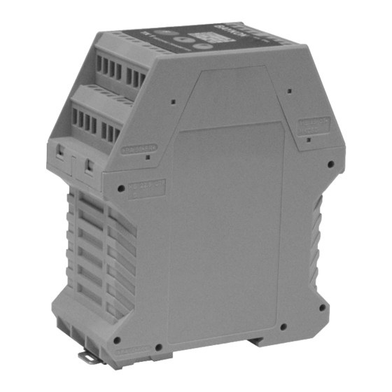
The pin layout of TX 1 is shown below. Electrical connections should be done carefully. TX 1 requires a power supply of 230 VAC, 50 Hz and 6 VA ( Figure 1 ) or 24 VDC 0.2 A ( Figure 2 ) to operate. -
Page 5: Load Cell Connection
24 VDC Not Connected Figure 2. TX 1 24 VDC front view and pin layout Do not forget to connect the shield of the load cell cable and the analogue output cable to TX 1 at the correct ground terminals. -
Page 6: Analogue Output Connection
2.4. Analogue Output Connection There are 2 analogue outputs on TX 1; one is for 0 – 10 volt and the other for 4 – 20 mA. But only one of them can be used at the same time and has to be selected in the setup mode. -
Page 7: Commissioning
2.7. Commissioning After making the connections of TX 1 as described above, energize TX 1 carefully. Then set the instrument to the desired output mode and perform the setup and calibration operations as described in Section 4. Check the performance of your system with different test weights. -
Page 8: Changing The Analogue Output Mode
In this Section you’ll find the required information for the setup and the calibration of TX 1. The symbols at the right bottom of the keys show the function of the keys in setup mode. - Page 9 STEPS LED’s POSITION DESCRIPTION GREEN Unload the scale and check analog output value : ZERO ADJUST : Analog output value is set as automatically to 0 VDC or 4 mA when pressed this key. Flash Flash Load the scale. The load value must be between 10% to 100% of your maximum and check analog output value : SPAN ADJUST Flash...
- Page 10 STEPS LED’s POSITION DESCRIPTION GREEN Unload the scale. Adjust the output value to 0 V or 4 mA by using keys ZERO ADJUST ZERO ADJUST described below : Flash : Pressing this key will decrease the output value. Pressing this key (BLINKS) ( OFF) continuously will decrease output faster.
-
Page 11: Programming By Pc Software
5. Programming by PC Software TX 1W has RS232C serial interface, you can perform eCal electronic calibration, adjust filter, download setpoint values and follow status by using xFace software installed on a You can make eCal easily by entering total load cell capacity in kg, load cell output in mV/V, scale capacity in kg and estimated preload values to the eCal window and clicking “write eCal values to the transmitter”... -
Page 12: Housing Dimensions
6. Housing Dimensions 7. Trouble Shooting The type TX 1 amplifier has been designed as a very reliable and virtually error free instrument. However if an error occurs, do not attempt to repair the equipment before you understand what caused the error. Note the status of the front panel LEDs, and try to find the problem with the help of the table given below. - Page 13 Notes :...
- Page 14 BAYKON A.Ş. Kimya Sanayicileri Organize Sanayi Bölgesi Organik Cad. No:31 Tepeören, 34956 İstanbul, TÜRKİYE Tel : 0216 593 26 30 (pbx) Fax : 0216 593 26 38 e-mail: baykonservis@baykon.com http:// www.baykon.com...
Need help?
Do you have a question about the TX 1 and is the answer not in the manual?
Questions and answers