
Related Manuals for Velleman High-Q-kit K8051


Summary of Contents for Velleman High-Q-kit K8051
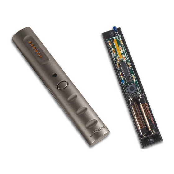
- Page 1 Total solder points: 66 Difficulty level: beginner 1 advanced 15 Channel IR remote stick K8051 ILLUSTRATED ASSEMBLY MANUAL H8051IP-1...
- Page 2 Features & Specifications Features: Slim designer enclosure. 2-button operation. Built-in ‘all clear’ function 3 addresses with 15 channels each. Easy channel and address selection. Compatible with most current and upcoming IR kits. Low power consumption. Specifications: • Power supply : 2 x AAA battery (not included). •...
- Page 3 Assembly hints 1. Assembly (Skipping this can lead to troubles ! ) Ok, so we have your attention. These hints will help you to make this project successful. Read them carefully. 1.1 Make sure you have the right tools: • A good quality soldering iron (25-40W) with a small tip.
- Page 4 Assembly hints 1.3 Soldering Hints : 1- Mount the component against the PCB surface and carefully solder the leads 2- Make sure the solder joints are cone-shaped and shiny 3- Trim excess leads as close as possible to the solder joint REMOVE THEM FROM THE TAPE ONE AT A TIME ! AXIAL COMPONENTS ARE TAPED IN THE COR- RECT MOUNTING SEQUENCE !
- Page 5 Construction 1. Resistors 3. Push button 5. Transistor T1 : BC639 R... SW1 : Transmit (KRS1243) R1 : 4E7 (4-7-B-B) R2 : 330 (3-3-1-B) R3 : 330 (3-3-1-B) 4. IC socket, Watch the po- 6. IC mounting R4 : 330 (3-3-1-B) sition of the notch! R5 : 330...
- Page 6 Construction 7. Mounting the LED readout 1. Stick a piece of tape over the LED mounting holes. This allows you to level the LEDs before soldering them.(see fig. 1.0). FIG 1.0 Complete the assembly as follows : 2. Insert the LEDs BUT DO NOT SOLDER THEM YET! Mind the polarity ! (fig 2.0) FIG 2.0 CATHODE...
- Page 7 Construction 3. Flip the PCB and guide all LEDs trough their holes (fig 3.0). => Make sure that all LEDs touch the tape! FIG 3.0 4. Solder the connections (fig 4.0). FIG 4.0 5. Remove the tape.
- Page 8 Enclosure preparation 8. Enclosure preparation 2 Holes must be drilled into the enclosure. Follow next steps exactly! Pay attention to the correct diameter. Make sure the holes are free of burrs. STEP 1 Drawing 5.0 provides a drill pattern for the ‘select’ button. •...
- Page 9 Enclosure preparation STEP 2 Drawing 7.0 provides a drill pattern for the IR-LED. • Close the enclosure with the 2 supplied screws. Mark the centre of the hole to be drilled on the top of the enclosure (Fig 6.0). Make sure that the centre of the hole is in the middle of the housing and 7mm from the left hand side (Fig 7.0) Dia 5.5 BOTTOM...
- Page 10 Mounting the PCB 9. Mounting the PCB STEP 1 Mount the ‘select’ push button. (SW2)
- Page 11 Mounting the PCB STEP 2 Mount the infrared LED (mounting height: 20mm) (fig 8.0). 20mm CATHO DE D7 : L-53F3BT (blue) FIG 8.0 Jumpers STEP 3 Solder two jumperwires ( - & +).
- Page 12 Mounting the PCB STEP 4 Place the battery contacts. Pay attention to the polarity ! (Fig 9.0) FIG 9.0...
- Page 13 Mounting the PCB STEP 5 Place the PCB into the housing. STEP 6 Bend the IR LED so that it fits the hole you’ve drilled before (Fig10). FIG 10...
- Page 14 Mounting the PCB STEP 7 Solder the jumperwires to the matching battery connector. STEP 8 Before continuing, inspect your complete assembly once more ! Place two AAA-batteries in their support. (Fig 11). If the batteries have been inserted correctly and no assembly mistakes have been made, the LEDs will show a brief animation, hereby indicating that the unit is ready for use.
-
Page 15: Final Assembly
Final assembly 10. Final assembly Now you can close the enclosure using the two supplied screws. Do not forget the pushbutton ! (Fig. 12). FIG 12... -
Page 16: Operation
Operation 11. Operation IR LED To operate a channel : Press the ‘Transmit’- button. 6-LED-readout The LED-readout will flash a # of LEDs in a bar-style according to the selected channel as long as the button is pressed. ‘Select’-button To change the current channel : Press the ‘Select’- button repeatedly till the LED-display indicates the desired channel : ‘Transmit’-button... - Page 17 To change the address : Some Velleman IR kits feature address selection (such as the K8050 15 channel receiver), to increase the # of available channels or to allow independent operation of different receivers in the same room. • Press and hold the ‘Transmit’-button.
-
Page 18: Schematic Diagram
Schematic diagram 12. Schematic diagram. 100n SW1: Transmit SW2: Select / Clear L-53F3BT RA0/CIN+/ICSPDAT 13 BC639 RA2/COUT/T0CKI/INT RA1/CIN-/ICSPCLK RA5/T1CKI/OSC1/CLKIN 2 RA4/T1G/OSC2/CLKOUT 3 RA3/MCLR/Vpp PIC16F630-I/P... - Page 19 13. PCB...
- Page 20 VELLEMAN Components NV Legen Heirweg 33 9890 Gavere Belgium Europe www.velleman.be www.velleman-kit.com Modifications and typographical errors reserved © Velleman Components nv. H8051IP - 2004 - ED1 5 4 1 0 3 2 9 2 9 2 0 1 0...
Need help?
Do you have a question about the High-Q-kit K8051 and is the answer not in the manual?
Questions and answers