
Related Manuals for Velleman High-Q Velleman-kit K8023


Summary of Contents for Velleman High-Q Velleman-kit K8023
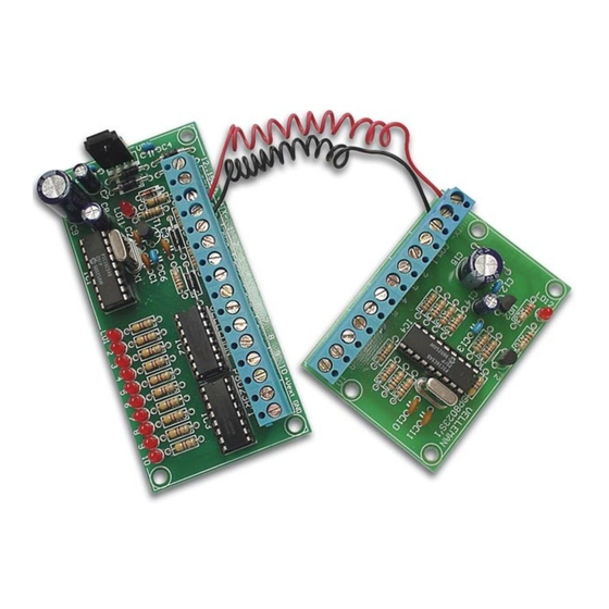
- Page 1 Total solder points: 247 Difficulty level: beginner 1 advanced 10 Channel, 2-Wire REMOTE CONTROL K8023 ILLUSTRATED ASSEMBLY MANUAL H8023IP-1...
- Page 2 Features & Specifications Features: Microprocessor controlled. Inputs can be push-buttons, switches or open collector outputs from another device. The receiver section provide 10 open collector outputs which allow you to control relays directly. Terminal block connectors for all input and output connections are included. All outputs are provided with LED indication.
- Page 3 Assembly hints 1. Assembly (Skipping this can lead to troubles ! ) Ok, so we have your attention. These hints will help you to make this project successful. Read them carefully. 1.1 Make sure you have the right tools: • A good quality soldering iron (25-40W) with a small tip.
- Page 4 REMOVE THEM FROM THE TAPE ONE AT A TIME ! AXIAL COMPONENTS ARE TAPED IN THE COR- RECT MOUNTING SEQUENCE ! You will find the colour code for the resistances and the LEDs in the HALG (general manual) and on our website: http://www.velleman.be/common/service.aspx...
- Page 5 Construction Assembly of the receiver PCB : P8023R 1. Diodes. Watch the polarity! 3. Resistors 4. IC sockets, Watch the position of the notch! D1 : 1N4007 D... CATHODE R... D2 : 1N4007 IC1 : 18p D3 : 1N4007 IC2 : 16p D4 : 1N4007 IC3 : 16p D5 : 1N4007...
- Page 6 Construction 6. LEDs. Watch the polarity ! 8. Electrolytic capacitors. 11. Electrolytic capacitor. Watch the polarity ! Watch the polarity ! COLOR= 2...5 C7 : 10µF C9 : 1000µF /25V LD... C... C... C8 : 100µF CATHODE 3mm RED 12. Voltage regulator 9.
- Page 7 Construction Assembly of the receiver PCB : P8023S R25 : 10K (1 - 0 - 3 - B) 1. Diode. Watch the polarity! 5. LED. Watch the polarity ! R26 : 10K (1 - 0 - 3 - B) R27 : 10K (1 - 0 - 3 - B) COLOR= 2...5 R28 : 220 (2 - 2 - 1 - B - 9) D7 : 1N4007...
- Page 8 Construction 8. Electrolytic capacitor. 11. Electrolytic capacitor. Watch the polarity ! Watch the polarity ! C14 : 10µF C ... C15 : 470µF /25V C... 9. Quartz crystal 12. IC mounting X2 : 4MHz X... IC4 : VK8023 PIN 1 VK8023=(Programmed PIC16C54C-04) 10.
- Page 9 Hook-up & testing 13. Hook - up & Testing Connect both PCB’s P8023S and P8023R according to fig.1. P8023S Both push buttons and switches can be used to control the inputs. Keep the distance between the switches or push buttons and the circuit as short as possible. If the circuit is used in a noisy environment (e.g.
- Page 10 Operation 14. Operation 1. Control section (P8023S): Both PCBs are connected to each other by means of two wires, VTX+ and VTX-. They supply power to the control board and carry the data signal. This signal contains information regarding the status of the 10 inputs. Filtering and regulating of the power supply is performed by VR2, together with C15, C12, C13 and C14, which also suppress possible oscillation of the voltage regulator.
-
Page 11: Hook-Up Examples
Hook-up examples 15. Hook-up Examples 1. Connecting the K8023 to the K6714, relais card. P6714 VB GND 1 12 13 14 15 From P8023S 12..15Vin +VTX- 10 +Vext GND P8023R... - Page 12 Hook-up examples 2. Connecting the K8023 to the K6711, IR receiver. P8023S +VTX- COM 1 TO P8023R VA GND VB GND 1 11 12 13 14 15 P6711...
- Page 13 Hook-up examples 3. Connecting the K8023 to the K8006, modular light system. P8006 Base unit for home modular light system From P8023S TO SECOND K8006 12V/300mA 12..15Vin +VTX- 10 +Vext GND P8023R...
- Page 14 Hook-up examples 4. Connecting the K8023 to the K8000, computer interface card. P8000 Computer Interface Board From P8023S +12VDC 12..15Vin +VTX- 10 +Vext GND P8023R...
-
Page 15: Schematic Diagram - Control Section
Schematic diagram 16. Schematic diagram (Control section) UA78L05 Vout 1N4007 100n 100n 10µ 470µ/25-35V GND2 GND2 GND2 GND2 GND2 GND2 LD12 LED3RL OSC1/CLKIN OSC2/CLKOUT T0CKI 4MHz MCLR/VPP GND2 220/0.6W GND2 GND2 VK8023 (PIC16C54) BC547 GND2 GND2 SK10 SK11 SK12 SK13 SK14... - Page 16 Schematic diagram 17. Schematic diagram (Receiver section) UA7810 12...15Vin 1N4007 Vout 56/0.6W 1N4007 1N4007 100n 1N4007 100n 10µ 100µ 1000µ/25V LED3RL LD11 1N4007 BC547 330p 1N4007 OSC1/CLKIN OSC2/CLKOUT IN 1 OUT 1 T0CKI IN 2 OUT 2 4Mhz MCLR/VPP IN 3 OUT 3 IN 4 OUT 4...
- Page 17 18. Control PCB VELLEMAN P8023S'1 +VTX- SK12 SK13 SK14 SK10 SK11...
- Page 18 19. Receiver PCB 12..15Vin +VTX- +Vext VELLEMAN P8023R'1 T1 C3 LD11...
- Page 20 VELLEMAN Components NV Legen Heirweg 33 9890 Gavere Belgium Europe www.velleman.be www.velleman-kit.com Modifications and typographical errors reserved © Velleman Components nv. H8023IP - 2004 - ED1 5 4 1 0 3 2 9 2 9 0 8 1 8...
Need help?
Do you have a question about the High-Q Velleman-kit K8023 and is the answer not in the manual?
Questions and answers