
Subscribe to Our Youtube Channel
Related Manuals for Velleman K6501


Summary of Contents for Velleman K6501
- Page 1 Total solder points: 338 Difficulty level: beginner 1 advanced Remote control by telephone K6501 ILLUSTRATED ASSEMBLY MANUAL H6501IP-1...
- Page 2 Features & Specifications Features: Controlled from a touch tone phone (DTMF). Unit gives audible feedback of output status. Adjustable security code. Pickup after 4 or 7 rings possible. Room for three output relays, one relay included. Input to monitor the status of a switch from a distance. Specifications: •...
- Page 3 Assembly hints 1. Assembly (Skipping this can lead to troubles ! ) Ok, so we have your attention. These hints will help you to make this project successful. Read them carefully. 1.1 Make sure you have the right tools: • A good quality soldering iron (25-40W) with a small tip.
- Page 4 REMOVE THEM FROM THE TAPE ONE AT A TIME ! AXIAL COMPONENTS ARE TAPED IN THE COR- RECT MOUNTING SEQUENCE ! You will find the colour code for the resistances and the LEDs in the HALG (general manual) and on our website: http://www.velleman.be/common/service.aspx...
- Page 5 Construction 1.Jumpers 3. Zenerdiodes. Watch the : 4K7 (4 - 7 - 2 - B) : 4K7 (4 - 7 - 2 - B) polarity! J : 5x R10 : 4K7 (4 - 7 - 2 - B) R11 : 4K7 (4 - 7 - 2 - B) R12 : 4K7 (4 - 7 - 2 - B) ZD...
- Page 6 Construction Resistors 7. Capacitors 9. LEDs. Watch the polarity ! 1/2W COLOR= 2...5 R... LD... LD... CATHODE C1 : 4n7 (472) CATHODE C2 : 22nF (223) R33 : 22 (2 - 2 - 0 - B - 9) R34 : 22 (2 - 2 - 0 - B - 9) C3 : 33nF (333) C4 : 100nF (104)
-
Page 7: Screw Connectors
Construction 10. Push button 13. VDR 16. Screw connectors VDR1 SW1 : 1 pos. 14. Electrolytic capacitors. J1 : 2p Watch the polarity ! J2 : 2p 11. Transistors J3 : 2p C10 : 1µF J4 : 2p C11 : 1µF C... -
Page 8: Voltage Regulator
Construction 18. Electrolytic capacitor. 21. Relays Watch the polarity ! C16 : 470µF C ... RY... RY... RY1 : VR10V121C (1p/12VDC) 19. Capacitor RY2 : VR10V121C (1p/12VDC) 22. IC mounting IC1 : 4N35 IC2 : HT9170 C17 : 0.47µF / 250V IC3 : VK6501 PIN 1 20. -
Page 9: Manual Operation
Connection & manual operation 23. Connection TEL. LINE 12VAC/300mA 1. Connect the telephone connections ‘A’ and ‘B’ to the telephone line connections ‘a’ and ‘b’. 2. Connect a transformer or adapter of 12VAC min. 300mA to the AC connections. TEL. LINE 3. -
Page 10: Setting The Code
Code setting 25. Setting the code See table to set the first digit (CODE1 or decades) and the second digit (CODE2 or units). D C B A CODE1 CODE2... -
Page 11: Setting The Number Of Rings
Setting the numbers of rings 26. Setting the number of rings Normally the device is set to pick up the phone after ± 8 rings. If, however, you would like the device to pick up the phone sooner (after ± 3 rings), the manual operating push button should be held pressed before switching on the power supply. - Page 12 27. Use ESTABLISHING THE CONNECTION: Call the phone number to which the remote control is connected. After about 3 or 8 rings the remote control will answer. The red "ON LINE" LED on the device will flash. A few seconds after picking up you will hear the condition of the outputs. First de switch input, then output 1, output 2, and output 3 in that order.
- Page 13 Enclosure 28. Mounting into a housing (Optional) The entire circuit may be built into a plastic housing (e.g. our housing type D30), which will allow the LEDs and the push button to protrude through the front panel (see figure for boreholes and board position). After cutting out the LED frame, the included sticker may be attached to the front panel.
- Page 14 Schematic diagram 29. Schematic diagram.
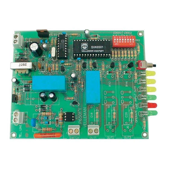
- Page 15 30. PCB...
- Page 16 Modifications and typographical errors reserved VELLEMAN NV © Velleman nv. Legen Heirweg 33, 9890 Gavere H6501IP - 2004 - ED1_rev.2 Belgium - Europe 5 4 1 0 3 2 9 2 8 9 4 3 0...
Need help?
Do you have a question about the K6501 and is the answer not in the manual?
Questions and answers