Advertisement
Quick Links
Total solder points: 66
Difficulty level:
beginner 1 o 2 o 3 þ 4 o 5 o advanced
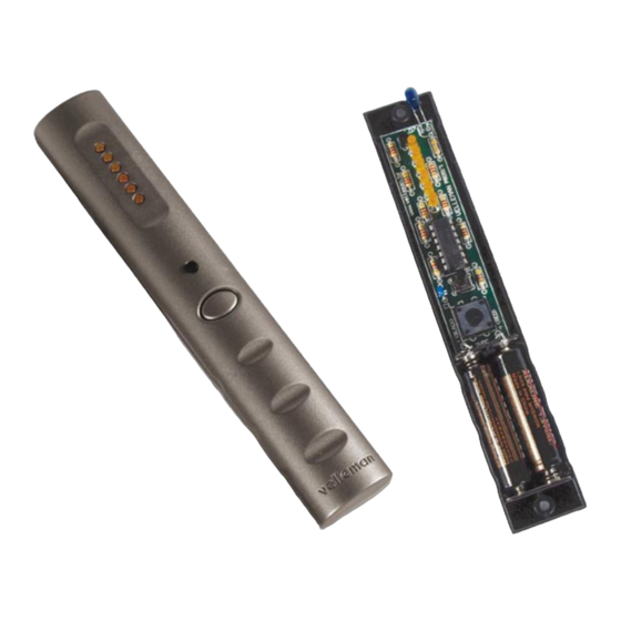
15 Channel IR remote stick
Features:
þ Slim designer enclosure.
þ 2-button operation.
þ Built-in 'all clear' function
þ 3 addresses with 15 channels each.
þ Easy channel and address selection.
þ Compatible with most current and upcoming IR kits.
þ Low power consumption.
Specifications:
• Power supply : 2 x AAA battery (not included).
• Dimensions : 160x27x23mm / 6,3x1x0,9"
• Range : up to 20m (K8050 / indoors)
ILLUSTRATED ASSEMBLY MANUAL
K8051
H8051IP-1
Advertisement

Related Manuals for Velleman K8051


Summary of Contents for Velleman K8051
- Page 1 Total solder points: 66 Difficulty level: beginner 1 o 2 o 3 þ 4 o 5 o advanced 15 Channel IR remote stick K8051 Features: þ Slim designer enclosure. þ 2-button operation. þ Built-in ‘all clear’ function þ 3 addresses with 15 channels each.
- Page 2 VELLEMAN Components NV Legen Heirweg 33 9890 Gavere Belgium Europe www.velleman.be www.velleman-kit.com...
- Page 3 Assembly hints 1. Assembly (Skipping this can lead to troubles ! ) Ok, so we have your attention. These hints will help you to make this project success- ful. Read them carefully. 1.1 Make sure you have the right tools: •...
- Page 4 Assembly hints 1.3 Soldering Hints : Mount the component against the PCB surface and carefully solder the leads Make sure the solder joints are cone-shaped and shiny Trim excess leads as close as possible to the solder joint AXIAL COMPONENTS ARE TAPED IN THE CORRECT MOUNTING SEQUENCE ! REMOVE THEM FROM THE TAPE ONE AT A TIME !
- Page 6 Construction 1. Resistors 4. IC socket. Watch the position of the notch! R... q R1 : 4E7 (4-7-B-B) q R2 : 330 (3-3-1-B) : 330 (3-3-1-B) q IC1 : 14p q R4 : 330 (3-3-1-B) q R5 : 330 (3-3-1-B) 5.
- Page 7 Construction 7. Mounting the LED readout 1. Stick a piece of tape over the LED mounting holes. This allows you to level the LEDs before soldering them.(see fig. 1.0). FIG 1.0 Complete the assembly as follows : 2. Insert the LEDs BUT DO NOT SOLDER THEM YET! Mind the polarity ! (fig 2.0) CATHODE q LD1...
- Page 8 Construction 3. Flip the PCB and guide all LEDs trough their holes (fig 3.0). => Make sure that all LEDs touch the tape! FIG 3.0 4. Solder the connections (fig 4.0). 5. Remove the tape. FIG 4.0...
- Page 9 Enclosure preparation 8. Enclosure preparation 2 Holes must be drilled into the enclosure. Follow next steps exactly! Pay attention to the correct diameter. Make sure the holes are free of burrs. STEP 1 Drawing 5.0 provides a drill pattern for the ‘select’ button. •...
- Page 10 Enclosure preparation STEP 2 Drawing 7.0 provides a drill pattern for the IR-LED. • Close the enclosure with the 2 supplied screws. Mark the centre of the hole to be drilled on the top of the enclosure (Fig 6.0). Make sure that the centre of the hole is in the middle of the housing and 7mm from the left hand side (Fig 7.0) LEDs...
- Page 11 Mounting the PCB 9. Mounting the PCB STEP 1 Mount the ‘select’ push button. (SW2) STEP 2 Mount the infrared LED (mounting height: 20mm) (fig 8.0). FIG 8.0 LD7 : L-53F3BT (blue) CATHODE 20mm...
- Page 12 Mounting the PCB STEP 3 Solder two jumperwires ( - & +). Jumpers STEP 4 Place the battery contacts. Pay attention to the polarity ! (Fig 10) FIG 9.0...
- Page 13 Mounting the PCB STEP 5 Place the PCB into the housing. STEP 6 Bend the IR LED so that it fits the hole you’ve drilled be- fore (Fig10). FIG 10...
- Page 14 Mounting the PCB STEP 7 Solder the jumperwires to the matching battery connector. STEP 8 Before continuing, inspect your complete assembly once more ! FIG 11 Place two AAA-batteries in their support. (Fig 11). If the batteries have been inserted correctly and no assem- bly mistakes have been made, the LEDs will show a brief animation, hereby indicating that the unit is ready for use.
- Page 15 Final assembly 10. Final assembly Now you can close the enclosure using the two supplied screws. Do not forget the pushbutton ! (Fig. 12). FIG 12...
- Page 16 Operation 11. Operation IR LED 6-LED-readout ‘Select’-button ‘Transmit’-button To operate a channel : Press the ‘Transmit’- button. The LED-readout will flash a # of LEDs in a bar-style accor- ding to the selected channel as long as the button is pres- sed.
- Page 17 : 3mm red To change the address : q LD4 : 3mm red Some Velleman IR kits feature address selection (such as q LD5 : 3mm red the K8050 15 channel receiver), to increase the # of availa- q LD6...
- Page 18 12. PCB layout.
- Page 19 Diagram 13. Diagram...
- Page 20 Modifications and typographical errors reserved © Velleman Components nv. H8051IP - 2003 - ED1...
Need help?
Do you have a question about the K8051 and is the answer not in the manual?
Questions and answers