
Subscribe to Our Youtube Channel
Related Manuals for ECOWITT WH0281A


Summary of Contents for ECOWITT WH0281A
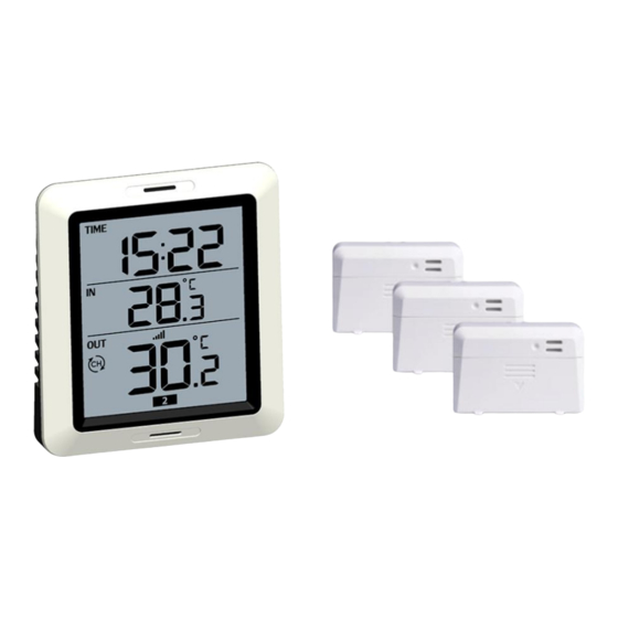
- Page 1 Instruction Manual Wireless Indoor Outdoor Thermometer With 3 Remote Temperature Sensors...
-
Page 2: Table Of Contents
Instruction Manual Table of Contents 1. Introduction.............4 2. Get Started............4 2.1 Parts List..........5 2.2 Recommend Tools........5 2.3 Thermometer Sensor Set Up....5 2.4 Display Console Set Up......7 2.4.1 Display Console Layout....10 2.4.2 Sensor Operation Verification..11 3. Wireless Sensor Installation......11 3.1 Mounting with Zip Tie......11 3.2 Mounting with Nail or Screw....12 4. - Page 3 Instruction Manual 4.2 Setting for Alarm Clock......15 4.3 Setting for Min/Max Record....15 4.4 Setting for RF Channels......17 5.Sensor Resynchronization....... 18 6.Best Practices for Wireless Communication..18 7.Specifications............19 7.1 Wireless Specifications....... 19 7.2 Measurement Specifications....20 7.3 Power Consumption......20 8. Warranty Information........21...
-
Page 4: Introduction
Instruction Manual 1. Introduction Thanks for your purchasing of the Wireless Indoor Outdoor Thermometer with 3 Remote Temperature Sensors. To ensure the best product performance, please read this manual and retain it for future reference. 2. Get Started Note: Power up sequence must be performed in the order shown in this section (insert batteries in the Remote Sensor first, Display Console second). -
Page 5: Parts List
Instruction Manual regard to polarity +/- 2.1 Parts List One Display Console (Receiver) Three remote sensors (Transmitter) One User Manual 2.2 Recommend Tools Hammer hanging remote thermometer transmitter. 2.3 Thermometer Sensor Set Up Remove the battery door on the back of one sensor by sliding the compartment door down, as shown in Figure 1. - Page 6 Instruction Manual Set RF sensor channel. Figure 1 Wireless transmitter LED 1, 2, 3 RF Channels AA Battery Compartment Battery Compartment Cover Note: This device supports up to 3 sensors, to set each channel number, change Dip Switches 1, 2, 3 as referenced in Figure 1.
-
Page 7: Display Console Set Up
Instruction Manual Insert one AA battery. After inserting the battery, the remote sensor LED indicator will light for 4 seconds, and then flash once per 60 seconds thereafter. Each time flashes, sensor transmitting data. Close the battery door. Repeat for the additional remote sensor, verifying each remote is on a different channel. - Page 8 Instruction Manual battery in the back of the display console. Figure 2 1. Integrated Hang Hole 2. Stand Mount 3. CH/+ Button 4. Mode Button 5. Battery Compartment 6. Battery Compartment Cover...
- Page 9 Instruction Manual All of the LCD segments will light up for a few seconds to verify all segments are operating properly. Replace the battery door, and fold out the desk stand and place the console in the upright position. The console will instantly display indoor temperature.
-
Page 10: Display Console Layout
Instruction Manual 2.4.1 Display Console Layout Figure 3 1. Alarm Clock Icon 2. Current Indoor Temperature 3. RF Channels 4. Time 5. Outdoor Reception Icon 6. Current Outdoor Temperature... -
Page 11: Sensor Operation Verification
Instruction Manual 2.4.2 Sensor Operation Verification Verify the indoor and outdoor temperature match closely with the console and sensor array in the same location (about 2 to 3m apart). The sensors should be within 2°F (the accuracy is ± 1°F). Allow about 30 minutes for both sensors to stabilize. -
Page 12: Mounting With Nail Or Screw
Instruction Manual better accuracy when mounting outside, since it is not touching another object. Other objects will store and radiate heat (or cold). Figure 4 3.2 Mounting with Nail or Screw To mount the sensor with a nail or screw, the cap must be less than or equal to 5.0 mm in diameter. -
Page 13: Console Operation
Instruction Manual Figure 5 4. Console Operation Note: The console has two buttons for easy operation: 【 CH/+ 】 button (on the left), and 【MODE】button (on the right). If no operation for 30s, display will return to normal mode. -
Page 14: Setting For 12/24Hr Switch, Time And °C/°F Switch
Instruction Manual 4.1 Setting for 12/24hr Switch, Time and °C/°F Switch Long press【MODE】button 2s, step into setting mode. a. Short press【CH/+】 switch 24/12hr display b. Short press【MODE】,step into Hour setting, Short press【 CH/+ 】to adjust the number from 1-12 or 0-23. c. -
Page 15: Setting For Alarm Clock
Instruction Manual 4.2 Setting for Alarm Clock Short press 【 MODE 】 button, step into alarm clock display setting mode, short press 【CH/+】 to enable ( speaker icon is lit) or disable alarm function. a. Long press 【MODE】 button 3s, step into alarm Hour setting, Short press【... - Page 16 Instruction Manual value display mode. b. Short press【CH/+】to select other available outdoor sensor Min value (if no extra outdoor sensor available, it will display “--.-“ instead). c. Long press 【CH/+】 2s, reset the Min value of indoor temperature and the current displayed Min value of outdoor RF channel.
-
Page 17: Setting For Rf Channels
Instruction Manual indoor temperature and the current displayed Max value of outdoor RF channel. 4.4 Setting for RF Channels During normal display mode, press 【CH/+】to select outdoor sensor display in the following sequence: CH1 – CH2 – CH3 – Note: When the icon appears, it means the station enters cycle display mode and it will display temperature readings of the three... -
Page 18: Sensor Resynchronization
Instruction Manual 5.Sensor Resynchronization when the remote sensor lost reception or extra sensors to be added, press both the 【CH/+】 and 【MODE】 buttons at the same time for five seconds. While in the search mode, the reception search icon flash. 6.Best Practices for Wireless Communication Note: To insure proper communication, mount... -
Page 19: Specifications
Instruction Manual 7.Specifications 7.1 Wireless Specifications Line of sight wireless transmission (in open air): 300feet(100meters) Frequency: 433 MHz Update Rate: 60 seconds... -
Page 20: Measurement Specifications
Instruction Manual 7.2 Measurement Specifications The following table provides specifications for the measured parameters. Measurement Range Accuracy Resolution Indoor 14 to 140 °F ± 1 °F/°C 0.1 °F/°C Temperature /-10 to 60℃ Outdoor -40 to 140 °F ± 1 °F/°C 0.1°F/°C Temperature /-40 to 60℃... -
Page 21: Warranty Information
Instruction Manual 8. Warranty Information We disclaim any responsibility for any technical error or printing error, or their consequences. All trademarks and patents are recognized. We provide a 1-year limited warranty on this product against manufacturing defects in materials and workmanship. This limited warranty begins on the original date of purchase, is valid only on products purchased and only to the original purchaser of this product. - Page 22 Instruction Manual the product itself, and does not cover the cost of installation or removal from a fixed installation, normal set-up or adjustments, claims based on misrepresentation by the seller or performance variations resulting from installation-related circumstances.
Need help?
Do you have a question about the WH0281A and is the answer not in the manual?
Questions and answers