Table of Contents
Advertisement
Advertisement
Table of Contents

Related Manuals for Pregis AirSpeed SMART V3


Summary of Contents for Pregis AirSpeed SMART V3
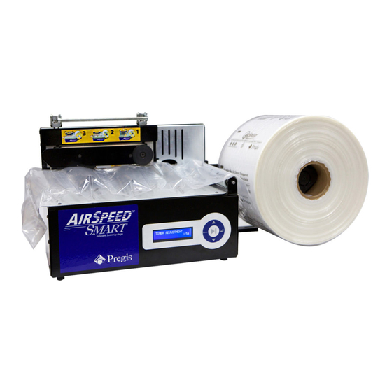
- Page 1 Air Cushion Technology AirSpeed™ SMART Technical Manual...
- Page 2 Revision History Date Description 04/15/13 Original 05/02/13 Added detail in Section 4.2 on Bin Sensors 07/22/13 Updated advanced menu to match version 2 software...
-
Page 3: Table Of Contents
TABLE OF CONTENTS SECTION 1 – Overview .................... 1 Introduction....................1 Sensors ......................1 1.2.1 Jaw Sensor ....................1 1.2.2 Lost Film Sensor ..................2 SECTION 2 – Operation .................... 3 General Operation Screen................. 3 2.1.1 Special operation for a run length of 0:00 ............ 3 Setting Screens .................... - Page 4 5.3.3 Initial Change from Idle to Run ..............14 5.3.4 Stopping Unit ..................14 5.3.5 Sample Display – Idle ................14 5.3.6 Sample Display – Run ................15 Selecting between „Operational‟ and „Burn-in‟ Modes .......... 15 SECTION 6 – Loading New Software ................ 16 Introduction....................
-
Page 5: Overview
SECTION 1 – OVERVIEW 1.1 Introduction This document describes how to operate the new Pregis AirSpeed™ SMART unit, commonly referred to as Version 3. The document is written for Pregis Systems field technicians, therefore, familiarity with the original SMART unit is assumed. -
Page 6: Lost Film Sensor
1.2.2 Lost Film Sensor The lost film sensor monitors the rotation of the film roller. If the rotation stops for more than three seconds, film is assumed to have been exhausted or jammed; the unit immediately stops. The lost film sensor can be ignored by setting „test mode‟... -
Page 7: Operation
SECTION 2 – OPERATION 2.1 General Operation Screen TIMER ADJUSTMENT The unit powers on with the last setting for run 3:00 length displayed. length time (minutes:seconds) where the arrow keys are used to increase or decrease Pressing Play starts the unit. While running, the timer counts down to 0:00 then stops. -
Page 8: Temperature Setting Screen
2.2.1 Temperature Setting Screen The Temperature Setting screen is available only TEMPERATURE after the entry of a valid password, see section 3.1 . While in the General Operation screen, pressing the Menu button brings you to the Temperature Setting screen Use the arrow keys to increase or decrease the temperature of the seal wire. -
Page 9: Inflation Setting Timeout
Temperature Setting screen, brings you to the Inflation Setting screen. Use the arrow keys to increase or decrease the air inflation setting. The value is a percentage of the allowed inflation range that is set on the Advanced Setup screen. The Inflation Setting screen can be entered while the unit is running and any changes take effect immediately. -
Page 10: Advanced Setup
SECTION 3 – ADVANCED SETUP Advanced setup is available to factory or field personnel by entering a password. 3.1 Password Screen While in the General Operation screen and while the PASSWORD unit is not running, you can bring up the password screen which, in turn, allows entry to the advanced setup. - Page 11 through the parameters using the arrow keys. Pressing the down arrow scrolls to the next parameter in the list. Some parameters you can change; others are view only. When a changeable parameter is at the top of the screen, it is identified by an underline immediately to the right of its value. Figure 2 shows example.
-
Page 12: Exiting Advanced Setup
3.2.1 Exiting Advanced Setup Pressing the Menu key returns you to the General Operation screen. Pressing the Play key starts the unit and returns you to the General Operation screen. If you don‟t press a key for 60 seconds, the Advanced Setup screen times- out and the unit returns to the General Operation screen. -
Page 13: Air Low & Air High
3.2.2.5 Air Low & Air High These parameters form the range in which an operator can set the inflation value, see section 2.2.2 . Both values are expressed as a percentage of the blowers speed; from „full off‟ (0) to „full on‟ (100). Air Low can be set from zero to Air High minus one. -
Page 14: Bin Sensor
3.2.2.9 Bin Sensor This parameter selects the bin sensor. Set this parameter to OFF if no sensor is present, IR if the infrared sensor is present and US if the Ultra Sonic Bin sensor is present. See section 4.2 for a detailed explanation of the bin sensors. -
Page 15: Optional Accessories
SECTION 4 – OPTIONAL ACCESSORIES 4.1 Foot Pedal The foot pedal operates the same as the play button. When the Time Adjustment is set to 0:00 - pressing the foot pedal once starts the unit, pressing a second time stops the unit. If the Time Adjustment is something other than 0:00 then pressing the foot pedal will start the unit;... -
Page 16: Ultasonic Sensor
Please read the Training document on the Pregis Tech Portal. The sensor is designed to turn ON when there is material present and OFF when there is no material. Position the Ultrasonic sensor over the material. Follow the instructions in Section 3 for selecting the US sensor. -
Page 17: Unit Burn In
SECTION 5 – UNIT BURN IN 5.1 Introduction At unit power-up the controlling software interrogates a jumper on the processor card. If the jumper is not installed the unit enters its „operational‟ state. If the jumper is installed the unit enters its „burn-in‟ state. 5.2 Operational State The unit‟s „operational‟... -
Page 18: Selecting Between Bin Sensors
5.3.2 Selecting between Bin Sensors Once the unit has entered burn-in mode the jumper (JP2) is reassigned to be a „bin sensor select‟. If the jumper is installed the burn-in software looks for the Infrared sensor. If the jumper is not installed the burn-in software looks for the Ultrasonic sensor. -
Page 19: Sample Display - Run
5.3.6 Sample Display – Run Figure 7 A sample „run‟ display is shown in . The display shows the sealer temperature and the time remaining in the „run‟ state SEALER TEMP: 215.5 RUN STATE 420 Figure 7 Sample Running Display 5.4 Selecting between „Operational‟... -
Page 20: Loading New Software
SECTION 6 – LOADING NEW SOFTWARE 6.1 Introduction At power-on the AirSpeed™ Smart‟s Bootloader executes. This bootloader is used to update the unit‟s application software. If the bootloader does not detect new software, the existing application software is started. 6.2 Procedure The new software is stored on a USB memory stick.
Need help?
Do you have a question about the AirSpeed SMART V3 and is the answer not in the manual?
Questions and answers