Advertisement
Available languages
Available languages
Quick Links
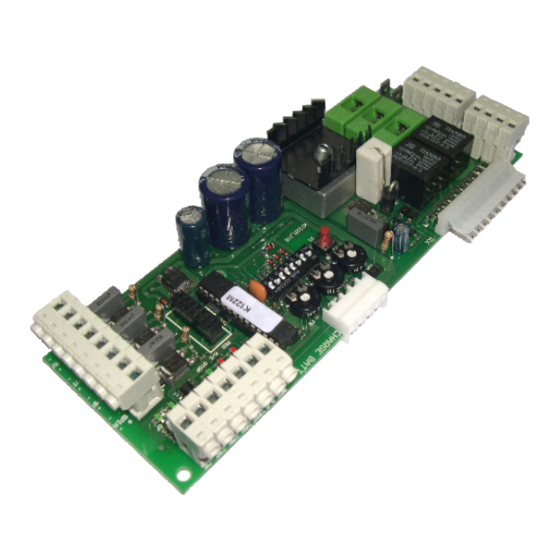
K122M
QUADRO DI COMANDO PER MOTORIDUTTORE SPEED 2
CONTROL PANEL FOR SPEED 2 GEARMOTOR
SCHALT- UND STEUERTAFEL FÜR DEN GETRIEBEMOTOR SPEED 2
LOGIQUE DE COMMANDE POUR MOTORÉDUCTEUR SPEED 2
PANEL DE MANDOS PARA MOTORREDUCTOR SPEED 2
GUIDA ALL'INSTALLAZIONE
INSTALLATION GUIDE
INSTALLATIONSANLEITUNG
NOTICE D'INSTALLATION
GUÍA PARA LA INSTALACIÓN
TAU
srl
via E. Fermi, 43 - 36066 Sandrigo (VI) Italia - Tel ++390444750190 - Fax ++390444750376 - E-mail: info@tauitalia.com
TAU
Edizione 02 - anno 2005
http://www.tauitalia.com
rev. 04 del 28/07/2005
K122M
1
Srl
Advertisement

Related Manuals for tau K122M


Summary of Contents for tau K122M
- Page 1 K122M QUADRO DI COMANDO PER MOTORIDUTTORE SPEED 2 CONTROL PANEL FOR SPEED 2 GEARMOTOR SCHALT- UND STEUERTAFEL FÜR DEN GETRIEBEMOTOR SPEED 2 LOGIQUE DE COMMANDE POUR MOTORÉDUCTEUR SPEED 2 PANEL DE MANDOS PARA MOTORREDUCTOR SPEED 2 GUIDA ALL’INSTALLAZIONE INSTALLATION GUIDE INSTALLATIONSANLEITUNG NOTICE D’INSTALLATION...
- Page 2 This manual is designed to assist qualifi ed installation personnel only. It contains no information that may be of interest to fi nal users. This manual is attached to the K122M control unit mounted on the Speed 2 gearmotor, therefore it may not be used for different products! Important warnings: Disconnect the mains power supply to the board before accessing it.
- Page 3 Das vorliegende Handbuch ist nur für technisches, zur Installation qualifi ziertes Personal bestimmt. Die im vorliegenden Heft enthaltenen Informationen sind für den Endbenutzer nicht interessant. Diese Anleitung liegt der Steuerung K122M bei, die an den Getriebemotor Speed 2 montiert ist, und darf daher nicht für andere Produkte verwendet werden! Wichtige Hinweise: Vor Eingriffen an der Steuerkarte die Netzstromversorgung abtrennen.
- Page 4 El presente manual está destinado sólo al personal técnico cualifi cado para la instalación. Las informaciones que contiene este fascículo no pueden considerarse de interés para el usuario fi nal. Este manual se adjunta a la centralina K122M montada en el motorreductor Speed 2 y, por lo tanto, no debe utilizarse para productos diversos.
- Page 5 Cuando proyecta sus propios equipos, TAU respeta las normativas aplicables al producto (véase la declaración de conformidad adjunta); es fundamental que el instalador, cuando lleva a cabo las instalaciones, respete también de forma escrupulosa las normas.
- Page 6 Antenna Fotocellula 1 1 1 1 1 1 0 0 Spia cancello Lamp 18Vdc aperto max max 20W Positivo + Segnale Negativo - K122M...
- Page 7 FRANÇAIS Pag. 32 ESPAÑOL Pag. 38 SCHEMA CABLAGGIO K122M / K122M WIRING DIAGRAM / SCHALTPLAN DER K122M / SCHÉMA CÂBLAGE K122M / ESQUEMA DEL CABLEADO K122M Pag. 40 SCHEDA BATTERIA (OPZIONALE) / BATTERY CHARGER BOARD (OPTIONAL) / BATTERIELADEKARTE (OPTIONAL) / CARTE CHARGEUR DE BATTERIE (EN OPTION) / TARJETA CARGA BATERÍA (OPCIONAL)
- Page 8 Fusibile rapido protezione ausiliari 18 V dc (F3 - 5x20) F 1,6A Tensione circuiti alimentazione motore 18 Vdc Tensione alimentazione circuiti dispositivi ausiliari 18 Vdc Tensioni alimentazioni circuiti logici 5 Vdc Temperatura di funzionamento -20 °C ÷ +70 °C K122M...
- Page 9 PROCEDURA DI MEMORIZZAZIONE ATTENZIONE: Dopo aver alimentato il quadro di comando attendere 2 sec. prima di iniziare a svolgere le manovre di regolazione. N.B. Il cancello deve necessariamente avere i necessari fermi di sicurezza sia in apertura che in chiusura. K122M...
- Page 10 “verifi ca delle fotocellule” è disinserita. N.B.: da utilizzare quando non si usano le fotocellule; 7 on: in seguito all’intervento del contatto fotocellula (ingresso 10 - 11), l’automazione si chiude automaticamente dopo 5 secondi; off: funzione disinserita; K122M...
- Page 11 Dip-switches CARATTERISTICHE DELLA K122M LED - DL3 Il led, oltre ad indicare la presenza dell’alimentazione, segnala eventuali errori con una serie di lampeggi predefi niti: •...
- Page 12 Nel caso la tensione scenda sotto gli 11,3 Vdc, l’automazione cessa di funzionare (il quadro di comando rimane alimentato); quando, invece, scende sotto i 10,2 Vdc, la scheda sgancia completamente la batteria (il quadro di comando non è più alimentato). K122M...
- Page 13 Non installare l’antenna in posizioni basse o in posizioni nascoste dalla muratura o dal pilastro; e- Controllare lo stato delle pile del radiocomando. 3- L’automazione si apre al contrario Invertire tra loro i collegamenti del motore sulla morsettiera (morsetti 20 e 21); K122M...
- Page 14 Fast acting fuse for protection of auxiliary circuits 18 V dc (F3 - 5x20) F 1,6A Motor power supply circuits voltage 18 Vdc Auxiliary device circuits supply voltage 18 Vdc Logic circuits supply voltages 5 Vdc Operating temperature -20 °C ÷ +70 °C K122M...
- Page 15 13.5 Vac – Powered by the toroidal transformer housed in the SPEED 2 motor and protected by a fuse on the 230 Vac power supply ; MEMORIZATION PROCEDURE WARNING: After powering the control panel, wait 2 seconds before you start performing the adjustment operations. K122M...
- Page 16 6 on: the “photocell test” function is enabled; off: the “photocell test” function is disabled. N.B.: to be used when the photocells are not used; 7 on: following the connection of the photocell contact (input 10 - 11), the gate closes automatically after 5 seconds; K122M...
- Page 17 Clock function: A timer can be connected to the open-close pushbutton in order to keep the gate open at certain times during the day, after which it reverts to automatic closing. K122M CHARACTERISTICS Dip-switches LED - DL3 The LED, besides indicating that the power supply is connected, also signals errors with a series of pre-defi...
- Page 18 If the system is equipped with a battery charger board, it con operate even during power failures. If the voltage drops below 11.3 Vdc, the automation stops working (the control panel is still powered). When it drops below 10.2 Vdc, the board disconnects the battery completely (the control panel is no longer powered). OBSTACLE DETECTION K122M...
- Page 19 Do not install the aerial in a low position or behind walls or pillars; e- Check the state of the radio control batteries. 3- The gate opens the wrong way Invert the motor connections on the terminal block (terminals 20 and 21); K122M...
- Page 20 Schnellsicherung zum Schutz der Hilfskreise 18 V dc (F3 - 5x20) F 1,6A Spannung der Versorgungskreise des Motors 18 Vdc Spannung der Versorgungskreise der Hilfsvorrichtungen 18 Vdc Versorgungsspannungen der logischen Kreisläufe 5 Vdc Betriebstemperatur -20 °C ÷ +70 °C K122M...
- Page 21 23 - 24 Ausgang Motorversorgung 18 Vdc max. 50 W; FS1 - FS2 Eingang Steuerkartenversorgung 13,5 Vac – Versorgt durch Ringtransformator, untergebracht in einem speziellen Abteil des Motors SPEED 2 und geschützt durch Sicherung an der 230 Vac Versorgung; K122M...
- Page 22 Hindernis entfernt ist. In der Schließphase wird das Anhalten gefolgt von einer vollständigen Öffnung des Tors verursacht; off: während der Öffnungsphase spricht die Fotozelle nicht an, wogegen sie sich in der Schließung wie im Modus ON verhält; 4 on: das Tor verhält sich, wie vom Dip-Switch Nr. 2 festgelegt; K122M...
- Page 23 Ein Timer kann am Eingang der Taste Öffnet-Schließt angeschlossen werden, so dass das Tor zu bestimmten Tageszeiten geöffnet bleibt und dann automatisch geschlossen wird. Dip-switches MERKMALE DER SCHALT- UND STEUERTAFEL K122M LED - DL3 Diese LED zeigt an, dass die Versorgung vorhanden ist und weist durch eine vorbestimmte Menge an Blinkvorgängen auf eventuelle Defekte hin:...
- Page 24 Blinkleuchte und leuchtet bei Erreichen der vollständigen Öffnung fest weiter. Nach Beendigung der Schließphase wird dieser Leuchtmelder erlöschen. Weiterhin meldet der Leuchtmelder Tor geöffnet folgendes: • Programmierphase (Dip-Switch 8 auf ON); er blinkt synchron zur Blinkleuchte; • Netzspannung wieder vorhanden er blinkt mehrmals für eine Zeit von ca. 2 Sek; K122M...
- Page 25 Die Antenne nicht zu niedrig oder durch Mauern oder Pfeiler versteckt installieren; e- Den Zustand der Batterien in der Funksteuerung überprüfen. 3 – Das Tor öffnet sich umgekehrt Die Anschlüsse des Motors am Klemmenbrett untereinander umkehren (Klemmen 20 und 21); K122M...
- Page 26 F 10A Fusible rapide protection auxiliaires 18 Vcc (F3 – 5x20) F 1,6A Tension circuits d’alimentation moteur 18 Vcc Tension d’alimentation circuits dispositifs auxiliaires 18 Vcc Tension d’alimentation circuits logiques 5 Vcc Température de fonctionnement -20 °C ÷ +70 °C K122M...
- Page 27 18 Vcc max. 50 W ; FS1 - FS2 entrée alimentation carte 13,5 Vca - Alimentée par le transformateur toroïdal situé dans le logement du moteur SPEED 2 et protégé par un fusible sur l’alimentation 230 Vca ; K122M...
- Page 28 ON ; 4 on : le portail se comporte comme l’établit le dip-switch n. 2 ; off : le portail ignore les commandes de fermeture durant l’ouverture ; 5 on : la fonction préclignotement est activée ; K122M...
- Page 29 à certains moments de la journée et en permettre ensuite la refermeture automatique. Dip-switches CARACTÉRISTIQUES DE LA K122M LED - DL3 La led, en plus d’indiquer la présence de tension, signale les éventuelles erreurs avec une série de clignotements prédéfi...
- Page 30 CARTE CHARGEUR DE BATTERIE (EN OPTION) Si l’automatisme est équipé de la carte chargeur de batterie, en l’absence du courant de secteur, il continue à fonctionner quand même. Si la tension descend en dessous de 11,3 Vcc, l’automatisme K122M...
- Page 31 Ne pas installer l’antenne dans des positions basses ou cachées par la maçonnerie ou par le pilier ; e- Contrôler l’état des piles de la radiocommande. 3- Le portail s’ouvre dans le sens contraire Intervertir les connexions du moteur sur le bornier (bornes 20 et 21) ; K122M...
- Page 32 Fusible rápido protección auxiliares 18 V dc (F3 - 5x20) F 1,6A Tensión circuitos alimentación motor 18 Vcc Tensión alimentación circuitos dispositivos auxiliares 18 Vcc Tensiones alimentaciones circuitos lógicos 5 Vcc Temperatura de funcionamiento -20 °C ÷ +70 °C K122M...
- Page 33 18 Vdc máx. 50 W; FS1 - FS2 entrada alimentación tarjeta 13,5 Vac - Alimentado por el transformador toroidal colocado en el correspondiente compartimiento del motor SPEED 2 y protegido por un fusible en la alimentación 230 Vac; K122M...
- Page 34 4 on: la cancela se comporta como establece el dip switch nº. 2 off: la cancela ignora los comandos de cierre durante la apertura; K122M...
- Page 35 Dip-switches CARACTERÍSTICAS DE LA K122M LED - DL3 El led, además de indicar la presencia de la alimentación, señala eventuales errores con una serie de destellos predefi...
- Page 36 (cuando el dip-switch 8 está en ON); emite destellos en sincronía con la luz intermitente; • el restablecimiento de la tensión de red emite una serie de destellos durante un tiempo de aprox. 2 seg.; K122M...
- Page 37 No instale la antena en posiciones bajas o en posiciones escondidas por la pared o por el soporte; e- Controle el estado de las pilas del radiocontrol. 3- La cancela se abre al contrario Invierta entre ellas las conexiones del motor en el terminal de conexiones (bornes 20 y 21); K122M...
- Page 38 SCHEMA CABLAGGIO K122M K122M WIRING DIAGRAM SCHALTPLAN DER K122M SCHÉMA CÂBLAGE K122M ESQUEMA DEL CABLEADO K122M Antenna Dip-switches CONNETTORE RADIO CHARGE BATT. RALL Positivo + 1 2 3 4 5 6 Segnale Negativo - F2 5x20 F10A K122M F3 5x20 F1,6A...
- Page 39 Fotocellula PED A/C STOP C.F. Spia cancello Lamp aperto max 18Vdc K122M...
- Page 40 Fusible rapide 10 Ah 5x20 pour la protection de la batterie 12 V 7,2 Ah led verte de signalisation présence de courant. F 8A - 5x20 Fusible rápido 10 Ah 5x20 como protección de la batería 12 V 7,2 Ah led verde de aviso presencia de alimentación. K122M...
- Page 41 (aux termes de la Directive européenne UE89/392 All. II.A) (según la Directiva Europea UE89/392 Anex. Il.A) Fabbricante / Manufacturer / Hersteller / Fabricant / Fabricante: TAU s.r.l. Indirizzo / Address / Adresse / Adresse / Dirección: Via E. Fermi, 43...
- Page 42 La garantie TAU a une durée de 24 mois à compter de la date d’achat des produits (le document fi scal de vente, ticket de caisse ou facture, fait foi et doit être conservé avec la présente garantie). Le client...
Need help?
Do you have a question about the K122M and is the answer not in the manual?
Questions and answers