Table of Contents
Advertisement
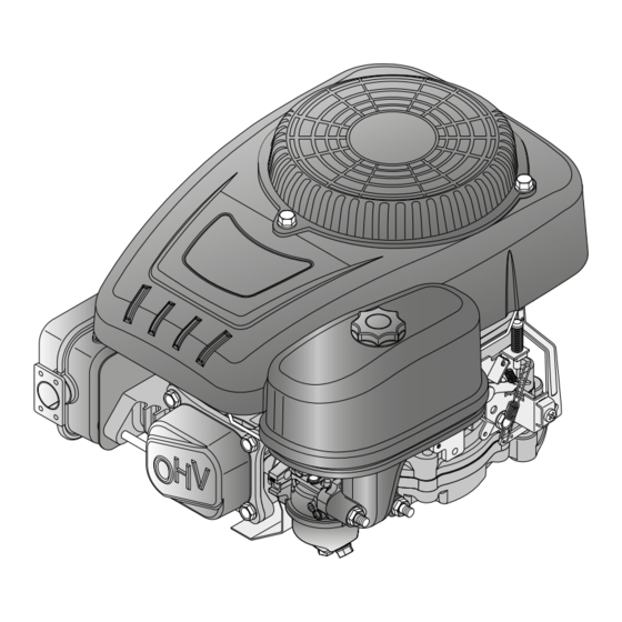
TRE 224
TRE 224
WORKSHOP MANUAL
WORKSHOP MANUAL
2018
Rel. 0.0
PRODUCTION YEAR
The manufacturer reserves the right to make all the necessary technical or commercial improvements to
its products, so there may be some differences between the series of engines and the contents of this
manual. However the basic specifications and different operating procedures will remain the same.
by STIGA - No use of the illustrations or duplication, reproduction or translation, even partial, of the texts
in this document may be made without explicit authorization.
IMPORTANT NOTICE : The information contained herein is intended for Service Operations and professionals
only, able to competently perform the operations described herein, using the appropriate equipment in
order to safeguard se-curity and performance of the machine. The manufacturer is not liable for damages
or injuries arising from operations performed by individuals or inadequate facilities.
Advertisement
Table of Contents

Related Manuals for Stiga TRE 224


Summary of Contents for Stiga TRE 224
- Page 1 However the basic specifications and different operating procedures will remain the same. by STIGA - No use of the illustrations or duplication, reproduction or translation, even partial, of the texts in this document may be made without explicit authorization.
-
Page 3: Table Of Contents
<< BACK >> Engine TRE 224 CONTENTS INTRODUCTION ..................... 5 1. RULES AND PROCEDURES FOR SERVICE CENTRES .......... 6 1.1. Guarantee validity ...........................6 1.2. Service repairs after guarantee period ....................6 1.3. Fault notification ............................6 1.4. Spare parts request ..........................6 2. GENERAL AND SAFETY REGULATIONS ............. 7 2.1. Qualification of operators ........................7... - Page 4 << BACK >> Engine TRE 224 CONTENTS 9. GOVERNOR SYSTEM OF THE CARBURETTOR ..........25 9.1. Adjusting of accelerator cable ......................25 9.2. Adjusting maximum speed ........................26 9.3. Replacing the lever support ........................27 10. AUTO-CHOKE SYSTEM .................. 28 10.1. Replacing of the AUTO-CHOKE system ....................28 11.
-
Page 5: Introduction
Centres the information necessary for a correct particularly important information, risks, warnings maintenance, dismantling and repair procedure and prescriptions: for engines TRE 224. Interventions on the engine must be performed in accordance with instructions in the following pages Warns of operations that should be carried... -
Page 6: Rules And Procedures For Service Centres
<< BACK >> Engine TRE 224 INDEX 1. RULES AND PROCEDURES FOR SERVICE CENTRES 1.1. Guarantee validity The warranty is supplied under the terms, procedu- res and limits stated in the contract. 1.2. Service repairs after guarantee period The Service Centre must write a report for each intervention containing the serial number of the 3.1], and summary information about... -
Page 7: General And Safety Regulations
<< BACK >> Engine TRE 224 INDEX 2. GENERAL AND SAFETY REGULATIONS 2.3. Precautions during servicing IMPORTANT: Before commencing with any As well as following the usual accident prevention intervention, carefully read the information regulations that apply to most repair shops, we... -
Page 8: Warning Labels
<< BACK >> Engine TRE 224 INDEX 2. GENERAL AND SAFETY REGULATIONS 2.4. Warning labels 3 - Ventilation of closed areas: In the event that it is necessary to start the engine On the canopy motor, in a immediately identifica-... -
Page 9: Technical Data And Specifications
<< BACK >> Engine TRE 224 INDEX 3. TECHNICAL DATA AND SPECIFICATIONS 3.4. Expendable materials TRE 224 Unleaded (green) Petrol T R E 2 2 4 minimum 90N.O. 1 5 0 3 5 0 1 6 4 - from 5 to 35 °C... -
Page 10: Tightening Torques
<< BACK >> Engine TRE 224 INDEX 3. TECHNICAL DATA AND SPECIFICATIONS 3.6. Tightening torques 8-12 Nm 8-12 Nm 80-90 Nm 27-30 Nm 4-6 Nm 8-12 Nm 8-12 Nm 30-36 Nm 5-7 Nm 13-15 Nm 8-10 Nm 8-12 Nm 5-8 Nm... -
Page 11: Table Of Tightening Torques
<< BACK >> Engine TRE 224 INDEX 3. TECHNICAL DATA AND SPECIFICATIONS 3.7. Table of Tightening torques Chapter Ref. Description of screw Tightening torques Cover fixing nuts 8 - 10 Nm Starter motor fixing screws 8 - 12 Nm Starter motor screws... -
Page 12: Identification Of Engine Units
<< BACK >> Engine TRE 224 INDEX 3. TECHNICAL DATA AND SPECIFICATIONS 3.8. Identification of engine units For ease of reference, this manual has subdivided maintenance operations into different sections, each of which refers to an engine component unit as indicated in the diagrams below. -
Page 13: Engine Tuning And Testing
<< BACK >> Engine TRE 224 INDEX 4. ENGINE TUNING AND TESTING 4.1. Operating guidelines The engine requires a series of interventions (shown in the table below) in order to ensure minimum basic maintenance. Every 5 hours Every 50 hours... -
Page 14: Functional Test
<< BACK >> Engine TRE 224 INDEX 4. ENGINE TUNING AND TESTING 4.3. Functional test A functional test needs to be carried out at the end of each servicing operation, to check that the operations made are effective. The test must... -
Page 15: Supply System
<< BACK >> Engine TRE 224 INDEX 5. SUPPLY SYSTEM IMPORTANT: Carefully read the information below before commencing any intervention. General Information The fuel supply system is via a tank installed on the machine connected to the carburettor by a pipeline; a filter between the tank and the fuel pump, prevents deposits and impurities from reaching the carburettor. -
Page 16: Starting System
<< BACK >> Engine TRE 224 INDEX 6. STARTING SYSTEM General information The starter system consists of a motor supplied by a 12 Volt battery (mounted on the machine). The battery is charged by a coil type alternator which receives impulses from the magneto flywheel. -
Page 17: Disassembly And Cleaning The Starter Motor Pinion
<< BACK >> Engine TRE 224 INDEX 6. STARTING SYSTEM 6.2. Disassembly and cleaning the starter motor pinion 1 - Remove the cover. 2 - Use a screwdriver to rotate the pinion (6) to check that it spins and moves co-axially and can compress the spring (7). -
Page 18: Intake System
<< BACK >> Engine TRE 224 INDEX 7. INTAKE SYSTEM General information The intake system uses an air filter directly connected to the carburettor by means of a manifold which conveys the air/petrol mixture to the inlet valve. See the relevant section for advice on resolving problems due to the malfunctioning of the air intake system. - Page 19 << BACK >> Engine TRE 224 INDEX 7. INTAKE SYSTEM 4 - Remove the filter element (4) and remove the prefilter (5) from the cartridge. 5 - Beat the cartridge on a solid surface and blow with compressed air from the interior side to remove dust and product residues.
- Page 20 << BACK >> Engine TRE 224 INDEX 7. INTAKE SYSTEM 9 - Reassemble in their seats the filter element (3) and its cover plate (1) by turning the dedicated knob (2). page 20 Workshop Manual Release 00 - 03/2018...
-
Page 21: Carburation
<< BACK >> Engine TRE 224 INDEX 8. CARBURATION General information The carburettor has a float with a fixed jet and a “AUTO-CHOKE” control. See the relevant section for advice on resolving problems due to carburation. The carburettor is located on the left-hand side of the engine. For maintenance operations it is necessary to dismantle the air intake filter in the sequence shown below. - Page 22 << BACK >> Engine TRE 224 INDEX 8. CARBURATION 3 - Bring to a minimum the intake butterfly shaft. Using pliers remove the intake butterfly shaft (6) and pull up its compensation spring (7). 4 - Using pliers remove the tie rod (8) of the AUTO-...
- Page 23 << BACK >> Engine TRE 224 INDEX 8. CARBURATION 7 - Undo the main jet (17) and pull out the pilot jet (18). 8 - Check that no impurities or dirt are deposited in the seat of the needle (19) and of the pilot jet.
-
Page 24: Replacing The Carburettor
<< BACK >> Engine TRE 224 INDEX 8. CARBURATION 8.2. Replacing the carburettor 1 - Perform operations 1 - 2 - 3 - 4 - 10 - 11 - 12 indi- 8.1] cated in section above. FAST 8.3. Adjusting minimum speed... -
Page 25: Governor System Of The Carburettor
<< BACK >> Engine TRE 224 INDEX 9. GOVERNOR SYSTEM OF THE CARBURETTOR General information The carburettor governor system uses a engine shaft linkage fitted on a support fixed to the left-hand side of the engine, completed by a counterweight device, driven by the camshaft, and thus sensitive to changes in the engine’s revolution pattern depending on load. -
Page 26: Adjusting Maximum Speed
<< BACK >> Engine TRE 224 INDEX 9. GOVERNOR SYSTEM OF THE CARBURETTOR 9.2. Adjusting maximum speed 1 - Check that the throttle cable is adjusted cor- 9.1]. rectly FAST 2 - Let the engine heat up for a few minutes then set the throttle control to “FAST”. -
Page 27: Replacing The Lever Support
<< BACK >> Engine TRE 224 INDEX 9. GOVERNOR SYSTEM OF THE CARBURETTOR 6 - If the above checks do not show any faults, the phasing of the governor’s control lever (12) with respect to the counterweight device must be... -
Page 28: Auto-Choke System
<< BACK >> Engine TRE 224 INDEX 10. AUTO-CHOKE SYSTEM General information The smart starter system (AUTO-CHOKE System) is a mechanism sensitive to temperature variation that adjusts the starter’s throttle valve, ensuring immediate and proper starting and operating of the engine automatically. -
Page 29: Ignition
<< BACK >> Engine TRE 224 INDEX 11. IGNITION General information The ignition system has a flywheel with an electronic coil which supplies high voltage to the spark plug. See the relevant section for advice on resolving problems related to the ignition. -
Page 30: Adjusting The Air Gap And Checking The Coil
<< BACK >> Engine TRE 224 INDEX 11. IGNITION 11.2. Adjusting the air gap and checking the coil 6.1]. 1 - Remove the starter assembly 2 - Make sure that the earth cable faston (6) of the coil (7) is not oxidized; if it is, disconnect, clean and remount it, spraying it with a special antioxidant. -
Page 31: Replacing The Coil
<< BACK >> Engine TRE 224 INDEX 11. IGNITION 11.1]. 7 - Perform a spark test as indicated in - If the spark jumps: the coil functions properly and in the event of malfunction, verify that the cut-off cable (13) is not earthed. -
Page 32: Turning Off And Stopping The Engine
<< BACK >> Engine TRE 224 INDEX 12. TURNING OFF AND STOPPING THE ENGINE For maintenance operations relating to this section, refer to the manual specific to the machine on which the engine is mounted. page 32 Workshop Manual Release 00 - 03/2018... -
Page 33: Exhaust System
<< BACK >> Engine TRE 224 INDEX 13. EXHAUST SYSTEM General information The exhaust system consists of a muffler installed on the cylinder together with a gasket, a spacer and a heatproof baffle. See the relevant section for advice on resolving problems related to the exhaust system. -
Page 34: Engine Block - External Operations
<< BACK >> Engine TRE 224 INDEX 14. ENGINE BLOCK - External operations 14.1. Checking the compression 1 - Remove the cap (1) and take out the spark plug (2). 2 - Manually set the piston to the TDC (Top Dead Centre) of the compression stroke so that both valves are closed. -
Page 35: Adjusting The Valve Clearance
<< BACK >> Engine TRE 224 INDEX 14. ENGINE BLOCK - External operations For some of the following operations the removal of the engine from the machine is required. NOTE: For engine removal operations you should consult the manual specific to the machine on which the engine itself is mounted. -
Page 36: Dismantling And Cleaning The Cylinder Head
<< BACK >> Engine TRE 224 INDEX 14. ENGINE BLOCK - External operations 14.3. Dismantling and cleaning the cylinder head 1 - Remove the cover and demount the spark plug. 2 - Remove the cover. 8.1]. 3 - Remove the carburettor 13.1]. -
Page 37: Overhauling The Cylinder Head And Valves
<< BACK >> Engine TRE 224 INDEX 14. ENGINE BLOCK - External operations 14.4 Overhauling the cylinder head and valves NOTE: These paragraphs describe all the operations for checking and overhauling the cylinder head; it is left to the operator to assess the advisabi-... - Page 38 << BACK >> Engine TRE 224 INDEX 14. ENGINE BLOCK - External operations 7 - Apply abrasive paste for grinding around the rim of the valve head (19) and then insert the valve into its seat. Use the special manually operated tool (22) to grind the seat and rim of the valve.
-
Page 39: Dismantling And Replacing The Magneto Flywheel
<< BACK >> Engine TRE 224 INDEX 14. ENGINE BLOCK - External operations 14.5. Dismantling and replacing the magneto flywheel 1 - Remove the starter unit to facilitate the opera- 6.1]. tion 2 - Using a pneumatic screwdriver, unscrew the nut (24) and remove the fan (25) retrieving the plate (26). -
Page 40: Alternator Removal And Replacement
<< BACK >> Engine TRE 224 INDEX 14. ENGINE BLOCK - External operations 14.6. Alternator removal and replacement 1 - Remove the two screws (32) and disconnect the connectors from the live cable. In case of malfunction replace the alternator. -
Page 41: Replacing The Upper Compression Ring Of The Engine Shaft (Flywheel Side)
<< BACK >> Engine TRE 224 INDEX 14. ENGINE BLOCK - External operations 14.8. Replacing the upper compression ring of the engine shaft (flywheel side) 14.5]. 1 - Remove the magneto flywheel 2 - Take out the spline key (31). 3 - Use a thin screwdriver inserted under the sealing lip to extract the oil seal ring (37). - Page 42 << BACK >> Engine TRE 224 INDEX 14. ENGINE BLOCK - External operations 4 - Complete the insertion with the help of a pipe (44) of a diameter of approximately 30-35 mm. Tightening torques Spark plug tightening torque 27-30 Nm...
-
Page 43: Engine Block - Overhauling Internal Parts
<< BACK >> Engine TRE 224 INDEX 15. ENGINE BLOCK - Overhauling internal parts All the following operations on the grass cutter ne- cessitate the removal of the motor. NOTE: For engine removal operations you should consult the manual specific to the machine on which the engine itself is mounted. -
Page 44: Dismantling And Checking The Camshaft And Counterweight Governor
<< BACK >> Engine TRE 224 INDEX 15. ENGINE BLOCK - Overhauling internal parts 15.2. Dismantling and checking the camshaft and counterweight governor 1 - Bring the piston to the TDC (Top Dead Centre). 15.1]. 2 - Open the crank case 3 - Remove the camshaft (5). - Page 45 << BACK >> Engine TRE 224 INDEX 15. ENGINE BLOCK - Overhauling internal parts 9 - In the case of breakage or irregular operation of the counterweights the whole group, fixed by a plate (11) and a screw (12) must be replaced.
-
Page 46: Dismantling And Checking The Piston, Piston Rings, Connecting Rod And Engine Shaft
<< BACK >> Engine TRE 224 INDEX 15. ENGINE BLOCK - Overhauling internal parts 15.3. Dismantling and checking the piston, piston rings, connecting rod and engine shaft NOTA: These paragraphs describe all the operations for checking and overhauling the thermal components of the engine; it is left... - Page 47 << BACK >> Engine TRE 224 INDEX 15. ENGINE BLOCK - Overhauling internal parts 9 - Use a section of an old ring (23) to carefully clean the inside of the piston (19) ring housings, ensuring that the oil passage holes are not blocked.
- Page 48 << BACK >> Engine TRE 224 INDEX 15. ENGINE BLOCK - Overhauling internal parts 13 - Check the diameters of the gudgeon pin hou- sings (A) on the piston (19) and replace the piston if they are more than 18,05 mm, even at a single point.
- Page 49 << BACK >> Engine TRE 224 INDEX 15. ENGINE BLOCK - Overhauling internal parts 16 - To check the alignment between the mani- folds and the protruding part of the shaft, place the engine shaft on two prismatic guides (28) and, with the help of a comparator (29) placed at the end, check the displacement by rotating the shaft.
- Page 50 << BACK >> Engine TRE 224 INDEX 15. ENGINE BLOCK - Overhauling internal parts 20 - Oil the inside of the piston liberally and insert the piston, with the marking facing the exhaust. 21 - Mount the engine shaft (27) and the connecting...
- Page 51 << BACK >> Engine TRE 224 INDEX 15. ENGINE BLOCK - Overhauling internal parts Tightening torques Union screws under carter and sump 24-32 Nm Counterweight governor fixing screw 5-7 Nm Fixing screws lower connecting rod cap 13-15 Nm Technical information...
-
Page 52: Troubleshooting
<< BACK >> Engine TRE 224 INDEX 16. TROUBLESHOOTING PROBLEM CAUSE SOLUTION Check electrical cabling of earth wire Coil earth connection 11.2] Earth wire is flattened 11.2] Replace earth wire Check electrical cabling of earth wire No earth 11.1] The coil is faulty and does not supply 11.2]... - Page 53 << BACK >> Engine TRE 224 INDEX 16. TROUBLESHOOTING PROBLEM CAUSE SOLUTION Check and/or adjust the throttle ca- The throttle cable is not well adjusted 9.1] The governor malfunctions or there is Check the entire governor system a problem with the rods...
- Page 54 << BACK >> Engine TRE 224 INDEX 16. TROUBLESHOOTING PROBLEM CAUSE SOLUTION Flat battery Check and recharge the battery Check that the battery corresponds Battery inadequate to what is given in the machine spe- cifications. Starter motor does not run...
- Page 55 << BACK >> Engine TRE 224 INDEX page 55 Release 00 - 03/2018 Workshop Manual...
Need help?
Do you have a question about the TRE 224 and is the answer not in the manual?
Questions and answers