Table of Contents
Advertisement
Quick Links
Advertisement
Table of Contents

Related Manuals for Mean Well NMP650


Summary of Contents for Mean Well NMP650
- Page 1 NMP650 / 1K2 Instruction Manual...
-
Page 2: Table Of Contents
......................Safety Guidelines ......................Product Description ........................ Description ........................Features ......................2. Order Information ..................Output Configuration Guide ..................2.2 Notes on Output Configuration ......................2.3 Label Marking 3. Mechanical Specification and Input/Output Terminals .............................. 3.1 Mechanism of Front-End .................. -
Page 3: Safety Guidelines
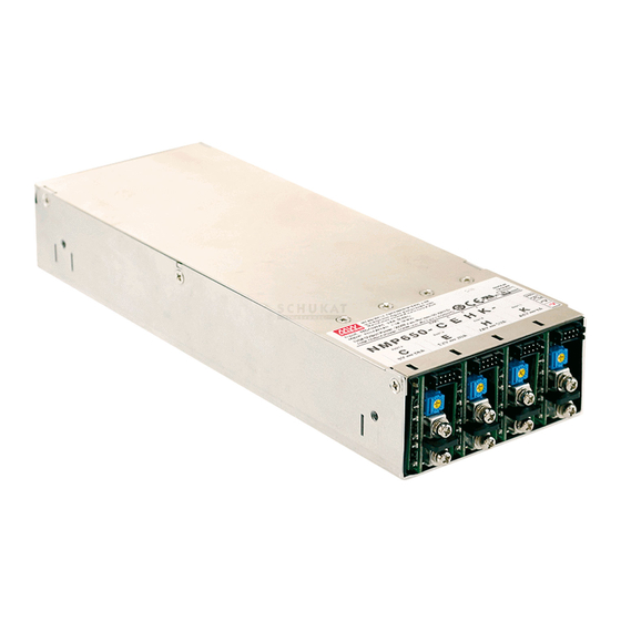
Product Description Description NMP is MEAN WELL's new generation intelligent modular power supply, bringing forth the state-of-the-art Front-End and NMS- 240 output module designs. This family offers output module configurability, intelligent control functions, and 1U low profile form factor. The NMP family also complies with both ITE and medical safety standards, offering the best flexibility for various types of applications. - Page 4 ----- ----- ◎ ◎ ◎ ◎ ◎ ◎ ◎ ◎ ◎ ◎ ◎ ◎ ◎ ◎ ◎ ◎ ◎ ◎ ◎ ◎ ◎ ◎ ◎ ※Code 00, 01, 02, 03, 06, 07, 10, 16 for NMP650/NMP1K2 ※Code 00~31 for NMP1K2...
-
Page 5: Notes On Output Configuration
Modules to be in parallel or series connection should be placed in adjacent slots. ◎ The combined operation output power of all modules must be less than the Front-End's rated maximum output power: 1200W for NMP1K2 and 650W for NMP650. Label Marking ... -
Page 6: Mechanism Of Output Modules
Pin No. Function Description +5V-AUX_P Auxiliary voltage output, 4.5~5.5V, referenced to pin 3 & 4(GND-P).The maximum load current is 2A (NMP1K2) or 1.5A (NMP650). GND-P Ground. TTL signal output for over temperature alarm. The maximum sourcing current is 10mA. T-Alarm High (4.5~5.5V): When the internal temperature exceeds the limit &... -
Page 7: Product Specifications
Connection for output voltage programming, referenced to pin 1&2 (GND) Positive sensing for remote sense. Negative sensing for remote sense. Product Specifications Front-End Specification MODEL NMP650 (4 Slots) NMP1K2 (6 Slots) VOLTAGE RANGE 90 ~ 264VAC 120 ~370VDC Note.6 FREQUENCY RANGE... -
Page 8: Output Module Specifications
Output Module Specification MODEL NMS-240-05 NMS-240-12 NMS-240-24 NMS-240-48 CONFIGURATION CODE DC VOLTAGE RATED CURRENT CURRENT RANGE 0 ~ 36A 0 ~ 20A 0 ~ 10A 0 ~ 5A 180W 240W 240W 240W RATED POWER OUTPUT (NMS-240) 100mVp-p 150mVp-p 150mVp-p 250mVp-p RIPPLE &... -
Page 9: Functions
5.Functions Input Voltage ◎ Input voltage range is 90~264VAC or 120~370VDC ◎ To ensure proper operation, input voltage must be within the specified range. An incorrect input voltage may cause the unit operate improperly, lose PFC function, or even damaged in worst case scenario. ◎... -
Page 10: Over-Temperature Protection And T-Alarm
Please turn off the AC power and remove the conditions causing fan-lock. If there are no observable causes for fan-lock, please remove the unit from your system and send back to our local distributor or MEAN WELL for repair. -
Page 11: Output Module Remote Sense
◎ Front-End and output modules have auxiliary power for control circuitry and low power peripherals. ※ Front-End: + 5V- Aux- P is 5V/ 2A (NMP1K2) or 5V/ 1.5A (NMP650) auxiliary output, referenced to GND- P. +5V-AUX-P CN32 ( PIN1 & 2) -
Page 12: Dc-Ok Signal And Led Indicator
Parallel Operation ◎ Up to 4 (NMP650) or 6 (NMP1K2) modules of the same output voltage rating may be connected in parallel. ◎ Before making the parallel connection, adjust the voltage of each module individually to the desired voltage, and ensure the difference in voltage is less than 0.2V. -
Page 13: Assembly
After removing the top cover, output modules may be installed or removed. Please refer to diagrams below for installation and removal instructions. For first time assembly, it is recommended to install in order from right to left, starting with slot 4 (NMP650) or slot 6 (NMP1K2). - Page 14 Mylar film Mylar film Note : Mylar films need to fold over the modules STEP 4: ◎ Once all modules have been installed or reconfigured, place the top cover back and secure with screws as shown below. While securing the top cover, ensure all modules are held secure by the notches and screws. Please set the electric screw driver's torque setting to 6kgf-cm.
- Page 15 STEP 6: ◎ Connect AC power to the NMP unit and test each module to ensure proper operation.The green LED indicator on module should light up. ◎ Measure the output voltage of each module and make sure it is within the specified output voltage tolerance range. If the load requires a different voltage that is within the specified voltage adjustment range, adjust the voltage by turning the SVR as shown below.
-
Page 16: Assembly Example
◎ In parallel operation, CS and GND pins of CN81 of all modules need to be connected in parallel. MEAN WELL offers connection accessories for 2 units (NMS-240-P2), 3 units (NMS-240-P3), 4 units (NMS-240-P4), 5 units (NMS-240-P5), and 6 units (NMS-240-P6). - Page 17 Place the top cover and secure with screws. : M3*3.3 Note: Screws each from left and right Top cove screws: M3*6 Apply the corresponding product model label to the Front-End top cover. SLOT1 CN81 ...
-
Page 18: Notes On Operation
115VAC (HORIZONTAL) INPUT VOLTAGE (VAC) 60Hz AMBIENT TEMPERATURE (℃) Figure 7-2 NMP1K2/NMP650 de-rating curves Warranty ◎ When operated under normal conditions, the NMP has a 5-year global warranty. Please do not change components or make modifications to the product, otherwise the warranty shall be void. -
Page 19: Appendix
Appendix Accessories A1.1 (±V) Parallel Connection Accessories Parallel Connection Accessory FAP-009 (For NMS-240, 2 units) FAP-010 (For NMS-240, 3 units) (CN81) A1.2 Parallel Connection Accessories NMS-240-P2 NMS-240-P3 (For NMS-240, 2units) (For NMS-240, 3units) 35mm 35mm 35mm UL1061 28AWG UL1061 28AWG UL1061 28AWG HRS DF11-10DS HRS DF11-10DS HRS DF11-10DS... - Page 20 A1.3 (±V) Series Connection Accessory Series Connection Accessory FAS-005 (For 1-slot modules: NMS-240) A1.4 Front-End Accessory NMP-CN32 (For NMP650/ 1K2, Front-End) 200mm UL1007 24AWG HRS DF11-06DS or equivalent HRS DF11-06DS PIN NO. Wire color Black Black Blue Gray Assignment GND-P...
- Page 21 N o . 2 8 , W u q u a n 3 r d R d . , W u g u D i s t . , N e w Ta i p e i C i t y 2 4 8 , Ta i w a n...
Need help?
Do you have a question about the NMP650 and is the answer not in the manual?
Questions and answers