
Related Manuals for Bosch Uni Condens 8000 F


Summary of Contents for Bosch Uni Condens 8000 F
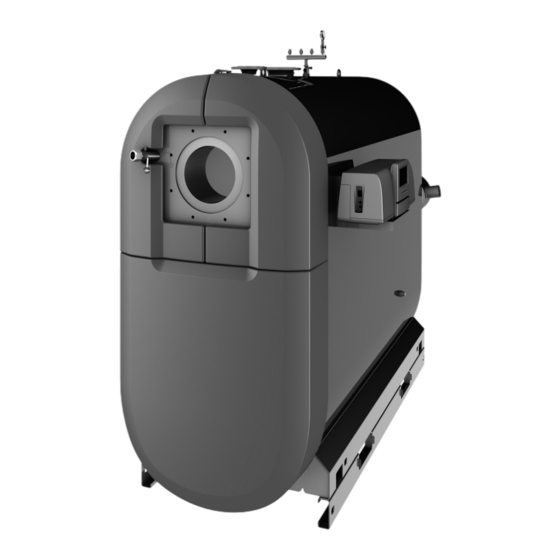
- Page 1 Installation and maintenance instructions for the contractor Floor standing condensing boiler Uni Condens 8000 F UC8000F 800...1200 kW...
-
Page 2: Table Of Contents
........19 Uni Condens 8000 F – 6720867056 (2016/10) -
Page 3: Table Of Contents
▶ Read the installation instructions (heat source, heating controller, etc.) before installation. ▶ Observe safety instructions and warnings. ▶ Observe national and regional regulations, technical rules and guidelines. ▶ Keep a record of all work carried out. Uni Condens 8000 F – 6720867056 (2016/10) - Page 4 The Health and Safety at Work Act 1974 and all other local regulations. Chemically aggressive substances can cause the device to rust, which would invalidate any warranty claim. Uni Condens 8000 F – 6720867056 (2016/10)
-
Page 5: Product Information
• Control unit ▶ Leave the installation instructions and the operating instructions with the user for Further optional accessories are listed on the Bosch Commercial and safekeeping. Industrial website. Uni Condens 8000 F – 6720867056 (2016/10) -
Page 6: Data Plate
Table 2 Abbreviations used on the data plate The Uni Condens 8000 F 800...1200 is also referred to in this manual as UC8000F 800...1200, boiler or heat source. Pictogram... - Page 7 [12] Port Return 1 (RK1) low temperature return (main return) [13] Return connection 2 (RK2), high temperature return [14] Inspection opening on the water side (both sides) [15] Flow safety line [16] Heating flow [17] Boiler safety assembly (accessories) [18] Lifting points Uni Condens 8000 F – 6720867056 (2016/10)
-
Page 8: Connections And Dimensions
2060 1040 1040 Flue gas outlet Ø D AAinside 1064 1193 1193 Combustion chamber Length 1904 1954 1954 Ø internal Burner door 1508 1653 1653 Blast tube Minimum depth Boiler flow Ø VK Uni Condens 8000 F – 6720867056 (2016/10) -
Page 9: Operation Conditions
(CFB/CC controllers with function modules). Table 7 Operation conditions It must be possible to check the number of burner starts, e.g. at the user interface, third-party control unit, building control system or burner control unit. Uni Condens 8000 F – 6720867056 (2016/10) -
Page 10: Safety Equipment
• Standard tools used by heating system installers and for gas and water installations. The boiler can be transported by crane, forklift truck, several pallet trucks or on heavy duty rollers. The following may also prove useful: • 1 torque wrench. Uni Condens 8000 F – 6720867056 (2016/10) -
Page 11: Transporting The Boiler With A Crane
Locking lugs (not suitable for lifting by crane) Table 8 Dimensions of the transport apertures Towing points for tow ropes Contact points for lifting with a trolley jack Base frame rail Contact points for lifting with a forklift truck Uni Condens 8000 F – 6720867056 (2016/10) -
Page 12: Moving The Boiler With 2 Pallet Trucks
Fig. 7 Removing the base frame ( fig. 1, [5], page 7). Base frame rails Cross beam screw ▶ Install the base frame at the installation location by following this process in reverse. Uni Condens 8000 F – 6720867056 (2016/10) -
Page 13: Requirements
▶ Provide isolating device. Combustion air vents Use of windows as combustion air vents is not permitted! Uni Condens 8000 F – 6720867056 (2016/10) -
Page 14: Requirement For The Control Unit
As the heat transfer medium has a higher viscosity and density than water, take the higher pressure drop through the pipework and other system components into account. Check the resistance of all plastic or non-metallic components in the system separately. Uni Condens 8000 F – 6720867056 (2016/10) -
Page 15: Notes On Installation And Operation
▶ Restrict the flow rate in the boiler to a temperature difference of at least 7 K. If the system is equipped with a dirt separator, it is not necessary to restrict the temperature difference. ▶ Size the pump correctly. Uni Condens 8000 F – 6720867056 (2016/10) -
Page 16: Installation
1) If using a flue gas silencer, take its installation dimensions into account. 2) Factor in dimension L (burner length) subject to burner overhang. 3) Dimensions also subject to the burner length LBR Table 11 Specified wall clearances (dimensions in brackets are minimum clearances) Uni Condens 8000 F – 6720867056 (2016/10) -
Page 17: Fitting Sound Insulation Strips
Due to utilization of the flue gas condensate in the heat source, the flue ▶ Level the boiler horizontally using the spirit level in the combustion system must be adapted to the flue gas condensate conditions. chamber. Uni Condens 8000 F – 6720867056 (2016/10) -
Page 18: Connecting The Venting System
If there are no varying return temperatures, return connection RK1 is used. ▶ Connect the heating system return to the appropriate boiler return connection RK1/RK2. ▶ Close off unused connections with a plug or dummy flange. Uni Condens 8000 F – 6720867056 (2016/10) -
Page 19: Connecting The Safety Valve
▶ For installation, adjustment and operation, refer to the documents provided by the manufacturer. ▶ Install the low water indicator in the supply flow adaptor piece or in the flow pipe directly downstream of the boiler in a vertical pipe. Uni Condens 8000 F – 6720867056 (2016/10) -
Page 20: Opening And Reversing The Burner Door
▶ Fit the washer [2]. ▶ Fit the Allen screw. ▶ Pre-tighten the Allen screw until the washer has a clearance of 60 mm towards the boiler front panel. ▶ Hook in the rocker arm. Uni Condens 8000 F – 6720867056 (2016/10) -
Page 21: Fitting The Burner (Accessory)
The burner door is hanging straight in the hinge. 0010014741-001 Fig. 16 Fitting the burner plate Burner door gasket Burner plate Hexagon screws and washers Uni Condens 8000 F – 6720867056 (2016/10) -
Page 22: Fitting The Burner To The Burner Plate
▶ Refer to the installation instructions of the relevant burner. ▶ Open the burner door ( chapter 6.9.1, page 20). ▶ Push a gasket ( fig. 17, [1], page 22) onto the burner connector. 0010014754-001 Fig. 17 Fitting the gasket gasket Uni Condens 8000 F – 6720867056 (2016/10) -
Page 23: Attaching The Data Plate
▶ Hook upper left front cover [1] into the holders on the boiler casing. 0010014742-001 Fig. 21 Fitting the control unit Control unit support 0010014762-001 Fig. 20 Fitting the front cover Upper l.h. front cover Upper r.h. front cover Lower front cover Uni Condens 8000 F – 6720867056 (2016/10) -
Page 24: Installing The Temperature Sensor
Fig. 23 Fitting the burner cable Temperature sensor immersion sleeve Cable conduit Control unit Strain relief Burner cable 010011598-002 Fig. 22 Inserting the plastic coil into the sensor pocket Compensating spring KPlastic coil Sensor retainer Sensor well Uni Condens 8000 F – 6720867056 (2016/10) -
Page 25: Control Unit
The system must be checked to find out whether the number of burner starts can be reduced. The customer service of the manufacturer can provide assistance with optimisation of the system. Uni Condens 8000 F – 6720867056 (2016/10) -
Page 26: Fitting The Control Unit
▶ Connect the burner cable to the control unit in accordance with the labelling on the plug-in strip. ▶ Make all electrical connections to the appropriate plug-in connectors according to the wiring diagram. Uni Condens 8000 F – 6720867056 (2016/10) -
Page 27: Control Unit Settings
4) The temperature demand of DHW heating is composed of the set DHW temperature and parameter "return temperature increase" in the DHW menu. Table 12 Adjustable parameters for CFB 810 and CFB 840 Uni Condens 8000 F – 6720867056 (2016/10) -
Page 28: Setting Control Unit Parameters
[3]. ▶ Screw the base of the casing to the control unit holder with 2 sheet- metal screws [1]. 0010014742-001 Fig. 30 Fitting the control unit Control unit support Uni Condens 8000 F – 6720867056 (2016/10) -
Page 29: Electrical Connection Of The Control Unit
▶ Offer up the back panel [4] to the lower housing [3] of the control unit and snap into place. 0010011782-001 Fig. 33 Preparing the cable entry Knock-outs Rear panel 0010004448-001 Fig. 32 Installation on boiler, fit back panel and snap into place Uni Condens 8000 F – 6720867056 (2016/10) - Page 30 LAN2 0010004448-001 Fig. 34 Fasten back panel to the base of the casing. Separate the back panel from the base of the casing. Rear panel 0010011783-001 Fig. 35 Set the control unit address Uni Condens 8000 F – 6720867056 (2016/10)
-
Page 31: Control Unit Settings
3) The temperature demand of DHW heating is composed of the set DHW temperature and parameter "boiler temperature increase" in the DHW menu. Table 14 Adjustable parameters for CC 8311 and CC 8312 Uni Condens 8000 F – 6720867056 (2016/10) -
Page 32: Setting Control Unit Parameters
( fig. 23, page 24). ▶ In the case of third party control units, match the sensor immersion sleeve to the diameter of the sensors used. ▶ Do not change the length of the immersion sleeve. Uni Condens 8000 F – 6720867056 (2016/10) -
Page 33: Commissioning
The available geodetic level calculated lies between the highest point of ▶ During operation, only fill the heating system via the filling facility in the consumer and the installation location of the pressure maintaining the heating system pipework (return). system. Uni Condens 8000 F – 6720867056 (2016/10) -
Page 34: Making The Heating System Operational
▶ Complete the commissioning report in the technical documentation ▶ Immediately correct all faults to prevent system damage. of the boiler, the control and burner. Annual inspection and service are part of the warranty terms. Uni Condens 8000 F – 6720867056 (2016/10) -
Page 35: Preparing The Boiler For Inspection And Maintenance
▶ Close and secure the burner door. Fig. 39 Removing the cover of the reversing chamber. Reversing chamber cover ▶ Undo the nuts and washers in the flue gas collector cover. ▶ Removing the cover. Uni Condens 8000 F – 6720867056 (2016/10) -
Page 36: Replacing The Flue Gas Collector Gasket
▶ Press diagonally abutting edges together leaving no gap. ▶ Cover the control panel with foil to prevent spray from entering it. ▶ Clean the boiler according to the instructions of the cleaning agent manufacturer. Uni Condens 8000 F – 6720867056 (2016/10) -
Page 37: Check And Correct The Operating Pressure
▶ If required, top up with water. Red needle Green marking Recently added fill or top-up water loses much of its volume in the first Pressure gauge needle few days because it releases gases. Uni Condens 8000 F – 6720867056 (2016/10) -
Page 38: Installations With Automatic Pressurisation Units
▶ Press burner reset button (see operating instructions of burner and control). If the burner still fails to start after three attempts, contact a contractor. 11.2 Other faults For other possible faults, see the installation and operating instructions of the control unit. Uni Condens 8000 F – 6720867056 (2016/10) -
Page 39: Safety Equipment
Safety equipment heat source Safety equipment Shut-off valve, flow/return Temperature controller Further safety accessories are listed on the Bosch Commercial and High limit safety cut-out Industrial website. Temperature capturing facility 13.1 Arrangement of minimum safety equipment in Diaphragm safety valve MSV 2.5 bar/3.0 bar or accordance with BS EN 12828:2012 Pressure relief valve HFS ≥... -
Page 40: Safety Equipment In Accordance With The Ec-Type Examination
Dirt traps must be installed near the lowest point of the heating system in an easily accessible position. Clean the dirt traps every time the heating system is serviced. Uni Condens 8000 F – 6720867056 (2016/10) -
Page 41: Appendix
1) Arithmetical flue gas temperature used for cross-sectional calculation according to EN 13384 (average value across product line). The actual flue gas temperature may differ from this, subject to burner setting and actual system temperature. Table 19 Operating temperatures 50/30 °C and 80/60 °C Uni Condens 8000 F – 6720867056 (2016/10) -
Page 42: Boiler Parameters
Fig. 44 Pressure drop on the water side Δp Pressure drop on the heating water side [mbar] Flow rate [m Uni Condens 8000 F 800...1200, boiler size 800 Uni Condens 8000 F 800...1200, boiler size 1000/1200 14.4 Commissioning report The boiler can be operated with an oil or gas burner. -
Page 43: Inspection And Maintenance Reports
▶ Check water records (e.g. amount of top-up water) in the operator's log. 13. Check the neutralising system. 14. Final check of the inspection work, take measurements and record values and test results. 15. Confirm professional commissioning. Company stamp/signature/date Table 21 Inspection record Uni Condens 8000 F – 6720867056 (2016/10) - Page 44 8. Final check of the maintenance work, take measurements See technical documentation for and record values and test results. burner. 9. Check the function and operational safety (safety equipment). 10. Confirm professional commissioning. Company stamp/signature/date Table 22 Heating system maintenance protocol Uni Condens 8000 F – 6720867056 (2016/10)
- Page 48 Bosch Thermotechnik GmbH Junkersstrasse 20-24 D-73249 Wernau www.bosch-thermotechnology.com...
Need help?
Do you have a question about the Uni Condens 8000 F and is the answer not in the manual?
Questions and answers