Table of Contents
Advertisement
Quick Links
PJC211/212/221/222
S-linkControl Panel
SIDE-POWER
Thruster Systems
Installation and user's manual
v 2.0.4
EN
PJC211
PJC212
PJC221
PJC222
SLEIPNER MOTOR AS
P.O. Box 519
N-1612 Fredrikstad
Norway
Tel: +47 69 30 00 60
Fax: +47 69 30 00 70
www.side-power.com
sidepower@sleipner.no
© Sleipner Motor AS version 2.0.4 2014
Advertisement
Table of Contents

Subscribe to Our Youtube Channel
Related Manuals for SLEIPNER MOTOR AS SIDE-POWER S-linkControl Panel PJC211


Summary of Contents for SLEIPNER MOTOR AS SIDE-POWER S-linkControl Panel PJC211
- Page 1 Installation and user's manual v 2.0.4 PJC211 PJC212 PJC221 PJC222 SLEIPNER MOTOR AS P.O. Box 519 N-1612 Fredrikstad Norway Tel: +47 69 30 00 60 Fax: +47 69 30 00 70 www.side-power.com sidepower@sleipner.no © Sleipner Motor AS version 2.0.4 2014...
-
Page 2: Table Of Contents
Sleipner and through a designated and approved interface, you are still required to also install an original Sidepower control panel to enable efficient troubleshooting if necessary DECLARATION OF CONFORMITY We, Sleipner Motor AS P.O. Box 519 N-1612 Fredrikstad, Norway declare that this product with accompanying standard remote... -
Page 3: Product Features
Product Features Control panel with S-link™ CAN-bus connection Product features For proportional thruster control with DC, AC and Hydraulic Thrusters • (Hydraulic thrusters PJC-221/222 only). • Finger tip control speed control with purpose designed joysticks • Hold - function for easy docking, runs thrusters at selected power (Dual joysticks PJC-212/222 only) •... -
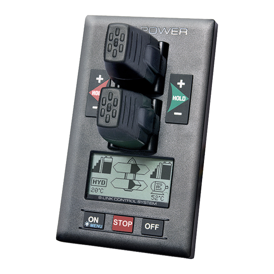
Page 4: Panel Layout & Functions
Panel layout & functions PJC-211 Speed control joystick for thruster Information display, see following pages for details. Press both “ON” but- tons simultanously to activate control panel. MENU Press to de-activate control panel or cancel or go back in menu system or MENU mute internal alarm buzzer. - Page 5 Panel layout & functions front s_v strek_PJC222.pdf 1 04.11.2010 11:05:34 PJC-221 Speed control joystick for thruster Information display, see following pages for details. Press and hold “ON” button for 1 second to activate control panel. MENU Press to de-activate control panel or cancel or STOP go back in menu system or mute internal alarm buzzer.
-
Page 6: Display In Normal Use
Display in normal use Status indicators for starboard Status indicators for bow bow thruster. Only shown in thruster. (Port bow thruster BOW-STB a dual bow thruster setup. in a dual bow thruster setup). Battery indicator will be Runtime indicator will be shown shown here in a single DC here in a single DC electric bow electric bow thruster setup. -
Page 7: Symbols Explanations
Symbols explanations DC Thrusters: Battery indicator. From 8.5V to 12V for 12V thrusters, 15V to 24V for 24V thrusters Motor temperature indicator. From 70°C/ 158°F to 130°C/266°F. Symbol shown when a DC Thruster is used in a dual bow or dual stern setup: Battery indicator. - Page 8 Symbols explanations INDICATORS showing thrust direction and amount: Thrust power and direction, Bow thruster(s) Input from bow joystick on this panel. The thrust indicator will be shown in this position on a single joystick panel if the thruster is defined as a bow thruster Thrust power and direction, Stern thruster(s) Input from stern joystick on this panel The thrust indicator will be shown in this position on a single joystick...
-
Page 9: Alarm Dc System
Alarms DC System front s_v strek_PJC222.pdf 1 04.11.2010 11:05:34 when there is a problem or a fault, the panel will show this alarm situation by changing LCD display backlight to red color. The panel will also change to show “Alarm Info” on the bottom of the screen, indicating that by pressing the corresponding button below, you will get information about what the problem is (examples below). -
Page 10: Alarms ( Ac And Hydraulic Thrusters )
Alarms (AC & hydraulic thrusters) when there is a problem or a fault, the panel will show this alarm situation by the LCD display in red color. All alarms will show in display when panel is turned OFF. This requires the S-link and other system devices have power. Critical alarms will activate internal and external buzzer (a long beep every 2 seconds). -
Page 11: Menu System
Menu system front s_v strek_PJC222.pdf 1 04.11.2010 11:05:34 Access menu system by pressing and holding Menu button for 3 seconds. Move around in menus by using joysticks. Follow instructions on the screen and press the buttons below the symbols indicated on LCD screen. STOP MENU PJC 212... -
Page 12: Menu System - Language - Stabilizer - Default Settings
Menu system LANGUAGE • Choose language by moving joystick: English, Norwegian, German, French, LANGUAGE Spanish, Italian and Danish. • Press the button below to set the language to the highlighted menu entry. A star (*) on each side indicates the laguage set. STABILIZER (Shown only for yachts equipped with a Side-Power Stabilizer system) Press the button below... -
Page 13: Setup Procedure
Setup procedure The setup procedure requires knowledge of the serial numer and location of all the S-link devices. Write this down in the form on the last page to have the information at hand when doing a manual setup. At the first startup of a new system, one of the two screens below will be shown: 1. -
Page 14: Menu System - Setup
Menu system - SETUP SETUP Move between menu items with the (stern) joystick. Press the button below to select the highlighted menu entry. Press the button below to return to the previous menu. Setup Setting done under SETUP will be sent to all other panels in the system. (Default in systems without stabilizers) SYSTEM DEVICES... - Page 15 Menu system - SETUP 1.2 Pump Control (PTO Mounted Pump) Values: Auto(default)/Always ON when «Pump Control» is set to «Auto», the system will automatically control SETUP load sharing between two PTO pumps by deactivating the second PTO pump when not needed (two PTO pumps/control valves required) to reduce heat generation in the system and save fuel/energy.
-
Page 16: Pdc 201
Menu system - SETUP AC system - Setup 2. PDC 201 (SAC Controller) Setup Press the button below to return to the previous menu. Press the button below to edit the selected parameter. (Default in systems without stabilizers) Parameter value will start to blink, use joystick to alter value. Press the button below to save edited parameter to device Press the button below... - Page 17 Menu system - SETUP 4.2 Direction Values: Normal (default)/Inverted Switches between Normal and Inverted running direction for the thruster SETUP (Default in systems without stabilizers) 4.3 Function Values: SR(V/L) ON/OFF, SRP 80/100, SRVP 130-210, SEP 30-240, SRVP 80/100, SRH, SRHP Setup the control unit behaviour - SR(V) ON/OFF: Retract thruster without speed controller (PPC800/PHC-024), SR61242 or SR150000.
-
Page 18: Rcrs-1
Menu system - SETUP 5. RCRS-1 (S-Link Radio Remote Receiver) Move between parameters with the (stern) joystick. SETUP Press the button below to return to the previous menu. Press the button below to edit the selected parameter. (Default in systems Parameter value will start to blink, use joystick to alter value. -
Page 19: Hold Calibration
Menu system - SETUP HOLD CALIBRATION Calibrates the HOLD-function to get balanced SETUP thrust from the bow and stern thruster. Incomplete. (Default in systems without stabilizers) To start calibration, press the “+”-Hold button in the desired direction. For a first time calibration, the thrusters will start at 70%. A system previously calibrated will start with the last amount of thrust set. -
Page 20: Menu System - Info
Menu system - INFO INFO • Move between menu items with the (stern) joystick. • Press the button below to select the highlighted menu entry. • Press the button below to return to the previous menu. INFO THRUSTER INFO Display info about the thusters in the system. The number of thrusters/controllers found is shown in the upper right corner of the display. -
Page 21: Menu System - Panel Setup
Menu system - PANEL SETUP PANEL SETUP • Move between parameters with the (stern) joystick. • Press the button below to return to the previous menu. • Press the button below to edit the selected parameter. PANEL • Parameter value will start to blink, use joystick to alter value. •... -
Page 22: Alarm Descriptions
Alarm descriptions Alarm Auto Errors shown in display Description Action code Reset Motor Overcurrent Motor current over 1400A. Thruster must be serviced by authorized personnel, reset or PPC800 power OFF/ON. Motortemp has been over Motor cool down below 115°C/239°F Motor Overtemp 130°C/266°F. - Page 23 Alarm descriptions Alarm Auto Errors shown in display Description Action code Reset Actuator Fault Actuator not getting any power. Check actuator connection or power to actuator. Reset alarm in alarm menu on PJC 211/212/221/222 or recycle power. Pos.Sensor Fault Retract position sensor fail. Check position sensor cables and for sensor damage.
-
Page 24: S-Link System Example
S-link system example PJC211/212/221/222 version 2.0.4 - April 2014... -
Page 25: Measurements
Measurements PJC211/212/221/222 version 2.0.4 - April 2014... -
Page 26: Connections
Connections Connections for optional external buzzer/audible alarm. External alarm/buzzer connection (S-link) Supply +12V / 24V DC Internal fuse/relay External alarm buzzer 12V / 24V DC - max 0,5A PJC211/212/221/222 version 2.0.4 - April 2014... -
Page 27: Notes
Note type, location and serial numbers Fill in the type, location and serial numbers of the S-link devices installed. Keeping this as a reference will make the setup procedure easier! S-link device Location Serial number (ie Thruster, AMS, PPC800 etc) (Bow, Bow-STB, Stern, Stern-STB) PJC211/212/221/222 version 2.0.4 - April 2014... -
Page 28: O. Box
Worldwide sales and service www.side-power.com SLEIPNER MOTOR AS P.O. Box 519 N-1612 Fredrikstad Norway Tel: +47 69 30 00 60 Fax:+47 69 30 00 70 www.side-power.com sidepower@sleipner.no...
Need help?
Do you have a question about the SIDE-POWER S-linkControl Panel PJC211 and is the answer not in the manual?
Questions and answers