Advertisement
Table of Contents
- 1 Table of Contents
- 2 Introduction and General Description
- 3 Helmet Sizing
- 4 Helmet Fitting and Operation
- 5 Inspections
- 6 Cleaning
- 7 Replacement Procedure 1: Energy-Absorbing Liner and Tpl
- 8 Replacement Procedure 2: Retention Assembly
- 9 Replacement Procedure 3: Earcups and Earphones
- 10 Replacement Procedure 4: Microphone Assembly
- 11 Replacement Procedure 5: Communications Cord
- 12 Replacement Procedure 6: Dual Visor Assembly
- 13 Illustrated Parts Breakdown
- 14 Other Visor Styles Available
- Download this manual
Advertisement
Table of Contents

Subscribe to Our Youtube Channel
Related Manuals for Gentex SPH-5


Summary of Contents for Gentex SPH-5
- Page 1 DUAL VISOR SPH-5 HELMET ASSEMBLY Fitting, Operation, and Maintenance Instructions...
-
Page 2: Table Of Contents
CONTENTS INTRODUCTION AND GENERAL DESCRIPTION ....HELMET SIZING ....... . HELMET FITTING AND OPERATION . -
Page 3: Introduction And General Description
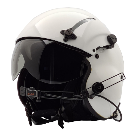
Helmet ® ® Assembly (Figure 1). The SPH-5 is a lightweight helmet assembly providing head protection, noise reduction, and communication enhancement for helicopter personnel. It consists of an impact-resistant helmet shell, a polystyrene energy-absorbing liner, a preformed thermoplastic liner (TPL ) that allows for custom-fitting, a yoke-style ®... -
Page 4: Helmet Sizing
HELMET SIZING Helmet sizing is based on head circumference. (Figure 2 shows how the crewmember’s head is measured for circumference.) Below are sizing parameters. HELMET SIZE MAXIMUM HEAD CIRCUMFERENCE (INCHES)* Small < 21.5 Regular 21.5 - 22.4 X-Large 22.4 - 23.5 XX-Large >... -
Page 5: Helmet Fitting And Operation
HELMET FITTING AND OPERATION In this procedure, you will ensure that the helmet is properly fitted to the crewmember. You will also familiarize the crewmember with operation procedures, including donning and doffing the helmet (Steps 1 and 8 respectively), adjusting the nape strap (Step 2), fastening and unfastening the chinstrap (Steps 3 and 7 respectively), operating the visors (Step 4), and operating the communications system (Step 5). - Page 6 WARNING For helmet stability, always tighten the nape strap and the chinstrap as snugly as possible when wearing the helmet. Failure to do so may result in injury. 2. Have the crewmember tighten the rear of the retention assembly by adjusting the hook-and-pile closure and tightening the nape strap through the adjustment buckle.
- Page 7 4. Have the crewmember lower and raise the visors as follows (to test operation and clearance): NOTE Visor knobs can be moved to either side of the visor housing depending on crewmember preference. See Page 23 for instructions. Inner Visor a.
- Page 8 CAUTION In Step 5, be sure to loosen the knurled nut on the swivel assembly before you rotate the boom assembly. Any attempt to rotate the boom assembly without loosening the knurled nut can cause the mounting hole in the helmet shell to become rounded;...
- Page 9 6. Evaluate the fit according to the following criteria: a. The earcups should surround the ears completely. b. The earseals should be compressed to the greatest degree possible without discomfort. c. The overall fit should be comfortable; no hot spots or pressure points should exist.
- Page 10 Adjustment #1: Earcup Centering 1. If the ears are not centered within the earcups, rotate the earcups within the retention assembly. Don the helmet, tighten the chinstrap, and recheck the earcup centering. 2. If the ears are not centered within the earcups after the earcups have been rotated, unfasten the chinstrap, doff the helmet, and remove the TPL as in Replacement Procedure 1, Step 1 (Page 13).
- Page 11 f. Reinstall the TPL as in Replacement Procedure 1, Step 7 (Page 14). g. Have the crewmember don the helmet and fasten the chinstrap. If the ears are now centered in the earcups, remove and store the helmet as required. If not, readjust the retention straps as necessary until the ears are centered in the earcups.
- Page 12 b. Attach spacer pad(s) to an earcup with the hook side of the pad facing the pile fastener on the earcup. Ensure that the fasteners are firmly attached. Repeat for the other earcup. 3. Don the helmet, tighten the chinstrap, and recheck the earseal compression. Add more spacer pads if needed until earseals are sufficiently compressed and a uniform, comfortable earcup fit is attained.
- Page 13 STEP RESULT/REMARKS WARNING TPL PLASTIC WILL BE HOT TO TOUCH. AVOID BURNING HANDS. WEAR GLOVES IF NECESSARY. 6. Squeezing sides of TPL together to clear earcups, place TPL in helmet with label and holes facing front. 7. Align TPL to protrude approximately - Ensure TPL is centered within the 1/4"...
-
Page 14: Inspections
STEP RESULT/REMARKS 11. Check distance between eye- - Distance should be approximately (but no brow and edge of helmet shell. more than) for optimum field of view. 12. Release pressure and remove - Remove tape from hook fasteners helmet. covered in Step 3. 13. - Page 15 Table 1. Periodic Inspection COMPONENT INSPECT FOR: APPLICABLE PROCEDURE Helmet Shell Cracks, holes, warping. Remove all components; install components in replacement shell. Cleanliness. Clean per instructions on the next page. Energy- Worn or loose hook Remove liner as in Replacement Absorbing fasteners.
-
Page 16: Cleaning
CLEANING Components of the SPH-5 helmet assembly can be cleaned as follows: Helmet shell and visor assembly (including visors, housing, tracks, and knobs): Wipe with clean, soft cloth dampened with mild soap solution; rinse with clean water and allow to air dry. -
Page 17: Replacement Procedure 2: Retention Assembly
REPLACEMENT PROCEDURE 2: RETENTION ASSEMBLY 1. Squeeze the sides of the TPL together and remove it from the helmet. 2. Remove the earcups from the retention assembly as in Replacement Procedure 3, Steps 1-3 (Page 16). 3. Remove the energy-absorbing liner as follows as in Replacement Procedure 1, Steps 3 and 4 (Page 14). -
Page 18: Replacement Procedure 3: Earcups And Earphones
5. Align the straps of the replacement retention assembly within the helmet and install the retention assembly using hardware removed in step 3. Applying Weldwood glue #281 to the first two threads of each screw, insert the screws through holes previously used. Tighten the screws securely, but do not overtighten. - Page 19 4. Carefully remove the earphone holder and the earphone from the earcup. (See Figure 16.) EARCUP EARSEAL SPACER EARCUP PADS FILLER PAD EARPHONE EARPHONE HOLDER Figure 16. Earcup Assembly 5. Remove the earphone from the earphone holder. Remove the cord leads from the earphone using a jeweler’s screwdriver or a hex wrench as required.
-
Page 20: Replacement Procedure 4: Microphone Assembly
REPLACEMENT PROCEDURE 4: MICROPHONE ASSEMBLY NOTE The microphone, microphone cord, boom, and swivel (Figure 18) are replaced as one assembly in this procedure. 1. Unplug the microphone cord from the connector at the rear of the helmet. 2. Remove the center screw attaching the boom swivel to the helmet. 3. -
Page 21: Replacement Procedure 5: Communications Cord
REPLACEMENT PROCEDURE 5: COMMUNICATIONS CORD 1. Unplug the microphone cord from the connector (Figure 19) at the rear of the helmet. 2. Cut the shrink tubing away from the connector using a razor blade or a knife. 3. Remove the connector and the two screws (Figure 19) securing the bracket and the mounting plate to the helmet shell. - Page 22 9. Apply Weldwood glue #281 or equivalent to the first two threads of the screw removed in Step 5. Secure the cord in the strain relief plate and attach the strain relief plate and the retention strap to the helmet shell using this screw and the associated washer and post.
-
Page 23: Replacement Procedure 6: Dual Visor Assembly
REPLACEMENT PROCEDURE 6: DUAL VISOR ASSEMBLY 1. Remove the four screws (two on each side) attaching the existing visor assembly to helmet shell. NOTES • Be sure to install the spacers and tracks on the side of the housing (right or left) for which they were configured. - Page 24 2. On the right side (as worn) of the visor housing, insert a replacement screw through each of the two holes. Place the right-hand detent spacer on the screws against underside of housing, followed by the right-hand upper track and the right-hand lower track in that order. Set the housing aside with the tracks and spacers facing upward so that the parts stay together.
- Page 25 8. Remove the right or left front housing screw where the inner visor knob is to be located. Use a screwdriver to lift the upper track just enough to provide clearance for the inner visor knob. Slide the inner visor into the lower tracks. 9.
-
Page 26: Illustrated Parts Breakdown
ILLUSTRATED PARTS BREAKDOWN This illustrated parts breakdown lists the most common repair parts for support of the SPH-5 Helmet. The parts listed are shown in Figure 21. The complete helmet assembly and part numbers are available from Gentex Corporation, Carbondale, PA., U.S.A., phone (570) 282-3550, fax (570) 282-8555. If your helmet configuration differs or if you need assistance, Call Air Crew Helmet Customer Service. - Page 27 Earphones, 1000-ohm 71B2383** Lt. weight Dual Visor Assy, Plain, Outer & Inner Visor 91B8069* Swivel Assy - Boom Support 67A1763 — Instruction Book TP0047 *Optional colors/visor configurations available. Contact Gentex aircrew helmet customer service for specifics. **Optional communications equipment also available.
-
Page 28: Other Visor Styles Available
Other SPH helmets are available in a variety of visor styles as shown in Figure 23: • SPH-5 with single visor assembly • SPH-5 with direct-mount ANVIS dual visor assembly • SPH-5 with quick-disconnect ANVIS dual visor assembly Contact GENTEX Corporation for more information. SINGLE VISOR ASSEMBLY... - Page 29 NOTES...
- Page 32 PUBLICATION TP0047 REV. 9 DECEMBER 2005...
Need help?
Do you have a question about the SPH-5 and is the answer not in the manual?
Questions and answers