
Related Manuals for Gentex HGU-56/P


Summary of Contents for Gentex HGU-56/P
- Page 1 OPERATION/MAINTENANCE INSTRUCTIONS HGU-56/P COMMERCIAL HELMET ASSEMBLY Ó2000 GENTEX Corporation...
-
Page 2: Table Of Contents
CONTENTS SECTION 1: INTRODUCTION AND GENERAL DESCRIPTION ..1 1-1. SCOPE ....... . . 1 1-2. -
Page 3: Section 1: Introduction And General Description
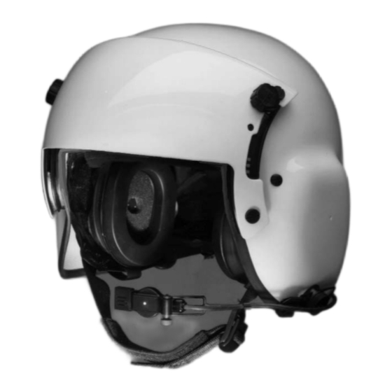
1-2. DESCRIPTION The HGU-56/P Commercial Helmet Assembly provides ear, eye, and head bump protection for aircrew personnel. Through a custom-fitting process, the HGU-56/P Commercial Helmet Assembly provides a stable mounting base for all modules and components. 1-2.1. Standard Components (Figure 1-1) The basic helmet assembly consists of the following standard components. -
Page 4: 1-2.2. Optional Components
QUICK-DISCONNECT ANVIS 1-2.2. Optional Components DUAL VISOR ASSEMBLY (Figure 1-2) Optional components include two kinds of ANVIS dual DIRECT-MOUNT ANVIS visor assemblies: one with DUAL VISOR ASSEMBLY a quick-disconnect plate that allows one-handed attachment and removal of the ANVIS mount, and one with a raised area for direct mounting of the ANVIS V-1 mount. -
Page 5: Helmet Sizing
2-2. HELMET SIZING Tools and Materials Required • Carpenter’s combination square • Ruler • Marker • Wood block (2 inches by 4 inches by 8 inches) • Adhesive-backed hook-and-pile fastener WARNING Proper fitting is essential to the functioning of the helmet, all of its components, and, consequently, the safety of the wearer. - Page 6 4. Referring to Figure 2-2, view (A), use a ruler to measure a distance 1-1/2 inches above wearer’s pupil. Using a marker, make a small mark at this point in the center of the wearer’s forehead; this is known as the forehead reference point (FRP).
-
Page 7: Anvis Quick-Disconnect Mount Installation (For Optional Anvis Quick-Disconnect Dual Visor Assembly)
2-3. ANVIS QUICK-DISCONNECT MOUNT INSTALLATION (For Optional ANVIS Quick-Disconnect Dual Visor Assembly) Before you can attach the ANVIS night vision goggles to the ANVIS dual visor assembly, you must modify the ANVIS mount. An optional kit contains the parts required for this modification. The kit includes a cable strain relief clamp, four locating pins (two top, two bottom), a backing plate, and a 1 x 1-inch piece of self-adhering hook fastener. - Page 8 6. Attach the 2-inch x 2-inch pile fastener tab (supplied with the ANVIS mounting hardware kit) to the visor housing as shown in Figure 2-4. This tab will anchor the connector. 7. Attach the two 2-inch x 3-inch pile fastener tabs (supplied with the ANVIS mounting hardware kit) to the back of the helmet as shown in Figure 2-4.
-
Page 9: Installing V-1 Mount On Optional Anvis Dual Visor Assembly
2-4. INSTALLING V-1 ANVIS MOUNT ON OPTIONAL DUAL VISOR ASSEMBLY Tools and Materials Required • #1 Cross-tip screwdriver • Jeweler’s screwdriver set • Dual Visor Assembly (88D7611-1) • V-1 ANVIS Mount • ANVIS Mounting Kit 1. Remove four thumbscrews that attach visor assembly to helmet;... - Page 10 7. Referring to Figure 2-7, remove two screws, washers, and posts attaching the power cord block and power cord cover to the visor housing. POWER CORD COVER SCREWS Figure 2-7. Power Cord Cover 8. Referring to Figure 2-8, remove the moleskin patch covering the power cord cover MOLESKIN PATCH...
- Page 11 CAUTION When reinstalling the power cord cover, be careful to install the screws just snugly enough to secure the cover. Tightening the screws too much may damage the cover. 11. Referring to Figure 2-9, reattach the power cord cover and the power RED DOT cord block to the visor housing with...
- Page 12 14. Position visor housing assembly on helmet, and start four thumbscrews into helmet to attach visor assembly as shown in Figure 2-11. After all four thumbscrews are started, tighten them. THUMBSCREW 15. Referring to Figure 2-12, attach two 2-inch x 3-inch pile fastener pieces (supplied in the ANVIS mounting kit) to the helmet as follows:...
-
Page 13: Helmet Fitting
2-5. HELMET FITTING WARNING Proper fitting is essential to the functioning of the helmet, all of its components, and, consequently, the safety of the wearer. Take as much time as necessary to fit the helmet precisely. Use extreme care in taking measurements and checking fit. - Page 14 3. Align the edge of the helmet with the FRP (marked in the previous procedure). 4. Adjust the earcups so that they cover the wearer’s ears. If earcup EARSEAL pressure is too great without fitting pads, select the next larger helmet size.
- Page 15 10. If fit is too loose, try a smaller-size helmet and repeat steps 2 through 9. NOTE If the wearer cannot be fitted according to these fitting instructions, contact GENTEX Corporation. Figure 2-21. Headband Fitting 11. Repeat steps 6 through 9 for a final fit Pads check.
-
Page 16: Tpl Custom Fitting
2-5. TPL CUSTOM-FITTING Equipment, Tools, and Materials Required • Convection oven • Oven thermometer • Ruler • Timer • Masking tape • Cotton gloves • Helmet with TPL to be fitted WARNING Proper fitting is essential to the functioning of the helmet, all of its components, and, consequently, the safety of the wearer. - Page 17 CAUTION Before you place the TPL in the oven, ensure that the cover is attached properly to the plastic layers (not on backwards). 2. Place TPL in center of rack in heated oven, cloth side on rack. 3. Ensure that oven stabilizes at temperature listed in Step 1 before starting timed sequence.
- Page 18 9. Squeezing sides of TPL together to clear earcups, install liner in helmet as shown in Figure 2-23. Ensure that label and holes are positioned toward front of helmet. 10. Have wearer hold helmet upside down. Insert TPL so that the front edge extends approximately 1/4"...
- Page 19 13. Have wearer pull downward with hands on top of the helmet until it is seated firmly on the head. Lower visor to check nose centering and clearance. Fasten chinstrap and nape strap as tightly as possible, without causing discomfort, to optimize the wearer’s peripheral vision. Have wearer maintain as much downward pressure as possible, without causing discomfort, for 3-5 minutes.
-
Page 20: Section 3: Operation
SECTION 3: OPERATION Operation of the HGU-56/P Commercial Helmet consists of donning/ removing the helmet and operating the components. 3-1. DONNING/REMOVING HELMET WARNING When donning helmet, ensure that nape strap pad is completely pulled down and that the keeper tab is taut. Failure to do so will decrease helmet stability and may cause injury to the wearer. -
Page 21: Operation Of Components
3-2. OPERATION OF COMPONENTS 3-2.1. Fastening and Adjusting Chinstrap (Figure 3-2) WARNING ALWAYS wear the helmet with the chinstrap properly attached and adjusted. Failure to secure the chinstrap will decrease helmet stability and may cause injury to the wearer. 1. Fasten chinstrap by inserting the toggle through the square receiver, and allow the toggle to rotate to the locking position. -
Page 22: 3-2.2. Adjusting Nape Strap
3-2.2. Adjusting Nape Strap (Figure 3-3) 1. Adjust the nape strap pad (1) position using nape strap pull-tabs (2). Tighten by grasping the two tabs, pulling to the back, and then pulling from side to side until the nape strap is snug. NOTE When the nape strap pad is BUCKLES... -
Page 23: Section 4: Maintenance
CAUTION When performing Step 3, be sure to loosen the knurled nut on the swivel assembly before you rotate the boom assembly. Any attempt to rotate the boom assembly without loosening the knurled nut can cause the mounting hole in the helmet shell to become rounded; consequently, the boom assembly will not be held in place. - Page 24 TABLE 4-1. PREVENTIVE MAINTENANCE CHECKS AND SERVICES B - Before (pre-flight) A - After (post-flight) C - Every 120 calendar days ITEM INTERVAL ITEM TO BE INSPECTED/ NOT FULLY MISSION PROCEDURE CAPABLE IF: Helmet shell. WARNING Do not repair or use any helmet that is damaged beyond the limits set forth in this PMCS chart.
- Page 25 TABLE 4-1. PREVENTIVE MAINTENANCE CHECKS AND SERVICES (Continued) B - Before (pre-flight) A - After (post-flight) C - Every 120 calendar days ITEM INTERVAL ITEM TO BE INSPECTED/ NOT FULLY MISSION PROCEDURE CAPABLE IF: Earcups Check fit. Earseals are not properly compressed around wearer’s ears.
- Page 26 TABLE 4-1. PREVENTIVE MAINTENANCE CHECKS AND SERVICES (Continued) B - Before (pre-flight) A - After (post-flight) C - Every 120 calendar days ITEM INTERVAL ITEM TO BE INSPECTED/ NOT FULLY MISSION PROCEDURE CAPABLE IF: Visor assembly. Check visors for dirt or Dirt or scratches interfering scratches.
-
Page 27: Troubleshooting
4-2. TROUBLESHOOTING Table 4-2 provides an index of common malfunctions of helmet components and directs you to the procedures required to eliminate those malfunctions. When examining this table, keep the following in mind: 1. You should first find the malfunction that most closely describes the problem, then perform the tests, inspections, and corrective actions in the order in which they are listed. - Page 28 Table 4-2. Aviation Unit Maintenance Troubleshooting Procedures (continued) MALFUNCTION TEST OR INSPECTION CORRECTIVE ACTION 3. UNABLE TO FASTEN OR ADJUST CHINSTRAP. Inspect retention assembly for defective hardware or webbing. Replace retention assembly in accordance with paragraph 4-3.3. 4. UNABLE TO ADJUST NAPE STRAP. Inspect retention assembly for defective hardware or webbing.
- Page 29 Table 4-2. Aviation Unit Maintenance Troubleshooting Procedures (continued) MALFUNCTION TEST OR INSPECTION CORRECTIVE ACTION Step 3. Using a multimeter, refer to Figure 4-1 and perform Test 1 in accordance with the chart below. If no failure is detected, proceed to step 4. If a failure is detected, replace the communication cord in accordance with paragraph 4-3.6.
- Page 30 Table 2. Aviation Unit Maintenance Troubleshooting Procedures (continued) MALFUNCTION TEST OR INSPECTION CORRECTIVE ACTION Step 4. Using a multimeter, refer to Figure 4-2 and perform Test 2 in accordance with the chart below. If no failure is detected, the communication cord is working.
-
Page 31: Component Replacement
4-3. COMPONENT REPLACEMENT 4-3.1. Energy-Absorbing Liner Tools and Materials Required • Flat-tip screwdriver • Icing spatula • Energy-absorbing liner NOTE Before performing this procedure, disengage the chinstrap buckle, and loosen nape strap pad adjustment. This will ease removal of the energy-absorbing liner. - Page 32 NOTE Removing the energy-absorbing liner may require some practice. 5. Referring to Figure 4-5, use a spatula to separate the hook-and-pile fasteners attaching the energy-absorbing liner to the helmet shell. Following the contour of the helmet shell, carefully slide the energy-absorbing liner out of the helmet.
-
Page 33: 4-3.2. Tpl Cloth Cover
4-3.2. TPL Cloth Cover Tools and Materials Required • Scissors • Double-sided tape • Cloth Cover Removal 1. Detach the earcups from earcup retainer pads by disengaging hook-and-pile fasteners, and passing them through the retention straps. Allow earcups to hang outside the helmet by communications cord. 2. -
Page 34: 4-3.3 Retention Assembly
4-3.3. Retention Assembly Tools and Materials Required • Screwdriver, flat-tip • Spatula • Retention Assembly Removal NOTE Ensure that the chinstrap is disengaged from the D-rings, and loosen nape strap pad adjustment. This will provide easier access to Figure 4-7. Removing TPL the helmet for installation. - Page 35 6. Inspect the energy- SCREWS absorbing liner in accordance with Table 4-1; replace if necessary following 4-3.1. 7. Referring to Figure 4-10, remove the remaining two pan-head screws, spring washers, and posts attaching the retention assembly to each side of the helmet shell.
-
Page 36: 4-3.4. Earcup Assembly
4-3.4. Earcup Assembly Tools and Materials Required • Jeweler’s screwdriver set • Earcup Assembly Removal 1. Referring to Figure 4-11, remove the earcup (1); allow it to hang by the communications cord. 2. Remove the earseal (5) from the earcup by stretching it carefully over the lip of the earcup shell. - Page 37 CAUTION When removing communications cord leads from the earcup shell, handle the grommet only; do not pull on the wires. 7. Carefully remove the grommet from the earcup shell and pull the communications cord leads through the hole. 8. Inspect all components in accordance with Table 1, and replace as necessary.
-
Page 38: 4-3.5. Microphone Boom
4-3.5. Microphone Boom Tools and Materials Required • Screwdriver, flat-tip • Screwdriver, cross-tip • Microphone boom Removal 1. Referring to Figure 4-12, remove the knurled thumbscrew attaching the microphone to the boom. 2. Remove the boom clip attaching the microphone cord to the boom. 3. -
Page 39: 4-3.6. Communications Assembly
4-3.6. Communications Assembly Tools and Materials Required • Screwdriver, flat-tip • Screwdriver, cross-tip • Spatula • Jeweler’s screwdriver set • Earphone • Microphone • Cord assembly • Boom swivel assembly Figure 4-13. Removing TPL Removal SCREW 1. Detach the earcups from earcup retainer pads by disengaging hook-and-pile fasteners and passing them through the retention straps. - Page 40 7. Unplug the microphone cord from POST the communications jack at the PLATE rear of the helmet. KNOT HELMET 8. Referring to Figure 4-16, remove the screw, washer, and post WASHER attaching the communications cord strain relief plate to the SCREW helmet shell.
- Page 41 CAUTION When removing communications cord leads from the earcup shell, handle the grommet only; do not pull on the wires. 14. Remove the grommet from each earcup shell. Holding the grommet, pull the communications cord leads through the hole in each earcup shell. 15.
- Page 42 3. Remove the strain relief plate from the communications cord by untying the cord. 4. From the outside of the helmet, pass the entire communications cord though the hole in the rear of the helmet shell, leaving only the microphone connector with the mounting bracket and the grommet outside the helmet.
- Page 43 10. Insert the grommet into the hole in the earcup shell. For easier insertion, wet the grommet with plain water if needed. 11. Insert the communications cord leads into the receiver and tighten the two set screws. 12. Insert the filler pad into the earcup, ensuring that the slit in the pad is positioned toward the grommet.
-
Page 44: 4-3.7. Dual Visor Assembly
4-3.7. Dual Visor Assembly Tools and Materials Required • Jeweler’s screwdriver set • Screwdriver, cross-tip • Dual visor assembly Removal NOTE Screws, retaining rings, tracks, and bushings are shown on one side only in Figure 4-20. A similar configuration exists for the other side. 1. - Page 45 Installation NOTE When installing lenses, ensure lens guides are seated in track grooves. Ensure bushing mates with locking notch in lower track to prevent rotation when installing or removing thumbscrews. If energy-absorbing liner was removed, replace it as directed in paragraph 4-3.1.
-
Page 46: Section 5: Parts List
SECTION 5: PARTS LIST Following is a list of replacement parts for the HGU-56/P Commercial Helmet Assembly. Included are quantities and part numbers. Numbers in the ITEM NO. column correspond to number callouts in the accompanying illustrations. For more information, contact: GENTEX Corporation P.O. - Page 47 ITEM NO. DESCRIPTION QTY. PART NO. — Helmet Assembly, HGU-56/P Commercial, XX-Small 95D9317-1 Helmet Assembly, HGU-56/P Commercial, X-Small 95D9317-2 Helmet Assembly, HGU-56/P Commercial, Small 95D9317-3 Helmet Assembly, HGU-56/P Commercial, Medium 95D9317-4 Helmet Assembly, HGU-56/P Commercial, Large 95D9317-5 Helmet Assembly, HGU-56/P Commercial, X-Large...
- Page 48 Figure 5-2. Dual Visor Assembly, Plain...
- Page 49 ITEM NO. DESCRIPTION QTY. PART NO. — Dual Visor Assembly, Plain 95B9301-3 Visor Housing, Plain, Aircraft Green 88D7612-1 Visor Housing, Plain, White 88D7612-2 Inner Visor, Clear 88D7618-1 Outer Visor, Neutral 88D7619-1 — Outer Visor, Gradient (Not Shown) 95A9302-1 Lower Track, Left-Hand 88D7615-1 —...
- Page 50 Figure 5-3. Earcup Assembly ITEM NO. DESCRIPTION QTY. PART NO. — Earcup Assembly 98C10311-1 Shell, Earcup Assembly 98C10337-1 Filler Pad 97B9974-1 Receiver Retainer 83C6573 Earseal 98C10311-1...
- Page 51 Figure 5-4. TPL ITEM NO. DESCRIPTION QTY. PART NO. — TPL, XX-Small 85D7087-15 TPL, X-Small 85D7087-16 TPL, Small 85D7087-17 TPL, Medium 85D7087-18 TPL, Large 85D7087-19 TPL, X-Large 85D7087-20 Layer Assembly, Preformed, XX-Small 89D7779-1 Layer Assembly, Preformed, X-Small 89D7779-2 Layer Assembly, Preformed, Small 89D7779-3 Layer Assembly, Preformed, Medium 89D7779-4...
- Page 52 Figure 5-5. ANVIS Quick-Disconnect Dual Visor Assembly...
- Page 53 ITEM NO. DESCRIPTION QTY. PART NO. — Dual Visor Assembly, Quick-Disconnect, ANVIS Visor Housing Assembly, Aircraft Green 95C9240-1 Visor Housing Assembly, Coast Guard Blue 95C9240-2 Visor Housing Assembly, White 95C9240-3 Visor Housing Assembly, O.D. 95C9240-4 Inner Visor, Clear 88D7618-1 — Inner Visor, Neutral (Not Shown) 96A9416-1 Outer Visor, Neutral...
- Page 54 Figure 5-6. ANVIS Dual Visor Assembly...
- Page 55 ITEM NO. DESCRIPTION QTY. PART NO. — Dual Visor Assembly, ANVIS 88D7611-1 Visor Housing 88D7613 Inner Visor, Clear 88D7618-1 Outer Visor, Neutral 88D7619-1 — Outer Visor, Clear (Not Shown) 95A9302-2 Lower Track, Left-Hand 88D7615-1 — Lower Track, Right-Hand (Not Shown) 88D7615-2 Middle Track, Left-Hand 88C7616-1...
- Page 56 INDEX ANVIS dual visor assembly, quick-disconnect mount description ........1 mount installation .
- Page 57 INDEX (Continued) Earcup spacer pads ........12 Earcup retaining pads description .
- Page 58 NOTES...
- Page 59 NOTES...
- Page 60 PUBLICATION TP0113 REV. 4 MARCH 2000...
Need help?
Do you have a question about the HGU-56/P and is the answer not in the manual?
Questions and answers