
Related Manuals for Gentex HGU-56/P


Summary of Contents for Gentex HGU-56/P
- Page 1 Operation and Maintenance Instructions HGU-56/P COMMERCIAL HELMET ASSEMBLY 2010 GENTEX Corporation...
- Page 3 Warnings and Cautions precisely. When you replace components or install additional components on Gentex products, always use genuine factory-new Gentex parts. This will ensure a correct fit and maintain the safety of the product. Use of non-Gentex parts (salvage, refurbished, etc.) for replacement or additional installation will void any product warranty and may...
-
Page 5: Table Of Contents
Contents OVERVIEW ........1 SECTION 1: INTRODUCTION AND GENERAL DESCRIPTION . - Page 6 Contents (continued) SECTION 3: MAINTENANCE ......39 3-1. PREVENTIVE MAINTENANCE AND CLEANING ....39 3-1.1.
-
Page 7: Overview
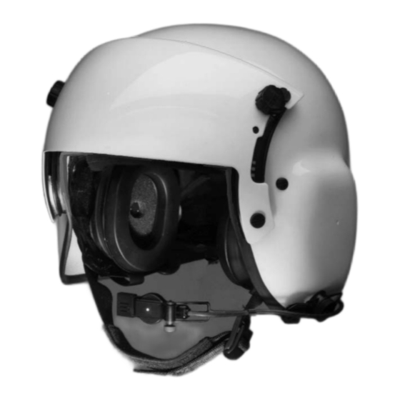
SECTION 1: INTRODUCTION AND GENERAL DESCRIPTION 1-1. SYSTEM DESCRIPTION The HGU-56/P Commercial Helmet Assembly (Figure 1-1) provides ear, eye, and head bump protection for aircrew personnel. Through a custom-fitting process, the HGU-56/P Helmet provides a stable mounting base for all modules and components. -
Page 8: Standard Components
Earcup spacer pad kit Dual visor assembly Helmet shell Energy-absorbing liner Nape pad Earcup (earphone inside) Boom and microphone Earcup retaining pad Communications cord Chin strap Figure 1-2. Standard Components of HGU-56/P Commercial Helmet is a registered trademark of GENTEX Corporation. -
Page 9: Optional Components
HGU-56/P. • Flex boom. Permits ease and flexibility for positioning the microphone. -
Page 10: Section 2: Preparation For Use
SECTION 2: PREPARATION FOR USE 2-1. SERVICE UPON RECEIPT This section contains instructions regarding the tasks to be performed upon receipt of the helmet. These tasks include unpacking and inspecting unpacked equipment. 2-1.1. Unpacking 1. Open the over pack carton and remove all unit pack cartons. Unit pack cartons are labeled according to their contents. -
Page 11: Selecting Helmet Size
2-2. SELECTING HELMET SIZE Tools and Materials Required • Carpenter’s combination square • Ruler • Marker • Wood block (2 inches by 4 inches by 8 inches) • Adhesive-backed hook-and-pile fastener Proper fitting is essential to the functioning of the helmet, all of its components, and, consequently, the safety of the wearer. - Page 12 3. Have the wearer stand with the back of the head against the block. Ensure that the wearer's posture and body alignment are as straight as possible. The wearer should hold his or her head in a comfortable position while focusing on a point directly ahead at eye level.
-
Page 13: Installing Optional Components
Installing Maxillofacial Shield: Paragraph 2-3.8 (Page 21) When you replace components or install additional components on Gentex products, always use genuine factory-new Gentex parts. This will ensure a correct fit and maintain the safety of the product. Use of non-Gentex parts (salvage, refurbished, etc.) for replacement or additional installation will void any product warranty and may... -
Page 14: 2-3.1 Installing Scl
2-3.1 Installing SCL To install the SCL, you remove the TPL from the helmet and insert the SCL in place of the TPL. Tools and Materials Required SCL in one of the following sizes (to match helmet size): • 02D11531-8 (XX-Small) Figure 2-3. -
Page 15: 2-3.2 Installing Optional Anvis Dual Visor Assemblies
2-3.2 Installing Optional ANVIS Quick-disconnect Dual Visor Assemblies (Quick-Disconnect or Direct-Mount) Direct-mount Both types of ANVIS dual visor assemblies (quick-disconnect and direct mount, Figure 2-6) are installed in the same manner (after the existing dual visor assembly is removed). Tools and Materials Required Figure 2-6. -
Page 16: 2-3.3 Installing Anvis Attachment Kit (For Quick-Disconnect Anvis Dual Visor Assembly)
2-3.3 Installing ANVIS Attachment Kit (for Quick-Disconnect ANVIS Dual Visor Assembly) Before you can attach the ANVIS night vision goggles to the ANVIS dual visor assembly, you must modify the ANVIS mount. An optional kit (Figure 2-9) contains the parts required for this modification. - Page 17 6. Attach the 2 x 2-inch pile fastener (supplied with the ANVIS mounting hardware kit) to the visor housing at the front of the helmet as shown in Figure 2-10. This fastener will anchor the connector. 7. Attach the two 2 x 3-inch pile fasteners (supplied with the ANVIS mounting hardware kit) to the back of the helmet as shown in Figure 2-10.
-
Page 18: 2-3.4 Installing Anvis Attachment Kit (For Direct-Mount Anvis Dual Visor Assembly)
2-3.4 Installing ANVIS Attachment Kit (for Direct-Mount ANVIS Dual Visor Assembly) Moleskin patches Tools and Materials Required • #1 Cross-tip screwdriver Pile fasteners • Jeweler’s screwdriver set • Dual Visor Assembly (88D7611-1) • V-1 ANVIS Mount • ANVIS Attachment Kit (93A8654) Procedure Screws In this procedure, you will use the ANVIS... - Page 19 Power cord cover Back of housing Screws Figure 2-14. Power Cord Cover 5. Referring to Figure 2-14, Moleskin patch remove the two screws, Inside of housing washers, and posts attaching the power cord block and power cord cover to the visor housing.
- Page 20 CAUTION When you install the screws in Step 10, be careful to tighten the screws just snugly enough to secure the cover. Tightening the screws too much may damage the cover. 10. Referring to Figure 2-17, reattach the power cord cover and the power cord block to the visor housing with the screws, washers, and posts removed in Step 8.
- Page 21 13. Position visor housing assembly Thumbscrew on helmet, and start four (four total) thumbscrews into helmet to attach visor assembly as shown in Figure 2-19. After all four thumbscrews are started, tighten them. 14. Referring to Figure 2-20, attach two 2-inch x 3-inch pile fastener pieces (supplied in the ANVIS mounting kit) to the helmet as follows:...
-
Page 22: 2-3.5 Installing High-Contrast Visor
2-3.5 Installing High-Contrast Visor The high-contrast visor is an outer visor that you install in place of the existing outer visor on the dual visor assembly. Follow these steps to Thumbscrew install the high-contrast visor. (four places) Tools and Materials Required High-contrast visor (95A9302-5) Helmet post Procedure... - Page 23 4. Referring to Figure 2-25, remove the existing outer visor as follows: a. Push the outer visor knob outward, and move the knob Outer visor knob downward along the tracks. Tracks b. Lift the upper track slightly to provide clearance for the Outer visor (remove) knob.
-
Page 24: 2-3.6 Installing Flex Boom Microphone
2-3.6 Installing Flex Boom Microphone In this procedure, you will remove the existing wire boom microphone from the helmet and install the flex boom microphone with its associated hardware kit (Figure 2-28). Tools and Materials Required Hardware kit • Flex boom (03B11804-16B) •... - Page 25 3. Referring to Figure 2-31, do the following: a. From outside the helmet, insert the screw through the flat washer, the flex boom mount, and the microphone attachment hole in the helmet. b. From inside the helmet, insert the nut through the lock washer, and attach the nut to the screw.
-
Page 26: 2-3.7. Installing Coiled Communications Cord
2-3.7. Installing Coiled Communications Cord NOTE: See Figure 2-32 for a comparison of the standard communications cord and the coiled communications cord. To install the coiled communications cord (87B7491-2), you must first remove the standard communications cord. This requires you to disassemble and remove several components from the helmet. -
Page 27: 2-3.8 Installing Maxillofacial Shield (Mfs)
2-3.8 Installing Maxillofacial Shield (MFS) To install the MFS (Figure 2-33), you must install hardware on the helmet for attachment of the shield. (If ANVIS goggles are used, you might also need to trim the shield to accommodate the goggles; refer to Paragraph 2-5 on Page 35.) Tools, Equipment, and Materials Required •... - Page 28 6. With the compass set to the appropriate value as specified Post in Step 5, position the point of the compass below the lower dual visor assembly post on one side of the helmet, and draw an arc as shown in Figure 2-35 to intersect with the first arc.
- Page 29 12. Referring to Figure 2-36, Drilled hole Striker attach a striker to one side Post of the helmet by using one Screw screw and a post through the lower hole of the striker and the drilled hole in the Helmet helmet, applying a drop of white glue to the threads of Figure 2- 36.
- Page 30 16. Referring to Figure 2-39, adjust the MFS position as Inner visor knob follows: a. Lower the inner (clear) visor to the full down position. (Push the inner visor knob outward and down.) b. Push up or down on the MFS so that an even, Overlap between visor and MFS approximately 1/16-inch...
- Page 31 • Wear eye-protective goggles when drilling holes in Steps 18 and 19 to prevent eye injury. • Use the 2x4 block of wood as described in Steps 18 and 19 to prevent hand injury. CAUTION • Be careful not to damage any components inside the helmet when performing Steps 18 and 19.
- Page 32 20. Rotate the strikers back to their previous positions. Referring to Figure 2-40, install the remaining screws and posts through the upper Post Screw Screw Post striker holes and the newly drilled holes to attach the strikers, applying a drop of white glue to the threads of each screw.
-
Page 33: Helmet Fitting And Operation
2-4. HELMET FITTING AND OPERATION Following is the procedure for donning and fitting the helmet, operating the helmet components, and removing the helmet. Tools and Materials Required • Needle and thread • Small cross-tip screwdriver Proper fitting is essential to the functioning of the helmet, all of its components, and, consequently, the safety of the wearer. - Page 34 When donning the helmet, ensure that nape strap pad is completely pulled down and that its attachment tab is taut. Failure to do so will decrease helmet stability and may cause injury to the wearer. CAUTION When donning or removing the helmet, flex the helmet just enough to clear the head. Excessive flexing may damage the helmet.
- Page 35 5. Adjust the earcups so that they cover the wearer’s ears. Ask the wearer if the ear is centered in the earcup. NOTE: Earseals (Figure 2-45) should be compressed evenly and to the greatest degree possible without causing discomfort. (Proper earseal compression may be indicated by a visible ring impression around the ear when the helmet is removed.
- Page 36 ALWAYS wear the helmet with the chinstrap properly attached and adjusted. Failure to secure the chinstrap will decrease helmet stability and allow the helmet to be forced off of the head during flight operations, resulting in possible injury or death. 7.
- Page 37 9. Referring to Figure 2-50, lower the visors (to check centering and nose clearance) as follows: a. Use the left-hand knob to move the outer visor. To use the visor knob, brace your thumb against the visor track, squeeze the knob with your forefinger, and move the knob down or up.
- Page 38 12. Connect the helmet communications system as Communications cord connector follows: a. Referring to Figure 2-51, ensure that the microphone cord is plugged into the communications cord Microphone cord plug connector at the rear of the helmet. b. Plug the helmet communications cord into the aircraft communications device.
- Page 39 14. If the MFS is used, refer to Figure 2-53 and check operation as follows: a. To attach the MFS, position the pin on one side of the MFS into the slot of the striker, and flip the latch against the helmet shell. Ensure that the latch is locked in place. Repeat for the other side.
- Page 40 17. After the first flight, recheck and adjust as necessary the helmet straps, TPL (or SCL), and earcups as necessary to achieve a snug fit. NOTE: If the wearer cannot be fitted according to these fitting instructions, contact Gentex Corporation.
-
Page 41: Trimming Mfs For Anvis Compatibility
TRIMMING MFS FOR ANVIS COMPATIBILITY If the night vision goggles contact the MFS (as described in the fitting procedure), trim the MFS following the procedure below. Equipment, Tools, and Materials Required • Pencil • Rotary tool kit • Drum, sanding •... -
Page 42: Tpl Custom-Fitting
2-6. TPL CUSTOM-FITTING Equipment, Tools, and Materials Required • Convection oven • Oven thermometer • Ruler • Timer • Masking tape • Cotton gloves • Helmet with TPL to be fitted Proper fitting is essential to the functioning of the helmet, all of its components, and, consequently, the safety of the wearer. - Page 43 3. Ensure that the oven stabilizes at the temperature listed in Step 1 before starting the timed sequence. 4. Set the timer, stopwatch, or equivalent for 10 minutes. Heat the TPL for approximately 10 minutes. 5. While the TPL heats, review steps 8 through 12 so that they may be completed in 30 seconds or less.
- Page 44 CAUTION When donning or removing the helmet, flex the helmet just enough to clear the head. Excessive spreading may damage the helmet. 12. Have the wearer grasp the helmet in the earcup area and flex the helmet slightly. Place the front of the helmet against the FRP (marked on the forehead in the procedure on Page 6).
-
Page 45: Section 3: Maintenance
SECTION 3: MAINTENANCE This section provides instructions for maintaining the helmet to ensure that it remains in good operating condition. Maintenance tasks are as follows: • Preventive maintenance and cleaning (Paragraph 3-1, beginning on this page). • Troubleshooting (Paragraph 3-2, beginning on Page 43) •... - Page 46 TABLE 3-1. PREVENTIVE MAINTENANCE CHECKS AND SERVICES B - Before (pre-flight) A - After (post-flight) C - Every 120 calendar days ITEM INTERVAL ITEM TO BE INSPECTED/ NOT FULLY MISSION CAPABLE IF: PROCEDURE Helmet shell. WARNING Do not repair or use any helmet that is damaged beyond the limits set forth in this PMCS chart.
- Page 47 TABLE 3-1. PREVENTIVE MAINTENANCE CHECKS AND SERVICES (Continued) B - Before (pre-flight) A - After (post-flight) C - Every 120 calendar days ITEM INTERVAL ITEM TO BE INSPECTED/ NOT FULLY MISSION CAPABLE IF: PROCEDURE Earcups. Check fit. Earseals are not properly compressed around wearer’s ears.
- Page 48 TABLE 3-1. PREVENTIVE MAINTENANCE CHECKS AND SERVICES (Continued) B - Before (pre-flight) A - After (post-flight) C - Every 120 calendar days ITEM INTERVAL ITEM TO BE INSPECTED/ NOT FULLY MISSION PROCEDURE CAPABLE IF: Visor assembly. Check visors for dirt or scratches. Dirt or scratches interfering with vision exist.
-
Page 49: Troubleshooting
3-2. TROUBLESHOOTING Table 3-3 provides an index of common malfunctions of helmet components and directs you to the procedures required to eliminate those malfunctions. When examining this table, keep the following in mind: 1. You should first find the malfunction that most closely describes the problem, then perform the tests, inspections, and corrective actions in the order in which they are listed. - Page 50 Table 3-3. Aviation Unit Maintenance Troubleshooting Procedures (continued) MALFUNCTION TEST OR INSPECTION CORRECTIVE ACTION 3. UNABLE TO FASTEN OR ADJUST CHINSTRAP. Inspect retention assembly for defective hardware or webbing. Replace retention assembly in accordance with Paragraph 3-3.3 (Page 51). 4. UNABLE TO ADJUST NAPE STRAP. Inspect retention assembly for defective hardware or webbing.
- Page 51 Table 3-3. Aviation Unit Maintenance Troubleshooting Procedures (continued) MALFUNCTION TEST OR INSPECTION CORRECTIVE ACTION Step 3. Using a multimeter, refer to Figure 3-1 and perform Test 1 in accordance with the chart below. If no failure is detected, proceed to Step 4. If a failure is detected, replace the communication cord in accordance with Paragraph 3-3.7 (Page 57).
- Page 52 Table 3-3. Aviation Unit Maintenance Troubleshooting Procedures (continued) MALFUNCTION TEST OR INSPECTION CORRECTIVE ACTION Step 4. Using a multimeter, refer to Figure 3-2 and perform Test 2 in accordance with the chart below. If no failure is detected, the communication cord is working. Replace the earphones or the microphone as necessary.
-
Page 53: Component Replacement
3-3.10 MFS strikers on helmet (Page 63) When you replace components or install additional components on Gentex products, always use genuine factory-new Gentex parts. This will ensure a correct fit and maintain the safety of the product. Use of non-Gentex parts (salvage, refurbished, etc.) for replacement or additional installation will void any product warranty and may... -
Page 54: 3-3.1 Tpl Or Scl Cloth Cover
3-3.1 TPL or SCL Cloth Cover Tools and Materials Required • Scissors • Double-sided tape • TPL cloth cover (XX-Small, 85D7088-15; X-Small, 85D7088-16; Small, 85D7088-17; Medium, 85D7088-18; Large, 85D7088-19; X-Large, 85D7088-20) • SCL cloth cover (XX-Small, 02D11546-8; X-Small, 02D11546-9; Small, 02D11546-10; Medium, 02D11546-11;... -
Page 55: 3-3.2. Energy-Absorbing Liner
3-3.2. Energy-Absorbing Liner Tools and Materials Required • Flat-tip screwdriver • Icing spatula • Energy-absorbing liner (XX-Small, 89D7812-1; X-Small, 89D7812-2; Small, 89D7812-3; Medium, 89D7812-4; Large, 89D7812-5; X-Large, 89D7812-6) NOTE: Before performing this procedure, disengage the chinstrap buckle, and loosen the nape strap pad. - Page 56 NOTE: Removing the energy-absorbing liner may require some practice. 5. Referring to Figure 3-7, use a spatula to separate the hook-and-pile fasteners attaching the energy-absorbing liner to the helmet shell. Following the contour of the helmet shell, carefully slide the energy-absorbing liner out of the helmet. Figure 3-7.
-
Page 57: 3-3.3. Retention Assembly
3-3.3. Retention Assembly Tools and Materials Required • Screwdriver, flat-tip • Spatula • Retention assembly (95D9303-1) Removal NOTE: Ensure that the chinstrap is disengaged from the D-rings, and loosen nape strap pad adjustment. This will provide easier access to the helmet for installation. - Page 58 6. Inspect the energy- Screws absorbing liner in accordance with Table 3-1; replace if necessary following 3-3.1. 7. Referring to Figure 3-11, remove the remaining two pan-head screws, spring washers, and posts attaching the retention assembly to each side of the helmet shell.
-
Page 59: 3-3.4 Earcups Or Earphones
3-3.4 Earcups or Earphones Tools and Materials Required • Jeweler’s screwdriver set • Earcup (98C10337-1) or earphone (73B2619) Removal 1. Referring to Figure 3-12, detach the earcup from the earcup retaining pad. 2. Referring to Figure 3-13, do the following: a. - Page 60 e. Remove the foam filler pad from the earcup. If you are replacing the earcup, carefully remove the communications cord leads through the hole in the earcup. 3. Inspect all earcup components in accordance with Table 3-1, and replace as necessary. Installation 1.
-
Page 61: 3-3.5. Microphone Boom/Cord/Swivel Assembly (Wire Boom)
3-3.5. Microphone Boom/Cord/Swivel Assembly (Wire Boom) Tools and Materials Required • Screwdriver, flat-tip • Screwdriver, cross-tip • Microphone boom/cord/swivel assembly, wire boom (95B9314-2) Removal Connector 1. Referring to Figure 3-14, unplug the microphone cord from the connector at the rear of the helmet. 2. -
Page 62: 3-3.6. Flex Boom Microphone
3-3.6. Flex Boom Microphone Tools and Materials Required • Screwdriver, flat-tip • Screwdriver, cross-tip • Flex boom microphone (03B11804-16B) Removal Connector 1. Referring to Figure 3-16, unplug the microphone cord from the connector at the rear of the helmet. 2. Referring to Figure 3-17, Microphone plug remove the hardware attaching the flex boom... -
Page 63: 3-3.7. Communications Cord
3-3.7. Communications Cord Tools and Materials Required • Screwdriver, flat-tip • Screwdriver, cross-tip • Spatula • Jeweler’s screwdriver set • Heat gun • Small scissors • Communications cord (standard, 77C3523-1; or coiled, 87B7491-2) Removal 1. Referring to Figure 3-16 (previous page), unplug the microphone cord from the connector at the left rear of the helmet. - Page 64 5. Referring to Figure 3-19, bend the arms of the jack Jack holder holder slightly away from the connector, and remove the Connector connector from the jack holder. Arms Arms 6. Referring to Figure 3-20, remove the two screws attaching the jack holder and plate to the rear of the helmet.
- Page 65 5. Referring to Figure 3-22, place a 3/4”-long segment of shrink tubing over the Connector connector. 6. Apply heat to shrink the tubing to the connector. Trim the shrink tubing as flush as Shrink tubing possible with the edge of the connector.
-
Page 66: 3-3.8. Dual Visor Assembly
3-3.8. Dual Visor Assembly Tools and Materials Required • Jeweler’s screwdriver set • Screwdriver, cross-tip • Dual visor assembly (plain, 95B9301-3; ANVIS quick disconnect, 95B9246; or ANVIS direct-mount, 88D7611-1) Removal NOTE: Screws, retaining rings, tracks, and bushings are shown on one side only in Figure 3-24. - Page 67 Installation NOTES: • When installing lenses, ensure lens guides are seated in track grooves. • Ensure bushing mates with locking notch in lower track to prevent rotation when installing or removing thumbscrews. • If energy-absorbing liner was removed, replace it as directed in Paragraph 3-3.2 (after replacing the nut plate).
-
Page 68: 3-3.9 Mfs Latch Assembly (On Shield)
3-3.9 MFS Latch Assembly (on shield) Tools and Materials Required • Screwdriver, cross-tip • White glue • MFS latch hardware kit (89C7816-2) Removal Screws Referring to Figure 3-25, remove the latch assembly by removing the screws and posts that attach the latch assembly to the MFS. -
Page 69: 3-3.10 Mfs Striker (On Helmet)
3-3.10 MFS Striker (on helmet) Tools and Materials Required • Screwdriver, cross-tip • White glue • MFS striker hardware kit (89C7816-1) Removal Striker Referring to Figure 3-26, remove screws and posts attaching the striker to be replaced. Screws Posts Installation Referring to Figure 3-26, install the new striker with the screws and posts (6-32 x 0.053”) -
Page 70: Section 4: Replacement Parts
SECTION 4: REPLACEMENT PARTS This section contains figures and lists of replacement parts for the HGU-56/P Commercial Helmet Assembly. Each figure is associated with a parts list that includes quantities and part numbers. Numbers in the ITEM NO. column of each list correspond to numbered call-outs in the figures. - Page 71 DESCRIPTION QTY. PART NO. ITEM NO. (Figure 4-1) Helmet Assembly, HGU-56/P Commercial, XX-Small 95D9317-1 Helmet Assembly, HGU-56/P Commercial, X-Small 95D9317-2 Helmet Assembly, HGU-56/P Commercial, Small 95D9317-3 Helmet Assembly, HGU-56/P Commercial, Medium 95D9317-4 Helmet Assembly, HGU-56/P Commercial, Large 95D9317-5 Helmet Assembly, HGU-56/P Commercial, X-Large...
- Page 72 Figure 4-2. Dual Visor Assembly, Plain...
- Page 73 ITEM NO. DESCRIPTION QTY. PART NO. (Figure 4-2) Dual Visor Assembly, Plain 95B9301-3 Visor Housing, Plain, White 88D7612-2 Inner Visor, Clear 88D7618-1 Outer Visor, Neutral 88D7619-1 Lower Track, Left-Hand 88D7615-1 Lower Track, Right-Hand (Not Shown) 88D7615-2 Middle Track, Left-Hand 88C7616-1 Middle Track, Right-Hand (Not Shown) 88C7616-2 Upper Track, Left-Hand...
- Page 74 Figure 4-3. Earcup Assembly ITEM NO. DESCRIPTION QTY. PART NO. (Figure 4-3) Earcup Assembly 98C10338-1 Shell, Earcup Assembly 98C10337-1 Filler Pad 97B9974-1 Receiver Retainer 83C6573 Earseal 75C2990...
- Page 75 Figure 4-4. TPL ITEM NO. DESCRIPTION QTY. PART NO. (Figure 4-4) TPL, XX-Small 85D7087-15 TPL, X-Small 85D7087-16 TPL, Small 85D7087-17 TPL, Medium 85D7087-18 TPL, Large 85D7087-19 TPL, X-Large 85D7087-20 Layer Assembly, Preformed, XX-Small 89D7779-1 Layer Assembly, Preformed, X-Small 89D7779-2 Layer Assembly, Preformed, Small 89D7779-3 Layer Assembly, Preformed, Medium 89D7779-4...
-
Page 76: Optional Components
4-2 OPTIONAL COMPONENTS Figures 4-5 through 4-9 show optional components. (For standard components, see Figures 4-1 through 4-4, beginning on Page 64.) Figure 4-5. Optional Components of HGU-56/P... - Page 77 DESCRIPTION QTY. PART NO. ITEM NO. (Figure 4-5) 95B9246 Optional Dual Visor Assembly, ANVIS Quick-Disconnect (Breakdown: Figure 4-6) 96A9378 Mounting Kit, ANVIS Quick-Disconnect (Breakdown: Figure 4-6) 88D7611-1 Optional Dual Visor Assembly, ANVIS Direct-Mount (Breakdown: Figure 4-7) 93A8654 Mounting Kit, ANVIS Direct-Mount (Breakdown: Figure 4-7) SCL, XX-Small (Breakdown: Figure 4-8) 02D11531-8...
- Page 78 Figure 4-6. ANVIS Quick-Disconnect Dual Visor Assembly...
- Page 79 DESCRIPTION QTY. PART NO. ITEM NO. (Figure 4-6) Dual Visor Assembly, Quick-Disconnect, ANVIS 95B9246 Visor Housing Assembly, Aircraft Green 95C9240-1 Visor Housing Assembly, Coast Guard Blue 95C9240-2 Visor Housing Assembly, White 95C9240-3 Visor Housing Assembly, O.D. 95C9240-4 Inner Visor, Clear 88D7618-1 Inner Visor, Neutral (Not Shown) 96A9416-1...
- Page 80 Figure 4-7. ANVIS Direct-Mount Dual Visor Assembly...
- Page 81 ITEM NO. DESCRIPTION QTY. PART NO. (Figure 4-7) Dual Visor Assembly, ANVIS Direct-Mount 88D7611-1 Visor Housing 88D7613 Inner Visor, Clear 88D7618-1 Outer Visor, Neutral 88D7619-1 Lower Track, Left-Hand 88D7615-1 Lower Track, Right-Hand (Not Shown) 88D7615-2 Middle Track, Left-Hand 88C7616-1 Middle Track, Right-Hand (Not Shown) 88C7616-2 Upper Track, Left-Hand 88C7617-1...
- Page 82 Figure 4-8. SCL ITEM NO. DESCRIPTION QTY. PART NO. (Figure 4-8) SCL, XX-Small 02D11531-8 SCL, X-Small 02D11531-9 SCL, Small 02D11531-10 SCL, Medium 02D11531-11 SCL, Large 02D11531-12 SCL, X-Large 02D11531-13 Layer Assembly, Preformed, XX-Small 02D11663-1 Layer Assembly, Preformed, X-Small 02D11663-2 Layer Assembly, Preformed, Small 02D11663-3 Layer Assembly, Preformed, Medium 02D11663-4...
- Page 83 Figure 4-9. MFS ITEM NO. DESCRIPTION QTY. PART NO. (Figure 4-9) Complete MFS (includes MFS and all hardware) 88C7626 MFS with Latches 96C9601 Hardware Kit (Helmet Strikers) 89C7816-1 Hardware Kit (Shield Latches) 89C7816-2...
- Page 84 NOTES...
- Page 86 PUBLICATION TP0113 REV. 5 APRIL 2010...
Need help?
Do you have a question about the HGU-56/P and is the answer not in the manual?
Questions and answers