Table of Contents
Advertisement
Advertisement
Table of Contents

Subscribe to Our Youtube Channel
Related Manuals for ZKTeco PB1000 Series


Summary of Contents for ZKTeco PB1000 Series
- Page 1 PB1000 User Manual Version: 2.0 Date: May, 2017...
-
Page 2: Table Of Contents
Parking Barrier User Manual Contents Chapter 1 Overview ............................ 1 1.1 Appearance and Dimensions ......................1 1.2 Components inside the cabinet ....................2 1.3 Working Principles ........................3 1.4 Specification Parameters of Product Series ................. 3 Chapter 2 Product Installation ........................4 2.1 Installation Precautions ......................... -
Page 3: Chapter 1 Overview
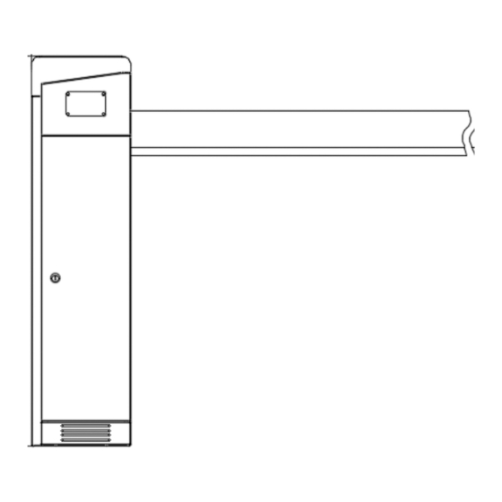
Chapter 1 Overview 1.1 Appearance and Dimensions PB1000 series use the gray painted cabinet. It can be equipped with different types of straight booms. Standard configuration of PB1030 and PB1060 include expansion boom. Length of expansion boom can be up to 800mm. Dimensions are shown in the following figures. -
Page 4: Components Inside The Cabinet
Parking Barrier User Manual Figure 1-1C Dimensions of the PB1060 1.2 Components inside the cabinet Position sensor Gearbox Motor Handle Air switch Four expansion bolts Figure 1-2 Components inside the Chassis... -
Page 5: Working Principles
Parking Barrier User Manual 1.3 Working Principles Power subsystem: Motor and gearbox provide power for the whole system. Speed reduction subsystem: The speed reduction system control the lifting and falling speed of the boom. It makes the boom slow down when the boom stop movement. Spring balance subsystem: A compression spring provides balance for the weight of the boom to keep the boom horizontal. -
Page 6: Chapter 2 Product Installation
Parking Barrier User Manual Chapter 2 Product Installation 2.1 Installation Precautions Install the parking barrier on a level ground. If the ground is not solid and level, a cement base is needed before installation. The boom can be cut, but can’t be increased. After cutting the boom length, the spring balance needs to be set again to achieve new balance. -
Page 7: Boom Installation
Parking Barrier User Manual 4) Install screw pads and use a wrench to tighten nuts, as shown in Figure 2-3D. 5) Close the access door. Figure 2-3A Figure 2-3B Figure 2-3C Figure 2-3D 2.4 Boom Installation Boom Installation Procedure 1) Take out booms. 2) Add glue onto the connection part of the boom, fix the two parts together, as shown in Figure 2-4A. - Page 8 Parking Barrier User Manual Wiping Off Spilled Glue Apply glue Figure 2-4A Applying Glue Figure 2-4B Wiping Off Spilled Glue Adjust the distance 调整距离 Figure 2-4C Installing the Decorative Cap Fasten screws after Decorative cap A adjusting the expansion boom Screw Decorative cap B...
-
Page 9: System Diagram
Parking Barrier User Manual Plastic decorative cap Screw Iron piece Boom Figure 2-4F Installing the Boom to the Chassis 2.5 System Diagram Installation Diagram for the Parking barrier and Wall. The distance between the chassis and the wall should be greater than or equal to 100 mm. The distance between the boom and the wall should be greater than or equal to 100 mm. -
Page 10: Wiring Diagram Of The Push Button Station
Parking Barrier User Manual System Diagram Control room A standard power wire RVV3*1.0 A signal line RVV4*0.5 2.6 Wiring Diagram of the Push Button Station Push Button Station... -
Page 11: Chapter 3 Troubleshoot
Parking Barrier User Manual Chapter 3 Troubleshoot 1) If the boom fails to fall into a level position, adjust position A; if the boom fails to be lifted upright, adjust position B. See Figure 3-2A. 2) If the boom shakes during falling or lifting, adjust position C. The shaking that occurs during lifting is caused by the overlarge spring force. -
Page 12: Chapter 4 Optional Functions
Parking Barrier User Manual Chapter 4 Optional Functions 4.1 Loop Detector Loop detector in the parking system consist of loop, loop detector and control board. The loop is installed under the ground. When loop detect a vehicle, the boom will not fall down, after the vehicle pass, the boom will automatically fall down. -
Page 13: Photo Cell
Parking Barrier User Manual 4.3 Photo Cell When photo cell detect a vehicle, the boom will not fall down, after the vehicle pass, the boom will automatically fall down. The structure of photo cell is shown in the 4-3A and the wiring diagram is shown in the figure 4-3B. -
Page 14: Cooling System
Parking Barrier User Manual 4.4 Cooling System Cooling system consist of 12V power supply, extension board and fan. The installation of fan is shown in the 4-5A and the wiring diagram is shown in the figure 4-5B. Figure 4-5A Figure 4-5B 4.5 Siren Siren requires 12V power supply. - Page 15 Parking Barrier User Manual Figure 4-6...
-
Page 16: Chapter 5 Device Maintenance
Parking Barrier User Manual Chapter 5 Device Maintenance 1) Maintain the boom. Fix the reflective sticker. 2) Tighten terminals connector of the device. 3) Clear dust on components inside the cabinet. Note that technicians should maintain the parking barrier system once a month. -
Page 17: Appendix Wiring Diagram
Parking Barrier User Manual Appendix Wiring Diagram 1) Interface of the Main Control Board Delete All Transmitter Press K4 setting button until D8 yellow light flashes. Hold on K4, press stop button on control board until D9 red light flash one time. The operation successes and will delete all the registered transmitters. Register the transmitter Press K4 setting button until D8 yellow light flashes. - Page 18 Parking Barrier User Manual 3) Wiring Diagram of the Mains Supply and Motor Power supply Air switch Motor 4) Wiring Diagram of the Extension Board and Main Control Board...
Need help?
Do you have a question about the PB1000 Series and is the answer not in the manual?
Questions and answers