Table of Contents
Advertisement
Advertisement
Table of Contents

Related Manuals for ZKTeco PB3000 Series


Summary of Contents for ZKTeco PB3000 Series
- Page 1 User Manual PB3000...
-
Page 2: Table Of Contents
PB3000 User Manual Contents Chapter 1 Overview ............................................1 1.1 Appearance and Dimensions ....................................1 1.2 Components inside the cabinet ................................... 2 1.3 Working Principles.......................................... 3 6M( main boom 3.2m + vice boom 3m .................................. 3 Chapter 2 Product Installation ........................................4 2.1 Installation Precautions ....................................... -
Page 3: Chapter 1 Overview
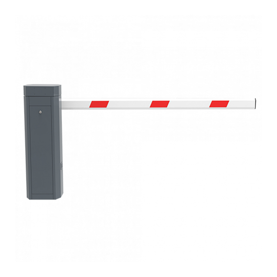
PB3000 User Manual Chapter 1 Overview 1.1 Appearance and Dimensions PB3000 series are equipped with gray painted cabinets. PB3030 and PB3060 include main and vice boom, PB3010 has one main boom. The dimensions are shown in the following figures. Main boom... -
Page 4: Components Inside The Cabinet
PB3000 User Manual Main boom Vice boom: 3000mm Figure 1-3 the boom length of the PB3060 1.2 Components inside the cabinet Position sensor Gearbox Motor Air switch Handle Four expansion bolts Figure 1-4 Components inside the Chassis... -
Page 5: Working Principles
PB3000 User Manual 1.3 Working Principles Power subsystem: The motor and gearbox provide power for the whole system. Speed reduction subsystem: The speed reduction system controls the lifting and falling speed of the boom. It makes the boom slow down when the boom stops movement. Spring balance subsystem: The compression spring provides balance for the weight of the boom to keep the boom horizontal. -
Page 6: Chapter 2 Product Installation
PB3000 User Manual Chapter 2 Product Installation 2.1 Installation Precautions Install the parking barrier on a level ground. If the ground is not solid and level, a cement base is needed before installation. The boom can be cut, but cannot be increased. After cutting the boom length, the spring balance needs to be set again to achieve new balance. -
Page 7: Boom Installation
PB3000 User Manual 5) Close the access door. Figure 2-2 Figure 2-3 Chassis Expansion bolt Screw pad Ground Ground Base concrete Figure 2-4 Figure 2-5 2.4 Boom Installation Boom Installation Procedure 1) Take out booms. 2) Install the booms. (If your purchase is PB3010L/R, there will be only one boom. If your purchase is PB3030L/R or PB 3060L/R there will be a main boom and a vice boom which need to be connected together.) 3) Putting the connection part of vice boom into the main boom, then fixed by 2 screws. - Page 8 PB3000 User Manual Putting the vice boom into the main boom Fasten screws Figure 2-6 Connect the main boom with vice boom together Screw Iron piece Boom Figure 2-7 Installing the Boom to the Chassis...
-
Page 9: System Diagram
PB3000 User Manual 2.5 System Diagram Installation Diagram for the Parking barrier and Wall. The distance between the chassis and the wall should be greater than or equal to 100 mm. The distance between the boom and the wall should be greater than or equal to 100 mm. System Diagram Control room... -
Page 10: Wiring Diagram Of The Push Button Station
PB3000 User Manual 2.6 Wiring Diagram of the Push Button Station Control board... -
Page 11: Chapter 3 Troubleshoot
PB3000 User Manual Chapter 3 Troubleshoot 1) If the boom fails to fall into a level position, adjust position A; if the boom fails to be lifted upright, adjust position B. See Figure 3-1. 2) If the boom shakes during falling or lifting, adjust position C. The shaking that occurs during lifting is caused by the overlarge spring force. -
Page 12: Chapter 4 Optional Functions
PB3000 User Manual Chapter 4 Optional Functions 4.1 Loop Detector Loop detector in the parking system consist of loop, loop detector and control board. The loop is installed under the ground. When loop detect a vehicle, the boom will not fall down, after the vehicle pass, the boom will automatically fall down. -
Page 13: Cooling System
PB3000 User Manual 4.2 Cooling System The cooling system consists of a 12V power supply, an extension board and a fan. The installation of fan is shown in the 4-2 and the wiring diagram is shown in the figure 4-3. Figure 4-2 Figure 4-3... -
Page 14: Chapter 5 Device Maintenance
PB3000 User Manual Chapter 5 Device Maintenance 1) Maintain the boom. Fix the reflective sticker. 2) Tighten terminals connector of the device. 3) Clear dust on components inside the cabinet. Note that technicians should maintain the parking barrier system once a month. -
Page 15: Appendix Wiring Diagram
PB3000 User Manual Appendix Wiring Diagram 1) Interface of the Main Control Board Delete All Transmitter Press K4 setting button until D8 yellow light flashes. Hold on K4, press stop button on control board until D9 red light flashes one time. All the registered transmitters will be deleted after successful operation. Register the transmitter Press K4 setting button until D8 yellow light flashes. - Page 16 PB3000 User Manual 3) Wiring Diagram of the Mains Supply and Motor 4) Wiring Diagram of the Extension Board and Main Control Board...
Need help?
Do you have a question about the PB3000 Series and is the answer not in the manual?
Questions and answers