
Related Manuals for NSK MEGATORQUE MOTOR SYSTEM


Summary of Contents for NSK MEGATORQUE MOTOR SYSTEM
- Page 1 ® MEGATORQUE MOTOR SYSTEM User’s Manual (EDC Driver Unit CC-Link Option) M-E099DC0C2-157 Document Number: C20157-02...
-
Page 2: Limited Warranty
Ltd. is notified of in writing within, which comes first, one (1) year of shipment or 2400 total operation hours. NSK Ltd., at its option, and with transportation charges prepaid by the claimant, will repair or replace any product which has been proved to the satisfaction of NSK Ltd. to have a defect in material and/or workmanship. -
Page 3: Table Of Contents
Contents 1. Introduction -----------------------------------1-1 4. Alarm and Warning --------------------------4-1 1.1.Notes for Users -------------------------------------------1-2 4.1. Cause and Rmedy of Alarm and Remedy -------- 4-1 1.1.1. Notes for Safety ------------------------------------1-2 4.1.1. C4: Fieldbus Error -------------------------------- 4-1 4.1.2. C5: Fieldbus Warning -------------------------- 4-2 2. - Page 4 (Blank Page) — ii —...
-
Page 5: Introduction
1. Introduction 1. Introduction This manual describes an option of the Megatorque Motor System that consists of the EDC Driver Unit CC-Link option. Please refer to the user’s manual of the Megatorque Motor System (EDC Driver Unit System) for other details. - Page 6 1. Introduction (Blank Page) — 1-2 —...
-
Page 7: Specifications Of Hardware Interface
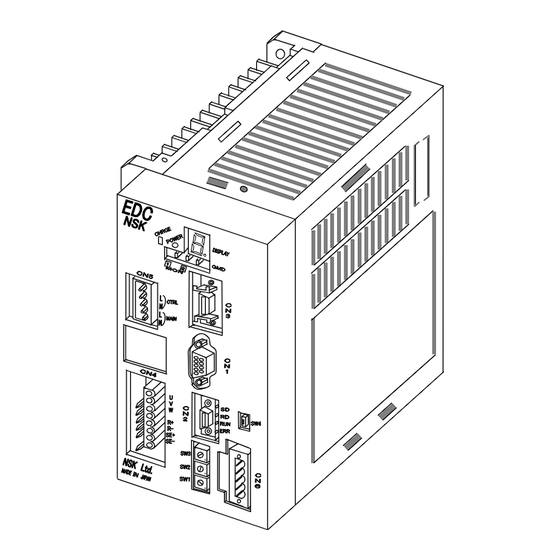
2. Specification 2. Specifications 2.1. General Specifications Table 2-1: General specifications Item Description CC–Link Ver.1.10 Protocol Number of slave stations 2 Remote device stations (Type of station) 16 ports are available for any function Number of addressable assignment remote input ports 7 ports are available for any function Number of addressable assignment... - Page 8 2. Specification Fig. 2-2: EDC Driver Unit compatible with CC-Link Network (Motor type: PS3060 and PS3090) — 2-2 —...
-
Page 9: Cn2: Control Input/Output Signal Connector
2. Specification 2.2.2. CN2: Control Input/Output Signal Connector The table below shows the connectors for CN2. Table 2-2: Connector list Connector of Driver Unit DDK Ltd. DHF-RAA10-233NB-FA or equivalent Mating connector DDK Ltd DHF-PDA10-3-A01-FA or equivalent ◊ An optional cable set (M-E011DCCN1-001) with the mating connector to the CN2 I/O connector of the Driver Unit is available (Sold separately). -
Page 10: Cn2 Pin-Out
2. Specification 2.2.2.1. CN2 Pin-Out Figure 2-3 below shows the shipping set of the pin-out arrangement of the CN2 connector. You may change the function assignment of each signal port. (Except some ports that are dedicated to a certain function) ◊... -
Page 11: Cn2 Signal List
2. Specification 2.2.2.2. CN2 Signal List Table 2-3: Signal name and function (shipping set) Port Signal Contact Signal function Function code code logic 24 VDC external power DC24 External power supply for input signal supply Do not connect Interrupts the positioning and stops with the dynamic Normaly Emergency stop EMST... -
Page 12: Cn6: Interface Connector
2. Specification 2.2.3. CN6: Interface Connector The CN6 connector interfaces with the CC-Link network. The followings are the reference for the connectors that are used for the CN6 connector. Table 2-4: CN6 mating connectors MSTB2,5/5-GF-5,08AU or Phoenix Contact Gmbh, & Co. Connector, Driver Unit side equivalent MSTB2,5/5-STF-5,08AU or... -
Page 13: Sw1•Sw2: Station Number Switch
2. Specification 2.2.4. SW1•SW2: Station Number Switch These rotary switches set the station number from 1 to 64. The SW1sets the tens place of the number, while the SW2 switch sets the ones place. Table 2-7: Station number switch Station number D river U nit ’s upp er side (Never set) 1 (Shipping set) -
Page 14: Led Status Monitor (Sd, Rd, Run And Err)
2. Specification 2.2.7. LED Status Monitor (SD, RD, RUN and ERR) The monitor indicates the status of conection and communicatoin with the network. When the communication status is nomal, the indicators RUN, RD and SD are on, and that of ERR is off (In some baud rate, the RD and SD indicators seem like blinking). -
Page 15: Wiring Example
2. Specification 2.2.8. Wiring Example Refer to “Figure 2-4: Wiring example” below for wiring the Drive Unit to the CC-Link. ◊ Be sure to use a cable dedicated to the CC-Link. ◊ The wiring order is not necessarily the same order of station numbers. Fig. -
Page 16: Software Interface Specification
2. Specification 2.3. Software Interface Specification 2.3.1. Remote Input/Output Table 2-12 “Remote Input/Output” on the next page shows the function of Input/Output of the CN6 interface connector (Shipping set). Excluding some ports, you may change the function assignment to the remote Input/Outpu ports. Please refer to “3.5 Function Assignment of Control Input/Output”... - Page 17 2. Specification Table 2-12: Remote Input/Output (m: A register number derived from the top station number) Port Signal Port Signal Output Function Input Function code code code code Interrupts the positioning Reports that the Motor is RXm0 DRDY RYm0 EMST and stops with the dynamic ready for the operation brake...
-
Page 18: Remote Register
2. Specification 2.3.2. Remote Register Table 2-13 “Remoto Register” shows the functon of remote register of the CN6 : interface connector. Remote register outputs data monitoring, such as a coordinate data, using two words of remote register RWr. ◊ The data consists of 32 bit integer with the sign. Table 2-13: Remote Register m: A register number derived from the top station number Output... - Page 19 ◊ The current velocity is given in the units of a thusandth as –5.000 when the Motor is rotating to the minus direction at the velocity of 5 [S Fig. 2-5: Description of “Monitor TV” (Megatorque Motor System User’s Manual [EDC Driver Unit System]) The decimal point is abbreviated when outputting to the CC-Link.
- Page 20 2. Specification (Blank Page) — 2-14 —...
-
Page 21: Operation
3. Operation 3. Operation 3.1. Operation Mode and Input/Output There are two ways to input signals to the Driver Unit CN2: control Input/Output connector and remote input by the CN6: interface connector. There are two operation modes to receive those inputs exclusively. -
Page 22: Change Of Operation Mode
◊ When the system detects any abnormality related to the CC-Link, it starts up with the maintenance mode. The command CP (Control mode priority) changes the operation mode. Fig. 3-1: Switching the operation mode NSK MEGATORQUE SDC1A80_0009.0 SXSYS1006.2,XOP1 Fieldbus mode right after the power is turned on... - Page 23 3. Operation 1) Input the command MO (Motor off) to deactivate the Motor servo. 2) Set the parameter CP (Control priority) to the CP0 (Maintenace mode). #CP0 3) Specify the port number to which the Input SVON (Servo on) is assigned by the command PI (Edit input port) to readout the parameter FN (Port function).
-
Page 24: Monitoring Control Input/Output
3. Operation 3.4. Monitoring Control Input/Output The Monitor IO (Input/Output monitor) monitors the state of remote inputs and outputs of the CN6 interface connector. Figure 3-2 “Monitor of the control Input/Output functions and their state” below shows the relation between the function of control inputs and outputs of the Driver Unit and the Monitor IO. You can monitor the state of each part using Monitor IO0 to IO4 accordingly. -
Page 25: Monitoring The State Of Remote Inputs/Outputs: Monitor Io4
3. Operation 3.4.1. Monitoring the State of Remote Inputs/Outputs: Monitor IO4 The monitor reports the current state of remote Inputs and Outputs of the CN6 Interface connector. ◊ Input as “IO4/RP”. Input the BS key to stop real-time readout. Fig. 3-3: Readout Example of Monitor IO4 Guide GFEDCBA9876543210 00000000000000000... -
Page 26: Monitor
3. Operation 3.4.2. Monitoring State of the CC-Link Interface: Monitor BS Monitor BS reports the current state of the CC-Link Interface. ◊ Input as “BS/RP”. Input the BS key to stop real-time readout. Fig. 3-4: Readout example of Monitor BS #BS/RP Guide FEDCBA9876543210... -
Page 27: Function Assignment Of Control Inputs/Outputs
3. Operation 3.5. Function Assignment to Control Inputs/Outputs You may change the function assignment to the ports of CN6 (Interface connector) and CN2 (Control I/O connector). (Excludes certain port.) ◊ Counter change to an expanded function ◊ Transfer a previously assigned function to other port. ◊... -
Page 28: Function Of Conrol Inputs
3. Operation 3.5.1. Function of Conrol Inputs You may assign a function to each control input port. This feature, for example, permits you to change a function preset to an input port to other function, or to switch to one of expanded functions. - Page 29 3. Operation Table 3-5: Extended input function Port Signal Input Signal name Function Logic in the CN6 code code Holds an operation and program 0: Normal ‒ ‒ Hold execution 1 : Hold Changes the operation velocity 0 : Normal ‒...
-
Page 30: Function Of Control Outputs
3. Operation 3.5.2. Function of Control Outputs You can set the function of control outputs and the In-position stability timer. You may change the preset input port function to other function , or to switch to one of expanded functions. ◊... - Page 31 3. Operation Table 3-7: Function of extended output Port Signal Output Signal name Function Logic in the CN6 code code 0: Not in the proximity Reports that the Motor is ‒ ‒ NEARB Target proximity B 1: The Motor is nearing to the approaching to the destination target position ‒...
-
Page 32: Editing Coptrol Inputs/Outputs
3. Operation 3.5.3. Editing Coptrol Inputs/Outputs 3.5.3.1. Editing Control Inputs The command PI (Edit input port) edits the function setting to the control input ports. When the editing mode of control input is established by the command PI, the setting of the parameters FN (Port function) and NW (Anti-chattering timer) become effective. - Page 33 3. Operation Setting function by direct input Refer to the following, for an example, how to change the function of the input port PI14 to the “Input HLD (Hold)” from the “Input PRG7 (Internal program channel selection 7)”. 1) Turn the Motor servo off by the command MO (Motor off). 2) An inputof the port number by the command PI (Port number: PI14) reads out the parameter (“PRG7”...
- Page 34 3. Operation Selection and setting of function Select and set the control input function by “ “ option. The procedure shown on “Fig. 3-5: Seletion and setting of control input” changes the function of input port PI14 to the “Input HLD (Hold)” from the “Input PRG7 (Internal program chanel selection 7)”. Fig.
-
Page 35: Editing Control Outputs
3. Operation 3.5.3.2. Editing Control Output The command PO (Edit output port) edits the function setting to the control output ports. When the editing mode of control output is established by the command PO, the setting of the parameters FN (Port function) and ST (Anti-chattering timer) become effective. ◊... - Page 36 3. Operation Function setting by direct input Refer to the following, for an example, how to change the function of the output port PO7 to “Output ZONEA (Zone A)” from “Output NEARA (Near position A)”. 1) Specify the output port number by the command PO to read out the setting of parameter FN. (The function of “NEARA”...
- Page 37 3. Operation Selection and setting of output function Select and set the control input function by “ “ (option). The procedure shown on “Fig. 3-6: Selection and setting of output function” change the function of the port PI14 to “Output ZONE A (Zone A)” from “Output NEARA (Near position A)”. Fig.
-
Page 38: Masking The Function Of Control Inputs/Outputs
3. Operation 3.5.3.3. Masking the Function of Control Inputs/Outputs Refer to the following , for an example, how to change the function of input port P16 from “Input STP (Stop)” to “NONE (No function: Masked)”. 1) Input the command “MO (Motor off)” to put the Motor in the state of “Servo off”. 2) Specify an input port number by the command PI (Edit control input) to read out the parameter FN (Input function) . -
Page 39: Forcible Change In Setting Control Output Port Function
1) According to “Table 3-6: Remote output ports and assigned function,” the port name of the remote output RXm0 is PO0. /NSK ON 2) Input the password as “ ”. - Page 40 3. Operation (Blank Page) — 3-20 —...
- Page 41 4. Alarm and Warning 4. Alarm and Warning 4.1. Cause and Remedy of Alarm and Warning 4.1.1. C4: Fieldbus Error The Driver Unit gives the alarm if an error in the built-in CC-Link interface unit occurred and disabled continuous communication. ◊...
- Page 42 4. Alarm and Warning 4.1.2. C5: Fieldbus Warning This warning reports an error in the fieldbus that is recoverable. ◊ The warning reports the error in setting of station number or the baud rate, and the line breakage of the fieldbus board. Table 4-3: Status when the fieldbus warning OTPA 7 seg...
- Page 43 ® MEGATORQUE MOTOR SYSTEM User’s Manual (EDC Driver Unit CC-Link Option) Document Number: C20157-02 Apr 28, 2006 1st Edition 1st Printing Nov 15, 2011 2nd Edition 1st Printing NSK Ltd.
Need help?
Do you have a question about the MEGATORQUE MOTOR SYSTEM and is the answer not in the manual?
Questions and answers