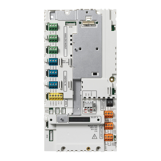
Summary of Contents for ABB +P906
- Page 1 ABB low voltage drives Supplement External control unit (+P906) for ACH580-04, ACQ580-04 and ACS580-04 drives...
-
Page 2: List Of Related Manuals
Internet on the inside of the back cover. For manuals not available in the Document library, contact your local ABB representative. The code below opens an online listing of the manuals applicable to the product: ACH580-04 manuals... - Page 3 External control unit (+P906) for ACH580-04, ACQ580-04 and ACS580-04 drives Table of contents 1. Safety 3. Installation 2017 ABB Oy. All Rights Reserved. 3AXD50000167555 Rev A EFFECTIVE: 2017-09-30...
-
Page 5: Table Of Contents
Providing feedback on ABB manuals ........ -
Page 7: Introduction To The Supplement
Introduction to the supplement 7 Introduction to the supplement Safety WARNING! Only qualified electricians are allowed to carry out the work described in this supplement. Read and obey the safety instructions in the product’s hardware manual. If you ignore them, injury or death, or damage to the equipment can occur. - Page 8 ABB and its affiliates are not liable for damages and/or losses related to such security breaches, any...
-
Page 9: Hardware Description
Hardware description 9 Hardware description Overview Option +P906 allows the drive control unit to be installed separately from the main drive module, for instance in a separate compartment. The external control unit option makes the drive module removal easier, as the customer control cabling can stay in place while the module is removed. - Page 10 10 Hardware description The connections at the module end are located behind one of the front covers. Details of the connections between the control unit and the module are shown below. Control unit Drive module ZBIB BPOW X3:1 X3:1 X3:2 X3:2 ZBIB BGDR...
-
Page 11: Installation
Installation 11 Installation Contents of this chapter This chapter describes the unpacking and installation of the external control unit. -
Page 12: Unpacking The Delivery And Preparing The Module For Installation
12 Installation Unpacking the delivery and preparing the module for installation The drive module delivery includes several boxes. The cartons on top of the main module box contain selected options (shrouds, etc., if ordered). The external control unit is in a separate box inside the main module box. - Page 13 Installation 13 transit. It is recommended that these are removed from the module before installation. • b) Use a T20 torx driver to remove the two screws that attach the front cover of the drive module. • c) Pull the cover towards you until it is away from the locating pins, and place the cover to one side, to find the control connections at the drive module end.
- Page 14 14 Installation • d) Check the connection labelling for future reference. BPOW BGDR • e) Disconnect the cables from the control connections and then carefully remove them from the drive module via the rubber grommet. Wind the cables carefully into the plastic bag supplied, ready for installation later.
-
Page 15: Installing The External Control Unit
Installation 15 Installing the external control unit 1. Determine where the control unit is to be located. Take into account the cable lengths (see Hardware description on page 9) and the physical dimensions of the control unit assembly (see Dimension drawings on page 21). - Page 16 16 Installation • e) Connect the cables to their connections on the ZBIB board (the ground connection is shown below in step 4). • f) Wind the remaining cables into the plastic bag again. 4. The kit includes a plate for the customer cable screens. Attach the small bracket and the ground connection first, then the full clamp plate.
- Page 17 Installation 17 • b) Connect the ground connection.
- Page 18 18 Installation...
-
Page 19: Maintenance
Maintenance 19 Maintenance Removing the drive module The drive hardware manual describes the removal/replacement of the drive module in full. With the external control unit option +P906, the module removal procedure differs slightly: before you detach the drive module, you must disconnect the control unit cables from the drive module in the following way: 1. - Page 20 20 Maintenance 2. Disconnect the optical, 2 × STO, 24 V, and ground connections from the drive module, and carefully remove the cables from the drive. 3. Wind the cables so they will not be damaged as the drive module is removed. 4.
-
Page 21: Dimension Drawings
Dimension drawings 21 Dimension drawings Note: The control unit is equipped with two option modules. - Page 22 22 Dimension drawings 3AXD50000137176 Rev B Note: There are two side views in the drawing: the side view on the left (1) shows the control unit dimensions without option modules, the side view on the right (2) shows the dimensions with option modules.
-
Page 23: Further Information
Product and service inquiries Address any inquiries about the product to your local ABB representative, quoting the type designation and serial number of the unit in question. A listing of ABB sales, support and service contacts can be found by navigating to www.abb.com/searchchannels. - Page 24 Contact us www.abb.com/drives www.abb.com/drivespartners 3AXD50000167555 Rev A (EN) 2017-09-30...


Need help?
Do you have a question about the +P906 and is the answer not in the manual?
Questions and answers