Zehnder Rittling ComfoAir E350 Manual For The Installer
Hide thumbs
Also See for ComfoAir E350:
- Quick manual (4 pages) ,
- Manual (40 pages) ,
- Manual for the user (16 pages)
Table of Contents
Advertisement
Quick Links
Advertisement
Table of Contents

Related Manuals for Zehnder Rittling ComfoAir E350


Summary of Contents for Zehnder Rittling ComfoAir E350
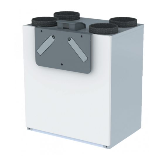
- Page 1 ComfoAir E350 Manual for the installer Heating Cooling Ventilation Filtering...
-
Page 2: Foreword
Foreword Information given in the Instructions for the user. Please read this manual carefully before operating General information about the ventilation system. the unit. Warranty and liability conditions EC declaration of conformity. With the help of this manual, you can install, commission Replacing filters in the unit. -
Page 3: Table Of Contents
Contents Foreword .....................................2 Safety instructions ..................................4 Installation conditions ..................................4 Transport and unpacking ................................5 Technical specifications.................................6 4.1 Configuration of the unit ................................7 4.2 Connection diagram ................................8 4.3 Dimension sketch ................................10 Installation procedures ................................11 5.1 Wall mounting ..................................11 5.2 Floor mounting ...................................12 5.3 Installation of the condensation drain ...........................12 5.4 Installation of the air ducts ..............................13 Commissioning procedures ................................14... -
Page 4: Safety Instructions
1 Safety instructions 2 Installation conditions ■ Always comply with the safety regulations ■ Connect the unit to a 230 V~ 50 Hz power supply. Any other mains connection will damage the unit; in this document. Failure to comply with the ■... -
Page 5: Transport And Unpacking
3 Transport and unpacking The permissible storage and transport temperature is -20°C to +50°C. Treat the unit with care during transport and unpacking. Make sure the packing material is disposed of in an environmentally friendly manner. Checking the delivery Contact your supplier immediately in case of damage or an incomplete delivery. -
Page 6: Technical Specifications
4 Technical specifications ComfoAir E350 Performance Minimum airflow if preheater on 100 m Minimum airflow if preheater off 50 m Maximum airflow 350 m Heat efficiency level Electrical connection details Maximum performance/power without preheater 120 W 1.03 A Maximum performance/power with preheater 1580 W 7.38 A... -
Page 7: Configuration Of The Unit
4.1 Configuration of the unit Identification Part Identification plate with all important details of the unit (not illustrated). Inscription with the air connections on the protective cover of the display. Power cable with 230 V plug (not illustrated). 2 adjustment caps. Input for connecting a bathroom switch. -
Page 8: Connection Diagram
4.2 Connection diagram Key: Meaning Code Meaning Code Right-hand unit Left-hand unit Green / Yellow BYPASS MOTOR 11 extract air BYPASS MOTOR 20 outdoor air N / BU Blue BYPASS MOTOR 20 outdoor air BYPASS MOTOR 11 extract air L / BK Brown or black FAN 22 supply air FAN 12 exhaust air... - Page 9 Front view of main PCB EN - 9...
-
Page 10: Dimension Sketch
4.3 Maatschets 4.3 Maatschets 4.3 Dimension sketch Maßskizzen 4.3 Maatschets CA300 CA400 CA300 CA400 Top view Above view CA300 CA400 Front view Frontal view Side view Bottom view Below view 10 - NL 10 - NL 10 - NL 10 - EN... -
Page 11: Installation Procedures
5 Installation procedures ■ Make sure interfering and sensitive cables cross each other in perpendicular. During installation, take account of electromagnetic ■ Ensure that the cables used for the controls meet interference. the requirements specified in the section “Technical ■ Ensure that there is a barrier (e.g. separate duct specifications”. -
Page 12: Floor Mounting
5.2 Floor mounting Example of instruction 1100 Use a Zehnder mounting frame on the floor Install the mounting frame according to the Place the unit on the mounting frame. (available as an optional extra) for walls instructions in the corresponding manual. ■... -
Page 13: Installation Of The Air Ducts
5.4 Installation of the air ducts ■ Zehnder recommends that you fit thermal and moisture resistant insulation to the supply duct from Air duct system the unit up to the supply valves. This will prevent unnecessary temperature loss in the summer and winter;... -
Page 14: Commissioning Procedures
6 Commissioning procedures Explanation 6.1 Overview of the display Current airflow: ■ No icon = No ventilation The unit has a touchscreen display for readout and = LOW SETTING; ■ programming the unit. = MEDIUM SETTING; ■ Main screen of display = HIGH SETTING;... -
Page 15: Service Menu
6.2 Service menu The service menu is protected by a password (4210) that remains active for at least 15 minutes. Each number The service menu lists all the steps required for of the password must be entered individually with the commissioning the unit and tracing the causes of any arrow keys and confirmed with the confirmation key. -
Page 16: Programming Air Specifications
6.3 Programming air specifications Close all windows and doors. Connect the device to the mains. Go to the settings for the installer. Select a language and confirm that the siphon is Open all valves connected to the ventilation (MENU > Login; Login code= 4210 mounted correctly. -
Page 17: Rf Controls
6.4 RF controls To enable the use of RF controls, the unit needs to be equipped with an RF PCB. The RF PCB has to be ordered separately and can be installed later on. If RF ACTIVATION is set to ON: Set the Set the RF ACTIVATION on the display of Set METHOD on the display of the unit to RF ACTIVATION on the display of the... -
Page 18: Explanation Of Ventilation Settings Menu
6.5 Explanation of VENTILATION SETTINGS 6.8 Explanation of TEMPERATURE menu menu The unit is equipped with 5 temperature sensors. The readout of the current value of these sensors appears in The building regulations describe how much fresh the TEMPERATURE menu in the sequence given below. supply air must be provided to each room. -
Page 19: Explanation Of Unit Specification Menu
6.10 Explanation of UNIT SPECIFICATION menu 6.12 Explanation of ANALOGUE 0-10 V menu In the UNIT SPECIFICATION menu, the readout of the (standard) and RF SETTING (optional) basic unit details appears in the sequence below. The unit can be controlled with any analogue 0-10 V Meaning signal and/or an RF signal. -
Page 20: Explanation Of The System Test Menu
6.15 Explanation of RESTORE TO FACTORY 6.14 Explanation of the SYSTEM TEST menu SETTINGS menu A system test can be initiated in the SYSTEM TEST The factory settings of the unit are permanently saved menu. to the control PCB. Using the RESTORE TO FACTORY (MENU>Login>SYSTEM TEST) SETTINGS menu, the unit can be switched back to the factory settings. -
Page 21: Available Accessories
What is the METHOD CONTROL? 7 Available accessories With this method, an incoming signal generates a (Example) Comment standard outgoing signal. Appearance & Name Use a Zehnder mounting frame on the floor. This will reduce contact noise as What is POSITIVE? much as possible. -
Page 22: Available Controls
8 Available controls Picture and name Comment Connect a switch / push-button as per the connection diagram in the section ‘Connection diagram’. Sample Sample Any switch / push-button can be used (this switch is not available from Zehnder). Bathroom / Pulse switch Wired control for manual control of the unit. -
Page 23: Quick Installation Guide
9 Quick installation guide Key: Code Meaning Supply and extract air on the right-hand side Supply and extract air on the left-hand side Outdoor air Supply air Extract air Exhaust air Wall mounting Installation of the controls 12 V 640mm DISPLAY 0-10 V ≥1080mm... - Page 24 Zehnder Group Sales International • Zehnder Group Deutschland GmbH Almweg 34 · 77933 Lahr · Germany T +49 78 21 586-392 •· F +49 78 21 586-406 sales.international@zehndergroup.com • www.international.zehnder-systems.com...
Need help?
Do you have a question about the ComfoAir E350 and is the answer not in the manual?
Questions and answers