Table of Contents
Advertisement
Quick Links
Advertisement
Table of Contents

Related Manuals for Zehnder Rittling ComfoAir 350 Basic Series


Summary of Contents for Zehnder Rittling ComfoAir 350 Basic Series
- Page 1 ComfoAir 350 Basic Installer manual Heating Cooling Fresh Air Clean Air...
- Page 2 All rights reserved. This manual has been compiled with the utmost care. The publisher cannot be held liable for any damage caused as a result of missing or incorrect information in this manual. In case of dis putes the Dutch version of these instructions will be binding. EN - II...
-
Page 3: Table Of Contents
Table of Contents Preface ................................1 INTroduCTIoN ............................. 1 Warranty and liability .......................... 1 1.1.1 Guarantee conditions ........................ 1 1.1.2 Liability ............................1 Safety ..............................2 1.2.1 Safety regulations ........................2 1.2.2 Safety provisions and measures ....................2 1.2.3 Pictograms used ........................2 For ThE FITTEr ............................ - Page 4 EN - IV...
-
Page 5: Preface
Preface Warranty and liability Carefully read this manual before use. 1.1.1 Guarantee conditions The ComfoAir is covered by a manufacturer’s war- This manual provides all the information required for ranty for a period of 24 months after fitting up to a safe and optimal installation and maintenance of the ComfoAir 350 Basic. -
Page 6: Safety
Safety 1.2.2 Safety provisions and measures ■ The ComfoAir cannot be opened without using 1.2.1 Safety regulations tools; ■ It should not be possible to touch the fans, there- Always comply with safety regulations in this manual. fore ducting must be connected to the ComfoAir Non-compliance with the safety regulations, warn- at a minimum duct length of 900mm. -
Page 7: For The Fitter
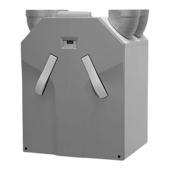
For the Fitter ComfoAir configuration The standard ComfoAir configuration consists of: ■ External casing (A) of coated sheeting; ■ Interior (B) of high-quality, expanded polypropylene EPP; ■ 4 connections (C) for the air ducts; ■ 2 plate filters (D) for air purification. Filter classification: outside air G4, return air G4; ■... -
Page 8: Technical Specifications
Technical specifications ComfoAir 350 nL (normal air volumes) Position Ventilation capacity Power Low Setting 100 m /h at 20 Pa 21 W Medium Setting 150 m /h at 65 Pa 44 W High Setting 225 m /h at 150 Pa 105 W Maximum 325 m... - Page 9 ComfoAir 350 hL (high air volumes) Position Ventilation capacity Power Low Setting 125 m /h at 25 Pa 27 W Medium Setting 225 m /h at 150 Pa 105 W High Setting 300 m /h at 230 Pa 196 W Maximum 325 m /h at 235 Pa...
-
Page 10: Dimension Sketch
dimension sketch ø160 ø151 CONDENSATION DRAIN CONDENSATION DRAIN RIGHT-HAND VERSION LEFT-HAND VERSION CONDENSATION DRAIN ø32 (OUTSIDE) EN - 6... -
Page 11: Installation Conditions
Installation conditions The ComfoAir is supplied in the following types: In order to determine whether the ComfoAir can be Type installed in a certain area, the following aspects must ComfoAir 350 L Basic be taken into account: ■ The ComfoAir must be installed according to the ComfoAir 350 R Basic general and locally applicable safety and installa- Meaning of the suffixes:... -
Page 12: Connection Of The Air Ducts
2.6.2 Connection of the air ducts 2.6.3 Connection of the condensation drain The following aspects must be taken into account, while installing the air ducts: ■ Install the air exhaust duct so it drains in the di- rection of the ComfoAir. ■... -
Page 13: Commissioning The Comfoair
Commissioning the ComfoAir Shown in display After installation, the ComfoAir must be commis- Ventilation setting absent sioned. Ventilation setting low Ventilation setting medium This can be done via the P menus on the digital op- erating device. These P menus can be used to enter Ventilation setting high various settings (ventilation programmes, in particu- Menu symbol... -
Page 14: P Menus For The Installer
2.7.2 P menus for the installer Menus with a line at minimum and maximum value are Reading menus. Menu P3 ¨ Setting ventilation programmes Ventilation programme values Submenu description Minimum Maximum General reset 0% or 15% nL / HL 15% / 15% Setting the capacity (in %) of the nL / HL exhaust fan in... - Page 15 Menu P5 ¨ Setting additional programmes Additional programme values Submenu description Minimum Maximum General reset Activation of the open fire programme. 0 (= No) 1 (= Yes) 0 (= No) 1 (= Yes) Always keep this setting on Default. Confirming the presence of a bypass. 0 (= No) 1 (= Yes) The standard ComfoAir configuration includes a bypass.
- Page 16 Menu P7 ¨ Reading malfunctions (and system information) (Malfunction) information values Submenu description Minimum Maximum General reset Current software version. Version number of the software (without “v”) Most recent malfunction. Code in accordance with alarm and malfunction alert Malfunction before the most recent one Code in accordance with alarm and malfunction alert Malfunction before the most recent two Code in accordance with alarm and malfunction alert...
-
Page 17: Programming Air Specifications
Programming air specifications After installation, the ComfoAir must be programmed. This can be done using the air specifications of the 5. Check if both fans function in the three speed set- ComfoAir above. tings. 6. Switch the ComfoAir to high speed. The default settings of the ComfoAir nL are: 7. -
Page 18: Maintenance By The Installer
Maintenance by the installer When reassembling the front cover, the The following maintenance must be carried out by the lower section must first be inserted behind installer: the raised edge to ensure a good seal. ■ Inspecting and (if necessary) cleaning the heat exchanger;... -
Page 19: Inspecting And Cleaning The Fans
When reassembling the leakage tray the 2.9.2 Inspecting and cleaning the fans openings in the leakage tray must be on the side of the condensation drain. Check the fans once every 2 years. 11. Inspect and if necessary clean the heat exchang- 1. -
Page 20: Malfunctions
2.10 Malfunctions 2.10.2 3-position switch with malfunction indicator Malfunctions in the ComfoAir are reported as follows: ■ The malfunction alert appears on the display; The 3-position switches that are fitted with a malfunc- ■ The malfunction indicator on the 3-position tion indicator show when a malfunction or filter dirty switch lights up. -
Page 21: What To Do In The Event Of A Malfunction / Troubleshooting
2.10.3 What to do in the event of a malfunction / Troubleshooting Below are a number of troubleshooting tips for the malfunction alerts described previously which can appear on the digital operating device in the event of a malfunction. A1 / A2 / A3 / A4 NTC sensor T1 / T2 / T3 / T4... - Page 22 Malfunction in the bypass Remove the handles from the ComfoAir. Remove the filters from the ComfoAir. Release the front panel by unscrewing the screws. Slide the front panel upwards and remove the front panel from the ComfoAir. Release the cover panel by unscrewing the screws Remove the cover...
- Page 23 Reconnect the the ComfoAir. the ComfoAir. power to power to the ComfoAir. the ComfoAir. Replace the Replace the Replace the Replace the control circuit control circuit NTC sensor. NTC sensor. board board Malfunction Malfunction Malfunction Malfunction Set P51 on "0" and Set P51 on "0"...
- Page 24 Reconnect the power to the ComfoAir. ,Fil' ,tEr' Internal Filter is dirty Malfunction Set P59 at "0". Press “OK” on the display for at least 4 seconds until the filter Reset the malfunction warning disappears. (P74 on 1) Disconnect the power from the ComfoAir.
-
Page 25: Malfunctions (Or Problems) Without Alerts
2.10.4 Malfunctions (or problems) without alerts An overview of the malfunctions (or problems) without notifications is given below. Problem/Malfunction Indication Check / action Check the fuse on the control circuit System switched off Power supply on board ■ If the fuse is defective, replace fuse ■... -
Page 26: Service Parts
2.11 Service parts The following table contains an overview of the spare parts available for the ComfoAir. Number Part Article number Fans (left and right) 400200010 ComfoAir 350 control circuit board 400300010 Temperature sensor T2 / T4 (fans) 400300040 Temperature sensor T1 / T3 (bypass) 400300030 Servo motor &... -
Page 27: Wiring Diagram: Comfoair 350 Basic - Left-Hand Version
2.12 Wiring diagram: ComfoAir 350 Basic – LEFT-hANd version SA 1-3V (N) Blue (L3) Brown SA 1-3V (N) Blue (N) Blue SAI 1-3V (L3) Brown (L3) Brown 23 - EN (N) Blue... -
Page 28: Wiring Diagram: Comfoair 350 Basic - Right-Hand Version
2.13 Wiring diagram: ComfoAir 350 Basic – rIGhT-hANd version CASING Blue Brown Brown Blue VENT. VENT. Preheater malfunction indicator of wired 3-position switch DISPLAY White ( Blue(-) Yellow (0-10V) Yellow (0-10V) Blue (-) White ( Brown Brown White White Brown Brown White White... -
Page 29: Eec Declaration Of Conformity
2.14 EEC declaration of conformity Zehnder Group Nederland B.V. Lingenstraat 2 8028 PM Zwolle-NL Tel.: +31 (0)38-4296911 Fax: +31 (0)38-4225694 Company register Zwolle 05022293 EEC declaration of conformity Machine description : heat recovery units: ComfoAir 350 series Complies with the following directives : Machinery Directive (2006/42/EEC) Low Voltage Directive (2006/95/EEC) - Page 30 EN - 26...
- Page 31 27 - EN...
- Page 32 Zehnder Comfosystems • A division of Zehnder Group UK Ltd Unit 1, Brookside Avenue • Rustington West Sussex • BN16 3LF T +44 1903 777 333 • F +44 1903 782 398 comfosystems@zehnder.co.uk • www.zehnder.co.uk/comfosystems...
Need help?
Do you have a question about the ComfoAir 350 Basic Series and is the answer not in the manual?
Questions and answers